1
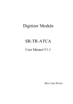
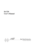
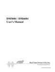
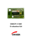
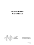
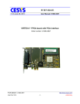
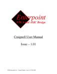
ATCA-MIMO-ISOL ATCA-MIMO-ISOL User Manual V1.0 Thursday, 19 February 2015 ATCA-MIMO-ISOL User Manual ATCA-MIMO-ISOL ........................................................................................................ 1 User Manual .................................................................................................................... 1 ATCA-MIMO-ISOL Technical Specifications ............................................................... 3 2 3 1.1 Introduction................................................................................................................ 3 1.2 Specifications .............................................................................................................. 4 ATCA-MIMO-ISOL Description ............................................................................ 6 2.1 Board Architecture .................................................................................................... 6 2.2 Analogue inputs.......................................................................................................... 8 2.3 Analogue outputs ....................................................................................................... 9 2.4 EIA-485 digital IO ................................................................................................... 10 2.5 RS-232 Interface ...................................................................................................... 11 FPGA Description ................................................................................................. 12 3.1 FPGA Architecture .................................................................................................. 12 3.2 Registers offsets ........................................................................................................ 13 3.3 Register Description ................................................................................................ 14 3.3.1 STATUS + REVISION ID register __________________________________________ 14 3.3.2 COMMAND register _____________________________________________________ 14 3.3.3 DMA BUFFER NUMBER + DMA BYTE SIZE register _________________________ 14 3.3.4 DMA CURRENT BUFFER register _________________________________________ 15 3.3.5 DMA0 to DMA15 ADDRESS registers ______________________________________ 15 3.3.6 DAC1 to DAC8 registers __________________________________________________ 15 4 Special Handling and Operation Considerations................................................. 16 5 Acronyms ............................................................................................................... 17 6 Revision History ..................................................................................................... 18 2 ATCA-MIMO-ISOL User Manual ATCA-MIMO-ISOL Technical Specifications 1.1 Introduction This ATCA single width card comprises a main board, a carrier board, isolated ADC modules and a rear transition module (RTM) mechanically connected together. Up to 12 cards can be inserted on an ATCA shelf and interconnected in a full-mesh topology with sub-microsecond data transport latencies. This card is especially suitable for MIMO controllers since: The data sampled by all ADCs of all cards is available simultaneously on all FPGA processors (one per board); Processed data in each FPGA can be sent to any DAC on any card: All the ADCs of all boards are synchronized; Figure 1 shows an interconnection example between ATCA-MIMO-ISOL boards. ATCATM shelf 32x isolated Analog IN 8x Analog OUT 8x Digital I/O ATCA MIMO ISOL board 32x isolated Analog IN 8x Analog OUT 8x Digital I/O ATCA MIMO ISOL board Gbit optical link 32x isolated Analog IN 8x Analog OUT 8x Digital I/O Gbit optical link 32x isolated Analog IN 8x Analog OUT 8x Digital I/O Gbit optical link ATCA MIMO ISOL board ATCA MIMO ISOL board 32x isolated Analog IN 8x Analog OUT 8x Digital I/O Gbit optical link ATCA MIMO ISOL board Gbit optical link Note: scalable up to 12 ATCA-MIMO-ISOL boards within one ATCATM shelf ATCA MIMO ISOL board ATCA PROCESSOR BLADE Gigabit Ethernet ATM or 10 Gigabit Ethernet 32x isolated Analog IN 8x Analog OUT 8x Digital I/O Gbit optical link x1 PCI Express x1 Aurora Figure 1 – ATCA-MIMO-ISOL board’s interconnection example 3 ATCA-MIMO-ISOL User Manual 1.2 Specifications Analogue inputs Number of channels: 32 (differential). Input impedance: > 100 kΩ. Voltage isolation: 1 kV. Dynamic ranges: ±32V. Resolution: 18 bits. Sampling rate: 2 MSPS. Anti-aliasing filter: passive 3rd order low pass Butterworth 500 kHz. Connectors: Male D 37-way. Analogue outputs Number of channels: 8 (differential). Output current: 45 mA. Voltage isolation: 1 kV. Dynamic ranges: ±10V. Resolution: 16 bits. Connector: Female D 37-way. Digital IO signals Number of channels: 8 (EIA-485). Trigger (input), Clock (input), 6 user defined (inputs). Connector: Female D 37-way. Optical interface SFP full-duplex port. Aurora. RS232 port Connector: Male D 9-way. 4 ATCA-MIMO-ISOL User Manual Trigger specifications Master trigger: external or internal (software). Negative edge, minimum pulse width of 500 ns. Clock specifications Time stamping specifications Time resolution: 1 µs. Maximum time counter: over 30 minutes (232 x 500 ns). Storage capabilities 512 MB of SODIMM DDR2 DRAM memory. 512 MB of CompactFlash card memory. Processing capabilities Master clock: 2 MHz external or internal. FPGA: Xilinx® Virtex™ 4 (XC4VFX60/XC4FX100). Host specifications Single front ATCA slot plus RTM slot. ATCA Fabric channel 1 (x1 PCI Express). ATCA Fabric channels 3 to 13 (x1 Aurora). Master board on ATCA logical slot 3 (physical slot 6 of an ATCA shelf with 14 slots). 5 ATCA-MIMO-ISOL User Manual 2 ATCA-MIMO-ISOL Description 2.1 Board Architecture The heart of the ATCA-MIMO-ISOL board is a XilinxTM FPGA XC4VFX60 (or XC4VFX100). The processing power is 80 GMACS plus 1400 Dhrystone MIPS of the two silicon PowerPCTM (450 MHz) inside the FPGA. External trigger and clock are inputs on the master board which distributes the two signals via the ATCA backplane to the slave boards and to the master itself. Figure 2 presents the architecture of the board and Figure 3 a general view. ATCA-MIMO-ISOL CompactFlash trigger clock 2 MHz digital IO 6 channels ADC 32 channels ATCA clocks triggers EIA-485 x1 Aurora ATCA Fabric channel 13 16 Bits up to 50 MSPS x1 Aurora ATCA Fabric channel 3 x1 Aurora x1 PCI Express ATCA Fabric channel 1 EIA-485 18 Bits 2 MSPS FPGA DAC 8 channels fiber optic link ATCA Hardware Address RS232 port SODIMM DDR2 DRAM Figure 2 – ATCA-MIMO-ISOL block diagram 6 25 to 32 17 to 24 9 to 16 1 to 8 ANALOG INPUTS ANALOG OUTPUTS SODIMM CF CARD DIGITAL IO 1 to 8 RS232 1 to 8 SFP ATCA-MIMO-ISOL User Manual Figure 3 – General view of the ATCA-MIMO-ISOL 7 ATCA-MIMO-ISOL User Manual 2.2 Analogue inputs The connector pins of each analogue input channel can be found below: 8 ATCA-MIMO-ISOL User Manual 2.3 Analogue outputs The connector pins of each analogue output channel can be found below: 9 ATCA-MIMO-ISOL User Manual 2.4 EIA-485 digital IO The connector pins of each digital IO channel can be found below. The channel 1 is the external trigger input and channel 2 the external 2 MHz clock input. 10 ATCA-MIMO-ISOL User Manual 2.5 RS-232 Interface The connector pinout is presented below: PIN SIGNAL 1 - 2 RX 3 TX 4 - 5 GND 6 - 7 RTS 8 CTS 9 - 11 ATCA-MIMO-ISOL User Manual 3 FPGA Description 3.1 FPGA Architecture Figure 4 shows a simplified block diagram of the FPGA on the board ATCA-MIMOISOL. The data of the ADCs (2 MSPS) is deserialized, filtered (100 taps FIR) and decimated (M=100) then a PCI Express packet is build and sent, in real time, by DMA, to the host memory. The packet payload comprises a 32 bits time stamp header and footer, 32 words of 32 bits with the ADCs data and a 32 bits word with status information. The DMA is based on polling, by the host, of the packet payload header and footer to avoid the jitter and latencies associated to the interrupts and OS. The host can send data to the DACs at any time due to the full-duplex nature of the PCI Express. The external clock (2 MHz) and external trigger are connected to the master board and distributed to the other boards (and also to the master board itself) via the ATCA backplane. The master board is automatically assigned using the ATCA Hardware Address. When the external clock is not present on the master board an internal 2 MHz clock is automatically used. The external trigger or the software trigger resets the time counter. The PCI Express reset signal is used to reset the FPGA logic. ADC DESER 1 100 taps FIR DECIMATOR (M=100) 32 Bit TIME COUNTER ADC DESER 32 100 taps FIR DAC SER 1 MUX DMA PCIe REGISTERS DECIMATOR (M=100) DAC SER 8 EXTERNAL TRIGGER 2 MHz CLOCK TIMING LOGIC ATCA BACKPLANE EIA-485 DIGITAL IO Figure 4 – Simplified block diagram of the FPGA architecture 12 ATCA-MIMO-ISOL User Manual 3.2 Registers offsets Name Offset STATUS + REVISION ID 0000 COMMAND 0004 DMA BUFFER NUMBER + DMA BYTE SIZE 000C DMA CURRENT BUFFER 0010 DMA ADDRESS 0 0020 DMA ADDRESS 1 0024 DMA ADDRESS 2 0028 DMA ADDRESS 3 002C DMA ADDRESS 4 0030 DMA ADDRESS 5 0034 DMA ADDRESS 6 0038 DMA ADDRESS 7 003C DMA ADDRESS 8 0040 DMA ADDRESS 9 0044 DMA ADDRESS 10 0048 DMA ADDRESS 11 004C DMA ADDRESS 12 0050 DMA ADDRESS 13 0054 DMA ADDRESS 14 0058 DMA ADDRESS 15 005C DAC1 0060 DAC2 0064 DAC3 0068 DAC4 006C DAC5 0070 DAC6 0074 DAC7 0078 DAC8 007C 13 ATCA-MIMO-ISOL User Manual 3.3 Register Description 3.3.1 STATUS + REVISION ID register This read only register has information about the board status in real time. Bits Description 31..14 Reserved 13..10 ATCA logical slot number (Hardware Address) 9 RTM present 8 Master board 7..4 Reserved 3..0 Revision ID 3.3.2 COMMAND register This register sets the operation control bits. The default values are set after power up or reset. Bits Description 32..28 Reserved Default 0000 27 DMAE – starts the synchronized real time DMA transfers 0 24 STRG – software trigger 0 26..0 Reserved 3.3.3 0000 DMA BUFFER NUMBER + DMA BYTE SIZE register This register configures the number of DMA buffers and its size. The default values are set after power up or reset. Bits Description Default 32..16 Number of DMA buffers 0000 15..0 DMA buffer size (Bytes) 0000 14 ATCA-MIMO-ISOL User Manual 3.3.4 DMA CURRENT BUFFER register This read only register is the index of the DMA address buffer currently in use. The default values are set after power up or reset. Bits 32..0 Description DMA address buffer index Default 00000000 3.3.5 DMA0 to DMA15 ADDRESS registers DMA addresses. The default values are set after power up or reset. Bits 32..0 Description DMA address Default 00000000 3.3.6 DAC1 to DAC8 registers DAC channels update value. The default values are set after power up or reset. Bits Description 32..16 Not used 15..0 ±10V DAC twos complement value Default 0000 7FFF 15 ATCA-MIMO-ISOL User Manual 4 Special Handling and Operation Considerations Due to sensitive devices on the module some precautions must be taken when handling and operating the board. Failed to comply with these procedures may result in hardware damage and/or malfunction. Observe electrostatic precautions when handling the boards. Electronic components (especially analogue circuits) are sensible to ESD. Use the board on good ventilated computer cases. Temperature above 65º C (die temperature) may cause permanent board damage. 16 ATCA-MIMO-ISOL User Manual 5 Acronyms ADC Analogue to Digital Converter ATCA Advanced Telecommunications Computing Architecture DAC Digital to Analogue Converter DMA Direct Memory Access DRAM Dynamic Random Access Memory ESD Electrostatic Discharge FPGA Field Programmable Gate Array GMACS Giga Multiply-Accumulate Operations Per Second IO Input Output MB Mega Bytes MIMO Multiple Inputs Multiple Outputs MIPS Mega Instructions Per Second MSPS Mega Samples Per Second OS Operating System PCI Peripheral Component Interface RTM Rear Transition Module SODIMM Small Outline Dual In-Line Memory Module SFP Small Form-Factor Pluggable 17 ATCA-MIMO-ISOL User Manual 6 Revision History 13-February-2009 – A. J. N. Batista, Revision 1.0 18