1
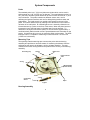
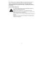
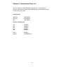
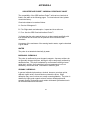
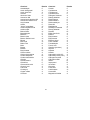
ORS Interface
Probe™
Installation and Operation Manual
Rev. 2 8/27/03 Part # ORS999006010
1
Table of Contents
Chapter 1: System Description……………………………………….…...p. 04
Function and Theory………………………………………………………p. 04
System Components……………………………………………………...p. 05
Chapter 2: System Installation…………………………………………….p. 07
Chapter 3: System Operation………………………………………...…...p. 08
Chapter 4: System Maintenance………………………………………….p. 10
Chapter 5: System Troubleshooting………………………………………p. 11
Chapter 6: System Specifications…………………………………………p. 12
Chapter 7: System Schematic……………………………………………..p. 13
Chapter 8: Replacement Parts List……………………………………….p. 14
Warranty and Repair………………………………………………………..p. 22
2
DOCUMENTATION CONVENTIONS
This manual uses the following conventions to present information:
An exclamation point icon indicates a WARNING of a
situation or condition that could lead to personal injury or
death. You should not proceed until you read and
thoroughly understand the WARNING message.
WARNING
A raised hand icon indicates CAUTION information that
relates to a situation or condition that could lead to
equipment malfunction or damage. You should not
proceed until you read and thoroughly understand the
CAUTION message.
CAUTION
A note icon indicates NOTE information. Notes provide
additional or supplementary information about an activity or
concept.
NOTE
3
Chapter 1: System Description
Function and Theory
The ORS Interface Probe™ is a hand held, battery powered device for
measuring depth to water or oil in tanks or wells. The ORS Interface Probe™
can be used in numerous applications including measuring oil and water levels in
monitoring wells, and obtaining accurate measurements of water levels in
cascading wells. The system is Factory Mutual Approved for Class 1, Division 1,
Group D applications.
This manual applies to ORS Interface Probes™ with part numbers 1068013,
1068015, 1068017, 1068018, and 1068021. These models differ only in tape
length and in the graduations on the front and back of the measuring tapes.
Measuring tape alternatives are as follows: 1068013 (100’ Engineering/Metric),
1068015 (200’ Engineering) 1068017 (30m Metric/Engineering), 1068018 (60m
Metric), and 1068021 (300’ Engineering). Engineering scales are in decimal feet
and Metric scales are in millimeters.
The ORS Interface Probe™ consists of a hydrocarbon/water sensing probe, a
measuring tape/probe cable and a housing into which the tape and probe can be
withdrawn when not in use. See pages 4 and 5 for a more detailed explanation
of these components, and see figure 1, for a picture of the entire assembly.
4
System Components
Probe
The standard probe is a 1" (25.4 mm) diameter cylinder which can be used in
wells as small as 1-1/8" (28.575 mm) in diameter. The small diameter probe is a
5/8” (.625 mm) diameter cylinder which can be used in wells as small as 1" (25.4
mm) in diameter. The probe contains two different sensor units, one for
detecting the liquid/air interface, and one for distinguishing between water and
hydrocarbon. The liquid sensor is an optical prism located on the end of the
probe. This sensor detects liquid by reacting to the differences in the indices of
refraction of air and liquids. An infrared light source is internally reflected to an
infrared detector by a prism on the face of the sensor. When the prism becomes
immersed in liquid, the light beam is refracted away from the detector. To
determine if the liquid is conductive (water) or non conductive (hydrocarbon), a
small Intrinsically Safe electrical current is passed between two electrodes on the
sensor. Current flow will occur only in conductive fluids such as water. The ORS
Interface Probe™ is capable of measuring oil slicks less than 1/16 of an inch
(1.5875 mm in thickness).
Measuring Tape
The specially coated measuring tape connects the probe with the housing
assembly and provides an accurate means of measuring the distance from the
well head or tank port to the air/water, air/oil or oil/water interface. The tape
contains all the wires running between the probe and the circuitry in the housing
assembly.
Grounding Clip
Handle
Brake Lever
Probe Protector
Tube
Casing
ON/OFF Switch
(Crank Handle)
Probe
Conductivity
Sensor
Prism
Wiper
Figure 1
Housing Assembly
5
The components of the weatherproof NEMA 3 housing assembly are shown in
figure 1. The housing includes a casing and reel to protect and deploy the
measuring tape and probe. The housing also has a Low Battery indicator, a
visual/audible alarm and a test button for the alarm. A grounding clip is attached
to the housing.
Intrinsic Safety & Approval
The intrinsic safety and approval of the ORS Interface Probe™ is
subject to the following requirements.
Batteries must be changed only in a non-hazardous location.
Batteries must be Duracell Type MN1500 (size AA). Substitution will
impair intrinsic safety and void approval.
When in operation, the unit must be grounded with the grounding clip
provided.
Substitution of components and/or improper use will impair intrinsic
safety and void approval.
6
Chapter 2: System Installation
Attach a grounding clip to a confirmed ground before lowering the probe. No
further preparation is required.
7
Chapter 3: System Operation
Taking a Measurement
To turn the unit on, unfold the crank handle away from the reel housing (see
figure 1). This activates a power switch inside the reel.
Before activating the probe, attach the grounding clip
to a suitable earth ground.
To verify that the unit is operational, press the test button on the face plate. If the
power is ON, the visual/audible alarm will be activated. A low battery condition
will cause the Low Battery indicator to be illuminated.
BEFORE REPLACING BATTERIES,
READ SECTION ON INTRINSIC SAFETY AND APPROVAL.
To release the probe, pull the protector tube outward from the reel casing. To
lower the probe, tilt the front of the reel housing forward and press the brake
release. The brake release is located just forward of the handle. The tape will
reel out as long as the brake release is pressed. Lower the probe into the well
taking care not to allow the probe or tape to rub against the well casing. Refer to
Appendix B for an alternative means of probe deployment.
When the probe contacts liquid, the visual/audible alarm on the reel will be
activated. An oscillating alarm indicates water, a continuous alarm indicates
hydrocarbon. To determine the exact thickness of a hydrocarbon layer, the
probe should be slowly lowered to the air/hydrocarbon interface until the alarm is
activated. With the probe at the exact point where the alarm comes on, read the
numbers on the tape to determine the distance from the top of the well head to
the air/hydrocarbon interface.
8
Battery Pack
Retaining Clip
Face Plate
(Removed)
Batteries
Switch
Electronics
Housing
Battery Pack
Crank Handle
Next, lower the probe through the hydrocarbon layer and well into the water. An
oscillating alarm will be obtained. The probe should then be raised slowly to the
hydrocarbon/water interface until the point is reached where the alarm changes
from oscillating to continuous. The thickness of the hydrocarbon layer is
determined by subtracting the first reading from the second reading.
The most accurate results are obtained by moving the probe as
slowly as possible.
It is important that the probe be removed from the fluid slowly. If
not, drops of fluid may remain on the probe tip giving a false
indication of liquid after it has been removed.
After taking a measurement, snap the protector tube shut so the wiper rests
against the tape. Release the brake and slowly reel in the tape until the probe is
just below the wiper. Do not allow the probe to bottom out against the wiper, as
this will apply stress to the tape and possibly damage connections at the probe.
Next, open the protector tube and gently reel the probe 2/3 of the way into the
tube. Forcibly reeling the probe all the way into the tube may stress or break the
measuring tape. Now, turn the entire ORS Interface Probe™ assembly upside
down so that the probe falls the rest of the way into the protector tube. Make
sure that the probe is entirely within the protector tube. Finally, close the
protector tube.
The ORS Interface Probe™ is equipped with an automatic shutoff circuit. If the
probe has not sensed liquid within 4 minutes from the time power is applied, the
unit will automatically switch to a low power mode. This prevents battery drain in
the event the power is left on accidentally. To restore power, place the handle in
the OFF position and then back to the ON position.
9
Chapter 4: System Maintenance
The ORS Interface Probe™ is designed to be virtually maintenance free. The
only maintenance required is cleaning off the reel and probe and periodic
replacement of the batteries.
After every measurement, the probe should be washed in Alconox detergent,
rinsed in distilled water, washed again in Alconox and rinsed for a final time in
distilled water. Also clean all accessible parts of the reel assembly. Under some
circumstances, a more aggressive cleaner may be required to prevent crosscontamination of wells. Before replacing the batteries, read section on intrinsic
safety and approval.
10
Chapter 5: System Troubleshooting
The ORS Interface Probe™ is a sealed unit and is not easily repaired in the field.
With the exception of replacing a damaged prism, any major malfunction should
be referred to the Customer Service Department at Geotech Environmental
Equipment Inc. (800) 833 - 7958 or (303) 320 - 4764.
To remove a damaged prism, use a ¾” (19 mm) wrench (hex socket 6 point) and
unthread the prism assembly from the probe bottom. A replacement prism
assembly is available by ordering Part Number 2060010.
To prevent water from entering the prism cavity, carefully dry the
probe before removing the old prism. Throughout the prism
removal and replacement procedure, hold the probe with the prism
pointed downward.
Installing the new prism assembly
Simply thread the prism into place and secure finger tight. Then use a ¾” (19
mm) wrench to firmly seat the o-ring. Be careful not to over tighten.
11
Chapter 6: System Specifications
Probe
Material:
Weight:
Diameter:
Length:
Probe waterproof to:
Maximum probe shock:
Conductivity sense range:
Minimum detectable hydrocarbon thickness:
304 Stainless Steel, Radel
4.6 oz / 130 grams
1 inch / 25 mm
6 ½” inches / 165 mm
100 psi / 6.9bar
10 G
> .78µS
.0312” / <.8 mm
Tape
Material:
Length/Weight:
kg)
100’ / 30 m
Kynar® coated Stainless Steel
7.7 lbs (3.5 kg) w/case 15.2 lbs (6.9
200’ / 60 m
300’ / 90 m
11.9 lbs (5.4 kg) w/case 22.0 lbs (10 kg)
15.8 lbs (7.2 kg) w/case 27.8 lbs (12.6
kg)
th
100 of a foot/100’
Per Federal Specification GGG-T-106E
Accuracy:
Reel/Frame
Size:
100’/30m
w/Case
200’/60m
w/Case
300’/90m
w/Case
Battery:
AA)
Self shut off time:
Output tone (hydrocarbons):
Output modulation tone (water):
13” H x 12” W x 3 ¼” D
330mm H x 300mm W x 80mm D
20” H x 14” W x 8” D
510mm H x 360mm W x 205mm
17” H x 16” W x 3 ¼” D
430mm H x 400mm W x 80mm D
25” H x 20” W x 8” D
630mm H x 510mm W x 205mm
19” H x 19” W x 3 ¼” D
480mm H x 480mm W x 80mm D
29” H x 22” W x 8 ½” D
730mm H x 560mm W x 210mm
9 VDC (Six, Duracell Type MN1500 size
4 minutes
500 Hz typ
3.5 Hz typ
Unit
Operating temperature range:
Storage temperature range:
Humidity:
32°F / 0°C to 140°F / 60°C
-40° to 170°F / 75°C
5-95% non-condensing
12
Chapter 7: System Schematic
13
Chapter 8: Replacement Parts List
This unit contains no field replaceable components. If the unit fails to
operate, contact your Geotech Sales Representative to troubleshoot further,
or return the unit for repair.
Carrying Case
100’/30m
200’/60m
300’
PPM132002
PPM132004
PPM132006
Unit w/o Carrying Case
100’
200’
300’
30m
60m
2068009
2068060
2068005
2068013
2068021
Prism
Manual
2060010
ORS999006010
14
APPENDIX A
ORS INTERFACE PROBE™ CHEMICAL RESISTANCE CHART
The compatibility of the ORS Interface Probe™ with various chemicals is
listed in the table on the following pages. For chemicals not listed, please
consult the factory.
Chemical resistance is rated as follows:
A: Good: at 20 degrees C.
B: Fair: Slight attack and absorption. Inspect and rinse after use.
C: Poor: Use the ORS Chemical Interface Probe™.
* Indicates that the probe material has not yet been tested specifically with
that chemical but the results can be predicted from tests with similar
chemicals.
A summary of the resistance of the sensing head to water, organic chemicals
is given below.
WATER
The probe is not attacked chemically by water.
INORGANIC CHEMICALS
The probe is unaffected by most inorganic reagents. Aqueous solutions do
not generally damage the prism, although it may be temporarily softened by
absorbed water. The prism is attacked by concentrated oxidizing mineral
acids (nitric, sulfuric, and hydrochloric) at room temperature but is not
affected by more dilute acids. Resistance to alkalis is good.
ORGANIC CHEMICALS
In general, aliphatic hydrocarbons, alcohols, benzene, petroleum spirits,
aliphatic organic acids, oils and fats do not attack the prism. Slight
absorption may occur but does not usually cause degradation. The prism is
attacked by highly polar organic solvents such as dimethysulphoxide,
aromatic amines, nitrobenzene, and certain chlorinated hydrocarbons such
as dichloromethane and chloroform.
15
Chemical
Acetaldehyde
Acetic Acid-glacial
Acetic Acid-10%
Acetone
Aluminum Salts
Ammonia- 880
Ammonium hydroxide-10%
Ammonium chloride-10%
Amyl Acetate
Aniline
“Arcton” propellants
Aviation hydraulic fluid
Aviation spirit
Barium Salts
Benzaldehyde
Benzene
Benzoic Acid
Benzen Sulfonic Acid
Bleach
Boric Acid
Brake Fluid
Brine
Butane
Butanol
Butyl Acetate
Calcium nitrate
Calcium hypochlorite
Carbon disulphide
Carbon tetrachloride
Chlorine
Chlorobenzene
Chloroform
Chlorosulfonic acid
Chromic Acid
Citric Acid
Cooking oil
Copper sulfate
Creosote
Results
C
A
A
C
A*
A
A
A
B
C
A*
B
A
A*
C
A
A
A*
A
A*
B
A
A
A
B*
A
A
B*
A
C
C
C
C*
A
A
A
A
A
16
Chemical
Cresols
Cyclohexane
Cyclohexanol
Cyclohexanone
Detergent Solutions
Dibutyl phthalate
Dichlorobenze
Dichloroethane
Dichloroethelyne
Diesel Oil
Diethylamine
Dimethyl Formamide
Dioctyl phthalate
Dioxane
Edible fats & oils
Ethanol
Ethyl Acetate
Ethyl Alcohol
Ethylene glycol
Ferric chloride
Formaldehyde
Formic Acid
Gasoline (premium)
Glycerol
Heptane
Hexane
Hydrochloric acid-10%
Hydrochloric acid (conc.)
Hydrogen Peroxide
Hydrogen sulfide
Iodine
Isopropanol
Iso-octane
Kerosene
Lactic Acid
Lead Acetate
Linseed Oil
Magnesium Sulfate
Results
C
A
A
C
A
A
C
C
B
A
A
C
A
B*
A
A
C
A
A
A
A
A
A
A
A
A
A
A
A
A
B
B
A
A
A*
A*
A
A
Chemical
Results
Chemical
Results
Mercuric chloride
Mercurous chloride
Mercury
Methanol
Methyl Ethyl Ketone
Methyl Chloride
Milk
Motor Oil
Nickel Salts
Nitric Acid-10%
Nitric Acid (conc.)
Nitrobenzene
Oils (Vegetable)
Oleic acid
Oleum
Oxalic acid
Perchloroethylene
Petrol
Petroleum Ether
Phenols
Potassium hydroxide-10%
Potassium hydroxide-50%
Propane
Pyridine
Silicon fluids
Silver nitrate
Soap solution
Sodium chloride
Sodium hydroxide-10%
Sodium hydroxide-50%
Sodium hypochloride
Sulfur dioxide
Sulfuric Acid-10%
Sulfuric acid (conc.)
A*
A*
A*
A
C
C
A
A
A*
A
C
C
A
A*
C
A
C
A
A
C
A
A
A*
C
A
A
A
A
A
A
A*
B
A
C
Sulfurous acid
Tar
Tartaric acid
Tetrahydrofuran
Toluene
Transformer oil
Trichloroethylene
Turpentine
Vaseline
Varnish
Water
Wax
White spirit
Wines and spirits
Xylene
Zinc salts
C*
A*
A*
C
C
A
B
A
A*
A
A
A*
A
A*
B
A*
17
APPENDIX B
INTERFACE PROBE TRIPOD MOUNT
This Interface Probe is equipped with a 1/4-20 threaded hole (on bottom of
frame assembly) for mounting on a standard photo or video tripod. This
feature allows the probe to be centered in the well and prevents the probe or
measuring tape from sustaining damage during deployment or recovery.
18
Some common decontamination solutions are listed below along with the
contaminants they are effective against:
Solution
Effective Against
Water
Short-chain hydrocarbons, inorganic compounds,
salts, some organic acids, other polar compounds.
Basic (caustic or alkaline) compounds, amines,
hydrazines.
Acidic compounds, phenols thiols, some nitro- and
sulfonic compounds.
Nonpolar compounds (such as some organic
compounds)
Dilute Acids
Dilute Bases
Organic solvents
The use of organic solvents is not recommended because:
1) Organic solvents can permeate and/or degrade the protective clothing and
2) They are generally toxic and may result in unnecessary employee exposure to
hazardous chemicals.
When in doubt, use a dish washing liquid detergent. As a decontamination
solution, it is readily available, is the safest of all the above, and is usually strong
enough if used generously.
The use of steam can also be effective for decontamination. A water-lazer
(pressurized water) is exceptionally valuable.
The following substances are noted for their particular efficiency in removing
certain contaminants or for decontaminating certain types of equipment.
Solution
Effective Against
Penetone
PCB Contamination (since penetone may also
remove paint, it is a good idea to spot-test before
use)
Liquinox
Contaminated pumps
Ivory liquid
Oils
Diluted HTH
Cyanides
Radiac
Isopropanol
Hexane
of
Zep
Alconox
Low level radioactivity
Biological agents (should not be used on rubber
products since it will break down rubber)
Certain types of lab or sampling equipment (use
hexane is discouraged due to its flammability and
toxicity)
General purpose cleaning
General purpose cleaning
19
Recommended Supplies for Decontamination of Personnel, Clothing
and Equipment
The list below contains recommendations for supplies which would be on
hand for the decontamination of personnel, clothing and equipment.
Depending on the site activities, not all of these items may be needed.
Alternatively, some additional items not listed here may be required.
• Drop cloths of plastic or other suitable material, such as visqueen, for
heavily contaminated equipment.
• Disposal collection containers, such as drums or suitably lined trash cans
for disposable clothing and heavily contaminated personal protective
clothing or equipment to be discarded.
• Lined box with adsorbent for wiping or rinsing off gross contaminants and
liquid contaminants.
• Wash tubs of sufficient size to enable workers to place booted foot in and
wash off contaminants (without a drain or with a drain connected to a
collection tank or appropriate treatment system).
• Rinse tubs of sufficient size to enable workers to place booted foot in and
wash off contaminants (without a drain or with a drain connected to a
collection tank or appropriate treatment system
• Wash solutions selected to wash off and reduce the hazards associated
with the contaminated wash and rinse solutions.
• Rinse solution (usually water) to remove contaminants and contaminated
wash solutions
• Long-handled, soft-bristled brushes to help wash and rinse off
contaminants.
• Lockers and cabinets for storage of decontaminated clothing and
equipment.
• Storage containers for contaminated wash and rinse solutions.
• Plastic sheeting, sealed pads with drains, or other appropriate method for
containing and collecting contaminated wash and rinse water spilled during
decontamination.
• Shower facilities for full body wash or at a minimum, personal wash sinks
(with drains connected to a collection tank or appropriate treatment
system).
• Soap or wash solution, wash cloths and towels.
• Clean clothing and personal item storage lockers and/or closets.
20
Decontamination Solutions to Avoid
Some decontamination solutions should be avoided because of their toxicity,
flammability, or harmful effects to the environment.
Halogenated hydrocarbons, such as carbon tetrachloride, should not be used
because of their toxicity, possible incompatibility, and some because of their
flammability.
Organic decontamination solutions should not be used on personal protective
equipment (PPE) because they may degrade the rubber or other materials
comprising the PPE.
Mercurials are sometimes used for sterilization. They should be avoided
because of their toxicity.
Chemical leaching, polymerization, and halogen stripping should all be
avoided because of possible complications during decontamination.
Sand-blasting, a method of physical removal, should be avoided because the
sand used on the contaminated object usually needs to be disposed of as
hazardous waste, a very costly proposition. Also, sand-blasting exposes
personnel to silica, a carcinogen.
Freon is known to be particularly effective for the cleansing of PCB's but its
effect on the ozone layer is extremely harmful. Its use is discouraged.
Strong acids or bases should not be used when cleaning metals and gaskets
or tools or other equipment because of the possibility of corrosion.
Disposal of Decontamination Solutions and Waste Water
All solutions and water used for decontamination must be collected. If lab
analysis indicates that the water and/or solutions exceed allowable
contamination levels, they must be treated as hazardous waste.
Alternatively, the solutions and water may be treated on-site to lower the
contamination levels and render them non hazardous.
Containers such as 55-gallon drums should be available for storage of
wastes.
Spent decontamination solutions can be collected by using heavy-duty plastic
sheets, visqueen sheets, kiddie pools, or if needed, a larger containment
basin. The decontamination of equipment must be performed on the sheets
or in the basins. They could be placed on a slight angle so that the spent
decontamination solutions drain into a collection basin or drum.
21
The Warranty
For a period of one (1) year from date of first sale, product is warranted to
be free from defects in materials and workmanship. Geotech agrees to
repair or replace, at Geotech’s option, the portion proving defective, or at
our option to refund the purchase price thereof. Geotech will have no
warranty obligation if the product is subjected to abnormal operating
conditions, accident, abuse, misuse, unauthorized modification, alteration,
repair, or replacement of wear parts. User assumes all other risk, if any,
including the risk of injury, loss, or damage, direct or consequential,
arising out of the use, misuse, or inability to use this product. User
agrees to use, maintain and install product in accordance with
recommendations and instructions. User is responsible for transportation
charges connected to the repair or replacement of product under this
warranty.
Equipment Return Policy
A Return Material Authorization number (RMA #) is required prior to
return of any equipment to our facilities, please call our 800 number for
appropriate location. An RMA # will be issued upon receipt of your
request to return equipment, which should include reasons for the return.
Your return shipment to us must have this RMA # clearly marked on the
outside of the package. Proof of date of purchase is required for
processing of all warranty requests.
This policy applies to both equipment sales and repair orders.
FOR A RETURN MATERIAL AUTHORIZATION, PLEASE CALL OUR
SERVICE DEPARTMENT AT 1-800-833-7958 OR 1-800-275-5325.
Model Number:
________________
Serial Number:
________________
Date:
________________
Equipment Decontamination
Prior to return, all equipment must be thoroughly cleaned and
decontaminated. Please make note on RMA form, the use of equipment,
contaminants equipment was exposed to, and decontamination
solutions/methods used.
Geotech reserves the right to refuse any equipment not properly
decontaminated. Geotech may also choose to decontaminate equipment
for a fee, which will be applied to the repair order invoice.
22
NOTES
23
NOTES
24
NOTES
25
26
Geotech Environmental Equipment, Inc
8035 East 40th Avenue Denver, Colorado 80207
(303) 320-4764 ● (800) 833-7958 ● FAX (303) 322-7242
email: [email protected] website: www.geotechenv.com