1
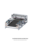
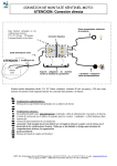
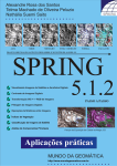
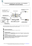
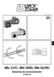
MATTRESSES WRAPPING MACHINE ME 105
INSTALLATION, USER AND MANTENIANCE MANUAL
NOTIFICATION OF CE MARKING
The Manufacturer: MERELLO Ingenieros, S.L.
c/Horcajo 20, nave 23
PINTO – 28320 – MADRID - SPAIN
Declare that the product: mattresses wrapper machine ME-105 s/n 1393
Has been developed in accordance with the European Directive 98/37/CE (22nd
June 1.998) and shows compliance with the Normative EN414. EN292,
EN1050, EN945, EN418 and EN1088 when used as directed by the
appropriate documentation
Signed: Miguel Merello Arvilla, industrial engineer
Madrid, July 2012
INSTRUCTION MANUAL
ME-105
2
1. GENERAL MACHINE DESCRIPTION
The machine ME 105 wraps automatically every kind of mattresses (springs, latex, foam,…)
from polyethylene rolls. The machine provides advance of the mattress trough the film and
adjusts itself to the appropriate measures. The finished mattress is ready to be stocked
The machine is compound by the following elements:
S9
S8
S7
M5
EM 2
S6
S5
FC 0
FC1
FC
2
S4
S1
M6
BOX 2
M7
BOX 1
S2
M1
BOX 3
M3
M2
M4
M O D U LE 3
M O D U LE 2
M O D U LE 1
Module nº1: Mattress In-feed: receive the mattress, put it on position for wrapping and measures
the length for adjust the corresponding sealing bars distance. The machine detects a new mattress
automatically and starts moving the in-feed conveyor. This module contains the upper and lower
rolls of film. For sincronice with in-feed lines, Y15 output is ON when the machine is ready
Module nº2: middle sealing: receive the enfold mattress from the previous module, seals all along
and separates the bag from the rolls, cutting it by blade
Module nº3: lateral sealing: receive the wrapped mattress from the previous module, seals both
sides, cut the waste of film by blade and give the mattress away.
Control cabinet: keeps the electrical and electronic components that provide the control of the
machine. A screen allows the man-machine dialogue, input parameters and show error messages.
The position at modules 1, 2 and 3 are measured by
contact-free devices that allow the machine to know
the exact position at every moment, as well as to
move to the rigth position without reset.
The machine complies with safety requirements of
CE as expressed on last chapter
TECHNICAL DATA
AERIAL NOISE: 70 dB(A)
WEIGHT MODULE 1: 1.400 Kg
WEIGHT MODULE 2: 800 Kg
WEIGHT MODULE 1: 1.600 Kg
INSTRUCTION MANUAL
ME-105
3
2. MACHINE INSTALATION
Every element of the machine has its own adjustable legs that allow the installation in any surface
Main job during installation consists on
leveling the machine and couple the
different modules. For this it is
recommendable a burble level
For electrical connections, each module
has cables to connect directly to the control
cabinet and between them. For more
information, see the scheme at the end of
the manual
The machine spends about 4 KW (two
phases electrical energy 220 VAC) while
seals and about 40 l/min. of dry, clean
compressed air at 6 bar.
INSTALLATION PROCEDURE
1.- allocate the module nº1 on its final
position and level
2.- allocate the module nº2 besides the nº1.
Put it to level and align both
3.- bring the module nº3 near the nº2,
leaving 1 m of free space between both
4.- connect cables C23 and C32 to box 3,
following scheme attached
5.- install the waste ramps
6.- install the sealing bars
7.- move the module nº3 to its final position besides nº2. Put it to level and align both
8.- install the fix and the movable ascending ramps
9.- install the lateral guards
10.- install and plug the EMERGENCY WIRE
11.- connect cables C2 and C3 to the control cabinet, following the schemes attached
12.- put the machine under voltage (220 VAC). Don’t forget the frame ground to earth
13.- introduce a mattress and effectuate a complete cycle without film. Verify everything works
14.- put the upper and lower reels of film (see section 3) and make a join between them
15.- introduce a mattress. See section 6 for fine adjustment
• SYNCHRONIZING WITH PREVIOUS LINES: the green light (Y15) on the control
cabinet lights when the machine is ready to accept a new mattress.
• SYNCHRONIZING WITH FOLLOWING LINES: the mattress will not leave the
INSTRUCTION MANUAL
ME-105
4
machine if the input signal X25 remains ON
INSTRUCTION MANUAL
ME-105
5
3. LOADING OF THE FILM AND STARTING UP
Place a roll of polyethylene (max. 150 Kg.) on the upper pair of rollers and other one on the
lower pair, keeping the correct side for welding
NOTE: some printed rolls will not join by the printed face due to the chemical
treatment received.
The same could occur with re-enforcement rolls for the top or bottom of the
mattress, because they will be join for the both faces
If this kind of problem appears, please ask your film provider
For the correct guidance of the
film, see the figure attached
The film surface tension
depends on the adjustment of
the passing trough lever. This
adjustment is the same for
every kind of mattress and
must be carried out with the
lightest to be wrapped. In order
to give more tension to the
final bag, you can operate over
the extra advance time on the
keyboard (see chapter nº 5)
When change a roll, it is
necessary to make a seal along
the upper and lower rolls. Pull
the film trough the guides (by
hand or acting over the plastic
lever) and press the key
‘CENTRAL SEAL’ (see
chapter nº 5)
After these adjustments, press
the START/STOP button to put
the machine ready to work
Please note that the machine will not work while any of the doors stay opened or the
emergency stop is pressed. The screen and lights will indicate this situation
INSTRUCTION MANUAL
ME-105
6
ME-104: PLASTIC FILM INSTALLATION
INSTRUCTION MANUAL
ME-105
7
4. CYCLE OF THE MACHINE
As a safety measure (CE), the machine won’t be ready to work after turn it ON until the
START/STOP button is pressed. After this, the green light on this button will remain ON and
the machine will work while ON (until a new acting over the button will be executed or an
alarm will occur).
By pressing the START/STOP button twice, the machine will perform a step by step cycle,
which allows analyzing or introducing adjustments
When the machine is turned OFF, it loses any information about the actual cycle. Due to that,
after turn it ON you should verify that there are not half wrapped mattresses on any of the
modules
The machine can vary between different working modes that can be selected on the screen and
act in the following ways:
WITH/OUT PRESS M3: select whether or not the press on the 3rd module is going to work.
This press is intended to approach the borders of the mattress and increase the adjustment of the
bag
A special input (X 3) is also provided for remote exchange of the press estate, and can be wired
from 24Vdc direct to the PLC. When activated, the second Xtra-advance is applied instead of
the first and the press is annulated for the mattress being in-feed.
WITH/OUT WHEELS M1: select whether or not the wheels on the 1st module are going to
work. The wheels are intended to catch the mattress against the conveyor for assure the
advance trough the machine.
WITH/OUT WHEELS M2: idem for second module
BEFORE/LATER ACT. WHEELS M2: select when the wheels on the second module must be
deactivated. BEFORE the welding bar means more adjusted bags and less wrinkles. AFTER
the welding bar can be necessary with very light mattresses
WITH/OUT SEAL SIDES: select whether or not the up and down sides of the mattress are
going to be sealed. Normally they must to be, but in special cases (rolling bags, foam,…) they
must to be opened
The machine controls the sealing temperature by software. The program on the machine has a
temperature simulator that compensate the accumulative heat when is used a high rates. This
value increases proportionally during welding and decreases exponentially the rest of the time.
At any time, the heating time programmed is reduced in function of the value of this
simulation, avoiding the raise of the temperature on bars
By pressing the EMERGENCY STOP or pulling the EMERGENCY WIRE the energy is
removed from the actuators, every movements of the machine are cancelled and the machine
INSTRUCTION MANUAL
ME-105
8
status is moved to STOP. After release it, the energy appears again but the machine remain
stopped until START/STOP button is pressed. Then, the cycle will resume to the previous point
(first, it’s necessary to remove the causes of the problem and realize if the mattress need to be
re-introduced. In this case, the best is turn the machine OFF an the ON to start to work from the
beginning)
By open any of the doors, every movements of the machine are cancelled and the machine
status is moved to STOP. After close it, the machine remain stopped until START/STOP button
is pressed. Then, the cycle will resume to the previous point
The meanings of the lights are:
• Green light: the machine will accept a new mattress to wrap
• Yellow light blinking: the machine is working at any point
• Yellow light steady: the machine has been stopped by the green button, in the middle of
a cycle
• Red light blinking: emergency stop is pressed or emergency wire is pulled or a door is
opened or an alarm has occurred. The screen shows the status
• Red light steady: emergency has been eliminated, but the machine is not working until
START/STOP will be press
INSTRUCTION MANUAL
ME-105
9
5. MANTENIANCE
EVERY WEEK: remove the waste from the cutting cylinder case in order to avoid damages
EVERY WEEK: check the oil level on the compressed air filter. Refill if necessary
EVERY MONTH: clean the air filter on the control cabinet
EVERY MONTH: test the differential switch, by acting over the TEST button
• CARE OF THE BLADES AND TEFLON COVERS
The blades that cut the film are maintenance free and under normal situations last a lot. When
the blade results damaged it’s necessary to exchange for a new one. For replace the blade,
dismount the cover, untaught and pull carefully the old one and insert the new one
The Teflon covers last between 30.000 and 100.000 processes, depending on the gross of the
film and the heat conditions. When they are half used up, silicone sprayed could help to last
longer.
For covers substitution, please use self-adhesive 0,15 mm thick Teflon fabric
•
REPARATION OF RODLESS CYLINDERS:
3
2
1
5
1.
2.
3.
4.
5.
REPAIR KIT
air connection
end caps
out seal strip
inner seal strip
shuttle
4
INSTRUCTION MANUAL
ME-105
10
6. FINE ADJUSMENT
Even though the machine has been tried at factory, the final conditions can differ. These are some
different adjustment that allow to achieve the most perfect bag
TERMICAL ADJUSTMENT OF THE SEALS
By varying the sealing parameters, the machine can join any kind of film. The criterion depends
on the final goal:
- higher speed: ▲power, ▼time heating, ▼time cooling
- less electrical energy, more duration of covers: ▼power, ▲time heating
- more esthetic seals: ▲time cooling
- thicker film: ▼power, ▲time heating, ▲time cooling
- very inelastic film: ▼time cooling, ▲time waiting
ADJUSTMENT OF THE BAG
The final adjustment of the bag to the mattress depends on several points:
- how long the mattress advance over the central seal bar
- how strech is the film during the tie up
The fastest way to change the bag adjustment is by acting on the first point, directly on the
keyboard. In the line EXTRA ADVANCE change the value (cents of second that the mattress will
advance over the seal bar). Note that a too low value can provoke the mattress to be catch by the
bar
The stretch of the film must be between two limits: no too high, because can broke the join at one
or both sides, and no too loose, because can present unwinding problems. Note that the stretch is a
combination of the position of the lever, the relative speed of the film respect to the advance of the
mattress (adjustable by inverter) and the relative speed of the film respect to the bar when moves
down. For initial adjustment, keep the speed of the rolls as similar as posible to the advance of
mattress (watch the lever angle to stabilizate), and adjust the speed of the arm to the desired
stretch
The position of the central seal can be moved by changing one of the film stretch
LONGITUDINAL ADJUSTMENT OF THE BAG
When wrapping mattresses thicker than 10 cm, the press compresses its top and bottom in order to
approach the border before sealing, leaving a better adjusted bag.
On depending on the kind of film and mattress, to achieve this could be easier by keeping some
distance between the mattress and the sealing bar. This adjustment is made by:
- fix side: move the fix end on the module nº1 in order to approach or separate the mattress
- movable side: change the data on the keyboard called LATERAL ADJUSTMENT (bigger
values provoke bigger separation) or move the end-detectors
SPECIAL ADJUSTMENT WHEN USING BOOT SYSTEM
INSTRUCTION MANUAL
ME-105
11
In order to keep the same strenght on every roll, is very recommendable to reduce the rolls speed a
little. This way, the coneyor will help for unwinding the rolls, avoiding different speeds
Also, the parameter ‘Time retro roller’ can be increased with the same purpose
INSTRUCTION MANUAL
ME-105
12
7. TOUCH SCREEN
The touch screen is placed on front of the electrical cabinet, and it allows the following
functions:
• shows error and status messages
• introduce different working modes
• introduce control parameter
• activate elements of the machine
PASSWORD: to operate other than the main screen, a password will be requested. There are 2
different passwords that give access to 2 different levels:
7791: allows to access only to the first DATA screen, with frequent used parameters. Value:
1977: allows to access to all the screens: DATA and TEST
The main screen shows the status message. After an alarm occurs, the message line explains the
alarm that occurs. These messages are:
• Emergency stop (even after it’s been released)
• Door opened (even after it’s been closed)
• Inicializing: while moving the machine to the initial position
• Ready: the machine will accept a new mattress
• Working: there is a mattress in-feed
• Stopped: the START/STOP button was pressed and the machine is waiting
• Error on D3/D4: the length detectors D3 or D4 on M1 (when included) have
been activated with no cycle. They could be broken or to high sensibility. Check
the problem and press START/STOP button to resume
• Error on S3: the movement of the central sealing bar hasn’t reach the final
position. The reason could be: the bar has catch a mattress, the detector has
moved a little down, or the order to move didn’t activate the electro valve
• Error on phase 2: the wrap of the mattress exceeds the time limit. After check
the problem, move the mattress up to pass the sealing bar (F3 key) and press
STAR/STOP button to resume the cycle
• Technical stop: contact technical service
INSTRUCTION MANUAL
ME-105
13
The effect of the function keys is the following (the machine should be in STOP mode):
• Seal C: make a seal on the central bar.
• Seal L: make a seal on the side bars
• Belts: advance of conveyor nº 2 y 3
• -Film: retro of the film rollers
• <Bar 2: advance of movable seal bar
• >Bar 2: retro of movable seal bar
The rest of the information on other screens show parameters that can be changed. To change a
value, touch it directly. Then a keyboard appears on the screen and let you write the new value
(press ENTER for finish). If the value is not between the acceptable ranges, the display will
reject it
DATA MENU:
• ALTERNATE BUTTON LAT.SEAL: when activated, the seals on the 3rd module
(lateral seals) are made on each bag. When deactivated, the mattress leaves the machine
directly from the first seal
INSTRUCTION MANUAL
ME-105
14
• ALTERNATE BUTTON PRESS M3: when activated, the press on the 3rd module
descends to approach the edges of the mattress and increase the adjustment of the bag before
sealing. Don’t use it with hard beds (wood)
• ALTERNATE BUTTON PRESS M2: when activated, the wheels on the 2nd module
descend to increase the pressure of the bagged mattress against the belt, avoiding it to slip
• ALTERNATE BUTTON bef/aft: when BEFORE and PRESS M1 are activated, the
wheels on the 2nd module release before seal, to avoid wrinkles. When AFTER (and PRESS
M2) are activated, the wheels keep connected to ensure that the mattress is not catch by the
sealing bar.
• BUTTON PARAMETER: give access to the parameter menu (see below)
•
BUTTON MEASURES: give access to the measures menu (see below)
• T HEAT CENTER: time in tenth of second during which power is applied to the central
welding bar. This value will be reduced by the temperature compensation system (see below).
The amount of power can be regulated in the control cabinet P1. Valor aprox.: 25-50
NOTES:
The grosser the film is, the higher this value must be
Too high power values will reduce the Teflon covers life
Too high values will increase the cycle time
• T COLD CENTER: time in tenth of second after heating during which the bar stay down
to allow the film to solidify. Aprox.: 10-40
• T HEAT LATS: time in tenth of second during which power is applied to the lateral
welding bar. This value will be reduced by the temperature compensation system (see below).
The amount of power can also be regulated in the control cabinet P2. Valor aprox.: 30-60
• WAITING CENTER: time in tenth of seconds that the mattress is waiting for the bar of
Module 2 to open. Aprox.: 5-10
• WAITING SIDES: time in tenth of seconds that the mattress is waiting for the bars of
Module 3 to open. Aprox.: 5-10
• TIME CUTTER CENTER: the first value is the time in tenth of seconds that the central
cutter will wait to activate (aprox 5). The second, the time during which the blade travel
trough the film in the central bar to separate the bag. After this time, the blade will back to its
position. Aprox.: 20-30
• TIME CUTTER S: the first value is the time in tenth of seconds that the lateral cutter
will wait to activate (aprox 5). The second, the time during which the blade travel trough the
film in the side bars to separate the rest of film. After this time, the blade will back to its
INSTRUCTION MANUAL
ME-105
15
position. Aprox.: 20-30
• XTRA ADVANCE: time in cents of second while the mattress stays advancing over the
central welding bar. A higher value induces bigger advance before soldering, and the bag will
be looser. The first value will be applied by the machine when X13 is OFF (the second, when
ON). Aprox. values: 10-30
• LENGTH ADJUSTMENT: time in cents of seconds (+/-) that is subtract from the
measure in Module nº1 to adjust the aperture of the bars in Module nº3. This adjustment can
also be achieved by approaching or separating the inductive detectors of this parts. A positive
value will provoke a bigger separation in module nº3 Aprox.: 0
• ADVANCE PRESS M3 (when equipped): advance of the press in Module nº3 over the
mattress to approach their faces and assure the traction. After this advance, the welding bar
down to make the join. Aprox.: 7-12
MEASURES MENU
• BUTTON DEFAULT: load the default parameters value. Also allows to change the
language of the messages
• SELECTOR AUTO/MANUAL: select between automatic adapt to the measures of the
mattress or not
• BUTTON UNSTICK: provokes the machine to make a small movement of the rollers in
order to unstuck the film for the next mattress
• BUTTON STACKER: provokes the machine to use the output stacker (when available).
The button besides will make the machine stop when there is no chart or not
INSTRUCTION MANUAL
ME-105
16
• MINIMUM LENGTH: maximum advance of the measuring bar in module nº1 to avoid it
to shock against the conveyor. The mattress will be wrapped even if is littler than this. Aprox.:
250
• SIZE M2: value relative to the length of the second conveyor, in order to activate the third
conveyor when the mattress exceeds the corresponding size. A bigger makes the third
conveyor to start later. Aprox.: 40-60
• SIZE M3: value relative to the distance between bars in module nº1 and bars in module
nº3, in order to calculate the necessary advance of the mattress. A bigger value provokes the
mattress to advance more. The right value makes the mattress to stop in the beginning of the
module nº3. Aprox.: 200-300
• BIGGER-SMALLER: values to distinguish if two consecutives mattresses are the same
length or not. Minor is the negative difference under which the bar in module nº3 will need to
re-locate. Mayor is the positive one. If this value is big enough two different mattresses will
be processed as if were the same length. Aprox: -6, +6
• BLOWER M1: the first number is the delay in tenth of seconds for the blowers in M1 to
be activated to help removing wrinkles. The second time is the duration of the blow,
adjustable to avoid the bag hit the lateral bar
• BLOWER M3: time in tenth of seconds during which the blower in M3 is activated to
help removing waste. Aprox.: 10-20
• SIZE>2M: the first value is the number that, when exceeds, provokes the machine to
make two seals instead of one. The second value show the wide of the present mattress, and
helps to calculate the first
• ADVANCE1 >2M: shows the time in cents of second that the mattress will advance for
make the first seal, if the mattress is >2m (previous point). Then, the mattress will advance up
to the normal position to make the second seal
• GAIN F: value (center and sides) that decreases the simulated temperature while not
heating. It is apply each two seconds subtracting a division of the value (Temp/value) from the
simulated temperature. Aprox.: 8-15
INSTRUCTION MANUAL
ME-105
17
PARAMETER MENU:
• ALTERNATE BUTTON PRESS M1: when activated, the wheels on the 1st module (infeed conveyor) descend to increase the pressure of the mattress against the belt, avoiding it to
slip
• ALTERNATE BUTTON RAMPS: when activated, the ramps on the 2nd module ascend
before sealing to avoid the film to retract on the mattress advance. Is useful for sticky film
• T-RETRO M2: time for the second conveyor to move backwards before sealing to
increase the adjustment of the bag
• MAX. PRESS M3: the first value shows the maximum number of teeth that the press
will count before activate the seal, even if it is not mattress detected. Is only for sizing
purposes, the second number shows the number of teeth already counted, and helps to
calculate the first
• TIME PRESS M1: time in tenth of seconds during which the wheels over conveyor in
Module nº1 push on the mattress to assure the traction. After this time, the wheels up to avoid
a shock against the conveyor. Aprox.: 10-20
• DELAY PRESS M2: time in tenth of seconds during which the wheels over conveyor in
Module nº2 wait to push on the mattress to assure the traction. This permit the mattress to start
advance during wrapping. Aprox.: 10-20
• TOTAL PRODUCTION: shows the number of units processed by the machine from the
first day to now.
INSTRUCTION MANUAL
ME-105
18
TEST MENU:
Give access to every output on the PLC, for monitoring and modify (some of them need to put
the PLC in STOP mode to be accepted). Useful for maintenance actions
INSTRUCTION MANUAL
ME-105
19
8. INSTRUCTIONS FOR SAFETY
♦ The load of the rolls is dangerous and need two or more people
♦ The doors of the machine should remain closed. When a door is opened, the cycle stops and
waits for the START/STOP button
♦ The machine detects automatically the arrive of a new mattress, and put the conveyor to move
so, therefore no objects must be put on it to avoid obstructs and accidents
♦ The cuts are made by blade which could cause injuries in hands and arms. The operation of
exchange must be realized protected with gloves
♦ The seals are achieved by heating. The wrong use of the bars can cause burn on hands or arms
♦ The machine is intended for wrapping mattresses. The use for wrapping other kind of things
can result in injuries or accidents
INSTRUCTION MANUAL
ME-105
20
9. PART LIST
FASE
1
1
1
1
1
1
1
1
1
1
1
1
1
1
1
1
1
1
1
1
1
1
1
1
Plano
1
2
3
4
5
6
7
8
9
10
11
12
13
14
15
16
17
18
19
20
21
22
23
24
ID
UCF205
UCP204
FC1
PP1i
BIS
FCBIS
FC0
PLACA1
BANDA1
UCPA206
M2
M1,4,5
EV1,2,3
CIL0
PP1d
MANI
FC1e
GUB1
RU1R
D3,D4
S2,S7
RUL
FC2
CIL1
Cant
16
2
1
2
4
2
1
2
1
4
1
3
3
2
1
2
1
1
2
2
2
8
1
1
Descripción
Bearing flange type UCFL 205
Bearing bridge type UCP 204
Photocell barrier BANNER BOS 012C w/mirror
Polycarbonate door smoked 620x1120x8
Polypropylene door joint
Safety switch Telemecanique XCSPL591
Photocell barrier auto reflexive BALLUF BOS 0123
Steel entrance plate
Conveyor belt PVC NAB-10ELBV 2000X3115
Bearing bridge type UCPA 206
Motoreducer Bonfiglioli VF44 A 20 P71 B14 B3, 0,37KW i=20
Motoreducer Bonfiglioli VF44 P1 20 P71 B14, 0,37KW i=20
Electrovavle SMC 5/2 1/8 24 VDC G6250
Cylinder SMC ISO 32 80 D.M
Polycarbonate door smoked 620x1120x8
Door latch ref 5608
Mirror photocell barrier
Steel plastic guide Ø50 x 3050
Nylon wheel Ø200
Steel detector with inductive
Film tensor Ø20 with inductive
Roller for film Ø108 x 3050
Photocell programmable BANNER QS18EP6DB
Cylinder SMC ISO 32 160 D.M
2
2
2
2
2
2
2
2
2
2
2
2
2
2
2
2
2
2
2
2
2
1
2
4
7
8
9
10
11
12
13
14
15
16
17
18
19
20
21
22
23
24
PP2d
CIL4
CP21
CP22
CIL3
CIL6
S3
PP2t
FCBIS
M7
ESET
NICR408
CELO2010
NEOP2010
BL
PBL
CIL5
BANDA2
RU2L
UCPA206
UCFL205
2
2
1
1
2
2
1
2
4
1
4
6
6
6
1
1
1
1
2
4
4
Polycarbonate door smoked 765x880x8
Cylinder SMC ISO 40 320 D.M
Guards sealing bar blade side
Guards sealing bar connections side
Cylinder SMC ISO 63 400 D.M
Cylinder SMC ISO 25 50
Inductive detector Univer ISO63
Polycarbonate door smoked 865x880x8
Safety switch Telemecanique XCSPL591
Motoreducer Bonfiglioli VF44 P1 20 P71 B14 B3, 0,37KW i=20
Baquelite resistance terminal
Resistance NiCr 4x0,8 (1m)
Celotex base spline 20x10 (1m)
Neoprene self-adhesive 20x10 (1m)
Trapezoidal blade (10 units)
Blade base
Rodless cylinder SMC Ø16x3050 S1004163050
Conveyor belt PVC NSL-10ELAV 2000X3115
Nylon wheel Ø200
Bearing bridge type UCP 206
Bearing flange type UCFL 205
3
3
3
1
2
3
PLACA3F
PRT
BANDA3
1
2
1
Steel fix ramp
Polyurethane plate for waste
Conveyor belt PVC NSL-10ELAV 2000X4635
INSTRUCTION MANUAL
ME-105
21
3
3
3
3
3
3
3
3
3
3
3
3
3
4
5
6
7
8,9
10
11
11
12
13
14
15
16
PLACA3M
M3
S4
LGR15
PP3
PM3Z14
CP3
CIL8
CIL11
CIL7
UCPA206
M6
S5
INSTRUCTION MANUAL
1
1
1
2
4
4
2
2
4
4
4
1
1
Steel movable ramp
Motoreducer Bonfiglioli VF44 A 20 P71 B14 B3, 0,37KW i=20
Inductive detector RESCHNER M12 4mm 30VDC
Lineal guide HIWIN LGR15 w/bearing LGH15
Polycarbonate door smoked 910x880x8
Rotative gear M3 Z=14
Guards sealing bar lateral side
Rodless cylinder SMC Ø16x2300 S1004162300
Cylinder SMC ISO 40 400 D.M
Cylinder SMC ISO 40 320 D.M
Bearing bridge type UCPA 206
Motoreducer Bonfiglioli VF44 P1 20 P71 B14 B3, 0,37KW i=20
Switch detector with Ø45 wheel
ME-105
22
9. LIST OF MATERIALS
FASE
1
1
1
1
1
1
1
1
1
1
1
1
1
1
1
1
1
1
1
1
1
1
1
1
Plano
1
2
3
4
5
6
7
8
9
10
11
12
13
14
15
16
17
18
19
20
21
22
23
24
ID
UCF205
UCP204
FC1
PP1i
BIS
FCBIS
FC0
PLACA1
BANDA1
UCPA206
M2
M1,4,5
EV1,2,3
CIL0
PP1d
MANI
FC1
GUB1
RU1R
D3,D4
S2,S7
RUL
FC2
CIL1
Cant
16
2
1
2
4
2
1
2
1
4
1
3
3
2
1
2
1
1
2
2
2
8
1
1
Descripción
Rodamiento tipo brida UCFL 205
Rodamiento tipo puente UCP 204
Emisor fotocélula barrera Telemecanique XUK-2AKSNL2T
Puerta policarbonato humo 620x1120x8
Bisagra puerta polipropileno
Interruptor de seguridad Telemecanique XCSPL591
Detector fotoeléctrico Telemecanique XUK-5APANL2
Guía de entrada inoxidable
Banda PVC NAB-10ELBV 2250X3115
Rodamiento tipo silleta UCPA 206
Motoreductor Bonfiglioli VF44 P1 20 P71 B14 B3, 0,37KW i=20
Motoreductor Bonfiglioli VF44 P1 20 P71 B14, 0,37KW i=20
Electroválvulas Univer 5/2 1/8 24 VDC G6250
Cilindro Univer ISO 32 80 D.M fijación horquilla
Puerta policarbonato humo 620x1120x8
Cierre puerta bisagra ref 5608
Receptor fotocélula barrera Telemecanique XUK-2APANL2R
Guía plástico tubo acero Ø50 x 3050
Rueda nylon acanalada Ø200
Placa inoxidable detección medidas con inductivo
Tensor plástico Ø12 con detector inductivo
Rodillo portabobinas Ø108 x 3050
Detector fotoeléctrico Telemecanique XUM-5APANL2
Cilindro Univer ISO 32 160 D.M fijación horquilla
2
2
2
2
2
2
2
2
2
2
2
2
2
2
2
2
2
2
2
2
2
1
2
4
7
8
9
10
11
12
13
14
15
16
17
18
19
20
21
22
23
24
PP2d
CIL4
CP21
CP22
CIL3
CIL6
S3
PP2t
FCBIS
M7
ESET
NICR408
CELO2010
NEOP2010
BL
PBL
CIL5
BANDA2
RU2L
UCPA206
UCFL205
2
2
1
1
2
2
1
2
4
1
4
6
6
6
1
1
1
1
2
4
4
Puerta policarbonato humo 765x880x8
Cilindro Univer ISO 40 320 D.M fijación horquilla
Carcasa protección lado cuchillas
Carcasa protección lado bornero
Cilindro Univer ISO 63 400 D.M fijación horquilla
Cilindro Univer ISO 25 50 fijación horquilla
Detector inductivo Univer ISO63
Puerta policarbonato humo 865x880x8
Interruptor de seguridad Telemecanique XCSPL591 (XCSPL71)
Motoreductor Bonfiglioli VF44 P1 20 P71 B14 B3, 0,37KW i=20
Bornero baquelita terminal resistencia
ResistenciaNiCr 4x0,8 (1m)
Tira de Celotex ranurada 20x10 (1m)
Tira de Neopreno autoadhesivo 20x10 (1m)
Cuchilla trapezoidal
Portacuchillas
Cilindro sin vástago Univer Ø16x3050 S1004163050
Banda PVC NSL-10ELAV 2250X3115
Rueda nylon Ø200
Rodamiento tipo silleta UCPA 206
Rodamiento tipo brida UCFL 205
3
3
3
3
1
2
3
4
PLACA3F
PRT
BANDA3
PLACA3M
1
2
1
1
Rampa fija inoxidable
Plancha poliuretano recoge retales
Banda PVC NSL-10ELAV 2250X4035 (4635 p/EXTRA WIDE)
Rampa móvil inoxidable
3
3
3
3
3
3
3
3
3
3
3
5
6
7
8,9
10
11
12
13
14
15
16
M3
S4
LGR15
PP3
PM3Z14
CP3
CIL11
CIL7
UCPA206
M6
S5
MANUAL USUARIO
1
1
2
4
4
2
4
4
4
1
1
Motoreductor Bonfiglioli VF44 P1 20 P71 B14 B3, 0,37KW i=20
Detector inductivo RESCHNER M12 4mm 30VDC
Guía lineal HIWIN LGR15 con patines LGH15
Puerta policarbonato humo 910x880x8
Engranaje Piñón M3 Z=14
Carcasa protección lateral lado cuchillas
Cilindro Univer ISO 40 400 D.M fijación horquilla
Cilindro Univer ISO 40 320 D.M fijación horquilla
Rodamiento tipo silleta UCPA 206
Motoreductor Bonfiglioli VF44 P1 20 P71 B14 B3, 0,37KW i=20
Final de carrera electro mecánico rueda Ø45
ME-105
24
MANUAL USUARIO
ME-105
26
MANUAL USUARIO
ME-105
27
USER’S MANUAL
ME-105
29
USER’S MANUAL
ME-105
30
USER’S MANUAL
ME-105
31
LIST OF DE MATERIALS
Referencia
a1
a2,a3
D
g1
f1
PLC
16XY
c1-c2
p1-p2
v1- v7
m1- m7
FC0
FC1
FC2
D3,D4
S3
S5
S1,2,4,6,7
ev20-32
vent
EM1
EM2
PT1,2
RS
R
Descripción
Interruptor magneto térmico monofásico 6 A
Interruptor magneto térmico monofásico 25 A
Interruptor diferencial 2p 40A, 30 mA
Interruptor general trifásico 2x40 A
fusible Φ10, 25A
Autómata programable FX1N 40MTDSS
Módulo de salidas FX16YET
Contactor trifásico 24 VDC 25 A
Regulador triac 8000 W c/potenciómetro 500 Ohm
Variador de frecuencia Mitsubishi FRA520S 0,4 KW
Motoreductor trifásico 220VAC 0,4KW, i=20
Fotocélula autoreflexiva 70cm multitensión
Fotocélulas de barrera 5m multitensión
Fotocélula autoreflexiva 30 cm programable
Detector inductivo PNP 10-30VDC
Detector inductivo UNIVER PNP 10-30VDC
Final carrera con rueda
Detector inductivo PNP 10-30VDC
Electrolválvula neumática 1/8” 5/2 24 VDC
Electro ventilador con filtro Φ80 220 VAC 50/60Hz
tirador parada emergencia
pulsador parada emergencia
final carrera puerta NO
Rele de seguridad 24DC
Resistencia 1 Ohm 40W
USER’S MANUAL
ME-105
Cantidad
1
1
1
1
1
1
1
2
2
7
7
1
1
1
2
1
1
4
15
1
1
1
4
1
1
32
CONTROL CABINET
C2
c2
BOX 2d
C3
c3
BOX 2
c32
c23
BOX 3
USER’S MANUAL
ME-105
33
0V
24V
S/S
C1i
X0 NEW MATTRESS
1
2
3
X1 DOOR M1i
4
X2 MATTRESS IN POSITION
5
6
7
X4 LEFT PLATE DETECTOR
0V
24V
FC0
P1i
FC2
D3
C 1d
1
2
3
X5 RIGHT PLATE DETECTOR
D4
X10 LOWER ROLL BAR
4
5
6
X11 DOOR M1d
7
#1 ANALOGIC
13
X6 PhCEL ADVANCE MATTRESS
FC1
S1
P1d
X3 MATTRESS/BED SELECTOR
I1
X15 UPPER ROLL BAR
S7
X7 SEALING BAR CLOSED
S8
X12 SEALING BAR HALF CLOSED
S9
X17 EMERGENCY STOP
L+
C3
C 32
C3i
1
2
3
1
11
X20 DOORS M2
1
2
3
#2 ANALOGIC
4
4
#3 ANALOGIC
5
X23 DETECTOR PRESS M3
6
X24 COUNTER PRESS M3
7
L6 EMERGENCY CABLE
L7 EMERGENCY CABLE
8
9
USER’S MANUAL
A/D#1
0V
24V
PT2
A/D#2
D3
A/D#3
6
S5
7
S6
8
9
ME-105
EM2
34
L+
+V0, +V1, +V2, +V3, +V4
Y0 CONVEYOR 1 ADV
Y13 CONVEYOR 1,2 FAST
1
Y1
Y2
1
V1
3
ADJUST-1 ADV
ADJUST-1 RETRO
V2
2
C2
1
Y14 ADJUST-2 ADV
Y15 ADJUST-2 RETRO
V3
1
2
3
V4
4
5
6
2
C23
1
Y3 ADJUST-3 ADV
Y12 ADJUST-3 RETRO
Y4
Y5
ROLL BOTTOM ADV
ROLL BOTTOM RETRO
Y6
Y5
ROLL TOP ADV
ROLL TOP RETRO
Y7
CONVEYOR 3 ADV
2
1
2
3
1
V5
2
1
V6
2
1
V7
Y11 CONVEYOR 2 ADV
Y13 CONVEYOR 2 FAST
Y35 CONVEYOR 2 RETRO
1
3
2
V8
C2
C23
7
8
9
4
5
6
10
11
12
0V 24V
+V5
Y16
GREEN LIGHT
Y17
RED LIGHT
I/O STACKER
X25
X26
X27
Y40
Y41
Y42
CART PRESENT
MATTRESS IN STACKER
STACKER UP
ACTIVATE STACKER
ACTIVATE BRAKE
HIDE STTOPER MATTRESS
USER’S MANUAL
ME-105
35
0V L+
0V
Module 16EYT-ES
C1d
C3
C32
C3i
1
1
1
1
+V1, +V2
Y20
CLOSE BARRIER
Y21
8
ev0
PRESS M1
9
ev1
Y22
BLOWER M1
10
ev2
Y23
DESCEND SEAL C TOP
11
Y25
ASCEND SEAL C TOP
12
Y26
CUTTER C
14
Y34
ASCEND SEAL C BOTTOM
15
ev3
ev4
ev5
10
5
ev-S
Y24
RAMPS M2
11
6
ev6
Y10
PRESS M2
17
7
ev7
Y27
DESCEND SEAL LATERAL
12
2
ev8
Y30
CUTTER LATERAL
13
3
ev9
Y31
ASCEND PRESS M3
14
4
Y32
DESCEND PRESS M3
15
5
Y33
BLOWER M3
16
6
Y36
HEAT CENTRE
Y37
HEAT LATERAL
USER’S MANUAL
ev10
ev11
C1
C2
ME-105
36
USER’S MANUAL
ME-105
37
VARIADOR OMROM JX
V1
V2
V3
V4
V5
V6
V7
V8
F02
F03
A01
A02
A04
A20
A21
B83
C3
Acelerac.
Decelerac.
Referencia
velocidad
Mando
digital
Frecuencia
maxima
Velocidad
V0
Velocidad
V1
Frecuencia
portadora
terminal3
0.25
0.25
0.25
0.40
0.40
0.40
0.40
0.40
0.05
0.05
0.05
0.20
0.20
0.40
0.40
0.40
01
01
01
02
02
02
02
02
01
01
01
01
01
01
01
01
50
50
50
100
100
50
100
100
50
50
50
45
45
25
70
25
70
12
12
12
12
12
12
12
12
Adjust 1
Adjust 2
Adjust 3
Upper roll
Lower roll
Conveyor1
Conveyor3
Conveyor2
02
VARIADOR PANASONIC VF0
V1
V2
V3
V4
V5
V6
V7
V8
Adjust 1
Adjust 2
Adjust 3
Upper roll
Lower roll
Conveyor1
Conveyor2
Conveyor3
P01
P02
P03
P08
P09
P15
Fr
P32
P22
P24
P64
Acc.
Decc.
F-range
Control
Ref-V
Freq.max
Vel-V0
Vel-V1
PWM
PWM T
Carrier
0.25
0.25
0.25
0.40
0.40
0.40
0.40
0.40
0.05
0.05
0.05
0.20
0.20
0.40
0.40
0.40
FF
FF
FF
5
5
5
5
5
5
5
5
1
1
1
1
1
1
1
1
100
100
100
50
50
50
45
45
70
35
75
75
-
1
1
-
10.0
10.0
-
10
10
10
10
10
10
10
10
USER’S MANUAL
ME-105
38
USER’S MANUAL
ME-105
39
USER’S MANUAL
ME-105
40
USER’S MANUAL
ME-105
41
USER’S MANUAL
ME-105
42