1
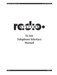
UltraLink90 Wireless Video Set
2.4 GHz Wireless
User’s Manual
UltraLink90 Wireless Video Set
FCC Part 90
PR-97A00002-00
INTRODUCTION
Congratulations, and thank you for purchasing the UltraLink90 Outdoor
Video Wireless Set. This totally contained surveillance system is designed
and manufactured using stringent standards and customer input. Features
Include:
• FCC-approved 2.4 GHz transmitter and receiver
• A/C or D/C operation
• Readily accepts color or B/W, NTSC or PAL
• Easy installation
• User-friendly operation
As you read through this manual, please keep in mind your system has
been rigorously inspected for utmost quality assurance prior to shipment.
About the UltraLink90
The UltraLink90 Outdoor Video Transmitter incorporates a FCCapproved transmitter with a high-impact protective NEMA4-rated
housing. The result is an extremely powerful surveillance and
monitoring tool. Designed for weather exposed environments, the
UltraLink90 is capable of transmitting quality video footage up to
15 miles line of sight depending on the surrounding environment.
Whether you are gathering evidence, monitoring industrial processes,
or viewing inaccesible areas, the UltraLink90 Outdoor Video
Wireless Set will provide you with an effective wireless solution.
NOTE: In accordance with United States Codes, this unit is not equipped with audio capabilities. It
is illegal for non-authorized persons to own, possess, or utilize surreptitious listening devices for the
purpose of intercepting and/or recording another person.s oral communications.Any modi cations made
to this unit are unauthorized and will immediately void the Manufacturer.s Warranty.
Part 90 High Power:
THIS EQUIPMENT MAY ONLY BE OPERATED UNDER A PART 90 LICENSE
ISSUED BY THE FCC. THE USER IS RESPONSIBLE FOR OPERATING THIS
EQUIPMENT IN COMPLIANCE WITH FCC RULES. OPERATION OF THIS
EQUIPMENT WITHOUT A VALID FCC LICENSE COULD RESULT IN THE ISSUANCE
OF FINES TO THE USER OR SEIZURE OF THE EQUIPMENT.
FCC ID Number NH5FWVTXBD12A
i
Table of Contents
General......................................................1
Pre-Operation ...........................................1
Deployment of Transmitter ........................1
Deployment of Receiver ............................2
Using a Monitor/Recorder .........................2
Safety Precautions ....................................3
Warranty Information ............................. 3-4
ii
General
The transmitting antenna, also known as a “directional antenna”,
is located under the unit’s top cover (4 x 4 NEMA4 case). The 2.4
GHz antenna on the receiver is located under the unit’s top cover
(6 x 6 NEMA4 case) and faces toward the front of the unit. For
optimal performance, the transmitting antenna should be oriented
with the receiving antenna. Although the unit will still work properly
without the units facing each other, the transmission range may be
decreased and/or degrated.
Pre-Operation
1. Read this manual thoroughly!
2. Decide on a video source for video input into the transmitter.
Connect the CLR video camera to the appropriate connector
(only one connector will t the unit).
Deployment of the UltraLink90 Transmitter
1. Determine the placement of your transmitting unit and mount
to a stable surface using standard hardware (not provided).
2. Use the cable provided to connect the video output from the
video source to the video input on the transmitter.
3. Run the provided D/C wiring harness to the provided 12V DC
source.
4. Plug the power supply (provided) into the nearest 110~115
Volt A/C outlet and use the 2.1mm connector to connect to the
wiring harness.
5. If you choose to use your own power supply, make certain it is
a regulated power supply rated at 12V DC@500ma.
1
Deployment of the UltraLink90 Video Receiver
1. Determine the placement of your receiving unit and mount to a
stable surface using standard hardware (not provided).
2. Remove the four screws from the face of the receiver (marked RX
-- larger of the two units) and set aside the lid.
3. Use the cable provided to connect to the display.
4. Use the combined video and DC power cable to connect to the
video jack and the DC power source.
5. Plug the included power supply into the nearest 110~115 Volt
A/C outlet and use the 2.1mm connector to connect to the wiring
harness--power splitter may be required.
6. If you choose to use your own power supply, make certain it is
a regulated power supply rated at 12V DC@500ma. This also
applies to 12V batteries (12V batteries operate at 13.5V DC
typically).
7. With power applied to the receiver, check the LED indicator for
proper receiver channel selection. This should match the number
on the transmitter (units will not function unless the channels are
the same on both the transmitter and receiver). Use push button
to toggle the right channel number (if needed).
8. Replace the lid on the receiver and secure using the four screws:
don’t over tighten to avoid splitting the lid.
9. With cable provided, connect the CLR video camera to the
transmitter (smaller of the two units) and connect power supply.
Using a Monitor or Recorder
If you wish only to view your video using a standard monitor or
television, you will need to connect your receiver directly to your
monitor as follows (check with user manual provided with your unit):
1. Connect the provided cable from the receiver to the video input
jack on your monitor using a standard RCA connector.
2. Change the video input for your monitor accordingly.
3. Your monitor should display the view from your camera. Make any
necessary adjustments to your transmitter and receiver for best
reception.
2
Important Safety Precautions
Warranty Information
The manufacturer warrants their products to be free from defects in
material or workmanship for a period of ninety (90) days from the
date of original purchase. Exceptions on selected products are as
follows:
Product Warranty Coverage Consumer products 1 year. If a product
must be returned for repair, it should be returned either in its original
carton or similar packaging affording an equal degree of protection.
All freight costs associated with replacement or repair of products are
the responsibility of the Purchaser. The Manufacturer is not obligated
to provide the Purchaser with a substitute unit during the warranty
period or at any time thereafter.
3
The limited warranty stated herein is subject to all of the following terms and conditions.
TERMS AND CONDITIONS
1. NOTIFICATION OF CLAIMS: WARRANTY SERVICE: If Purchaser believes that the product is
defective in material or workmanship, then written notice with an explanation of the claim shall be
given promptly by Purchaser to the Manufacturer but all claims for warranty service must be made
within the warranty period. No repair or replacement of any product or part thereof shall extend
the warranty period as to the entire product. The speci c warranty on the repaired part only shall
be in effect for a period of ninety (90) days following the repair or replacement of that part or the
remaining period of the product parts warranty, whichever is greater.
2. EXCLUSIVE REMEDY: ACCEPTANCE: Purchaser’s exclusive remedy and the anufacture’s sole
obligation is to supply all labor necessary to repair any product found to be defective within the
warranty period. Purchaser’s failure to make a claim as provided in paragraph 1 above or continued
use of the product shall constitute an unquali ed acceptance of such product and a waiver by
Purchaser of all claims thereto.
3. EXCEPTIONS TO LIMITED WARRANTY: The Manufacturer shall have no liability or obligation
to Purchaser with respect to any product requiring service during the warranty period which is
subjected to any of the following: abuse, improper use, negligence, accident, modi cation, failure
of the end-user to follow the operating procedures outlined in the user.s manual, failure of the enduser to follow the maintenance procedures in the service manual for the product, attempted repair
by non-quali ed personnel, operation of the product outside of the published environmental and
electrical parameters, or if security seal has been defaced, altered, or removed. The Manufacturer
also excludes from warranty coverage products located outside the United States, and consumable
items such as fuses and batteries. Items not manufactured by EEOS, Inc. but included in system
bought by Purchaser are limited to original manufacturer’s warranty and will be repaired by EEOS,
Inc. on cost of material basis.
4. PROOF OF PURCHASE: The purchaser.s dated invoice must be retained as evidence of the
date of purchase and to establish warranty eligibility.
DISCLAIMER OF WARRANTY
EXCEPT FOR THE FOREGOING WARRANTIES, THE MANUFACTURER HEREBY DISCLAIMS
AND EXCLUDES ALL OTHER WARRANTIES, EXPRESS OR IMPLIED, INCLUDING, BUT
NOT LIMITED TO ANY AND/OR ALL IMPLIED WARRANTIES OF MERCHANTABILITY,
FITNESS FOR A PARTICULAR PURPOSE AND/OR ANY WARRANTY WITH REGARD TO
ANY CLAIM OF INFRINGEMENT THAT MAY BE PROVIDED IN SECTION 2-312(3) OF THE
UNIFORM COMMERCIAL CODE AND/OR ANY OTHER COMPARABLE STATE STATUE. THE
MANUFACTURER HEREBY DISCLAIMS ANY REPRESENTATIONS OR WARRANTY THAT
THE PRODUCT IS COMPATIBLE WITH ANY COMBINATION OF NON-MANUFACTURER.S
PRODUCTS PURCHASER MAY CHOOSE TO CONNECT TO THE
PRODUCT.
LIMITATION OF LIABILITY
THE LIABILITY OF THE MANUFACTURER, IF ANY, AND PURCHASER.S SOLE AND EXCLUSIVE
REMEDY FOR DAMAGES FOR ANY CLAIM OF ANY KIND WHATSOEVER, REGARDLESS OF
THE LEGAL THEORY AND WHETHER ARISING IN TORT OR CONTRACT, SHALL NOT BE
GREATER THAN THE ACTUAL PURCHASE PRICE OF THE PRODUCT WITH RESPECT TO
WHICH SUCH CLAIM IS MADE. IN NO EVENT SHALL THE MANUFACTURER BE LIABLE TO
PURCHASER FOR ANY SPECIAL, INDIRECT, INCIDENTAL, OR CONSEQUENTIAL DAMAGES
OF ANY KIND INCLUDING, BUT NOT LIMITED TO, COMPENSATION, REIMBURSEMENT OR
DAMAGES ON ACCOUNT OF THE LOSS OF PRESENT OR PROSPECTIVE PROFITS OR FOR
ANY OTHER REASON WHATSOEVER.
Manufactured for EEOS by Backgrounds Unlimited, Inc. in conjuction with First Witness Video Surveillance Systems
4
Electrical Equipment & Optical Systems
3575 South West Temple, Suite 5
Salt Lake City, Utah 84115
(801) 261-2881
www.eeosinc.com
[email protected]