1
TiX640, TiX660, TiX1000
Thermal Imager
PN 4583397
September 2014
© 2014 Fluke Corporation. All rights reserved. Specifications are subject to change without notice.
All product names are trademarks of their respective companies.
LIMITED WARRANTY AND LIMITATION OF LIABILITY
This Fluke product will be free from defects in material and workmanship for two years from the date of purchase. This
warranty does not cover fuses, disposable batteries, or damage from accident, neglect, misuse, alteration, contamination, or
abnormal conditions of operation or handling. Resellers are not authorized to extend any other warranty on Fluke’s behalf.
To obtain service during the warranty period, contact your nearest Fluke authorized service center to obtain return
authorization information, then send the product to that Service Center with a description of the problem.
THIS WARRANTY IS YOUR ONLY REMEDY. NO OTHER WARRANTIES, SUCH AS FITNESS FOR A PARTICULAR
PURPOSE, ARE EXPRESSED OR IMPLIED. FLUKE IS NOT LIABLE FOR ANY SPECIAL, INDIRECT, INCIDENTAL OR
CONSEQUENTIAL DAMAGES OR LOSSES, ARISING FROM ANY CAUSE OR THEORY. Since some states or countries
do not allow the exclusion or limitation of an implied warranty or of incidental or consequential damages, this limitation of
liability may not apply to you.
Fluke Corporation
P.O. Box 9090
Everett, WA 98206-9090
U.S.A.
11/99
Fluke Europe B.V.
P.O. Box 1186
5602 BD Eindhoven
The Netherlands
Table of Contents
Chapter
1
Title
Page
Before You Start ...........................................................................................................
Introduction ....................................................................................................................
How to Contact Fluke .....................................................................................................
Safety Information ..........................................................................................................
Optional Accessories......................................................................................................
Technical Description .....................................................................................................
Functional Principle ...................................................................................................
Description of the Functional Units ............................................................................
Lens ......................................................................................................................
Detector ................................................................................................................
Detector Electronics..............................................................................................
Image Processing Electronics...............................................................................
Optomechanics .....................................................................................................
Controls ................................................................................................................
Power Supply........................................................................................................
Interfaces ..............................................................................................................
Technical Data...........................................................................................................
Unpacking and Control ...................................................................................................
i
1-1
1-3
1-4
1-4
1-8
1-8
1-8
1-8
1-8
1-10
1-10
1-10
1-11
1-11
1-11
1-12
1-12
1-14
TiX640, TiX660, TiX1000
Users Manual
2
Parts of the Thermal Imager ..........................................................................................
Quick Guide ...................................................................................................................
Preparation ...............................................................................................................
Start ..........................................................................................................................
Display ......................................................................................................................
Setting the Focus ......................................................................................................
Setting the Temperature Range ................................................................................
Saving Images ..........................................................................................................
Saving with "Check" .............................................................................................
Quick Saving ........................................................................................................
Menu Functions ........................................................................................................
Shut-Down ................................................................................................................
Data Transmission to the Computer ..............................................................................
Start-Up .........................................................................................................................
Hand Strap ................................................................................................................
Tripod ........................................................................................................................
Power Supply ............................................................................................................
Memory Card ............................................................................................................
Lens Replacement ....................................................................................................
Operation using the Gigabit Ethernet (GigE) Interface..............................................
Ethernet Cable and AC Adapter ...........................................................................
AC Adapter Connection .......................................................................................
Operation with Breakout Box ....................................................................................
Trigger Function ........................................................................................................
SyncOut ....................................................................................................................
1-15
1-17
1-18
1-18
1-19
1-20
1-20
1-23
1-23
1-23
1-24
1-24
1-25
1-25
1-25
1-25
1-25
1-25
1-26
1-26
1-27
1-27
1-27
1-29
1-29
Elements of the User Interface ...................................................................................
Introduction ....................................................................................................................
Button Functions ............................................................................................................
Image Elements .............................................................................................................
2-1
2-3
2-5
2-7
ii
Contents (continued)
3
Setting the Temperature Scale .......................................................................................
Focus .............................................................................................................................
LaserSharp® Auto Focus ...........................................................................................
Permanent LaserSharp® Auto Focus.........................................................................
EverSharp Multifocal Recording ................................................................................
Spot Editor .....................................................................................................................
Saving ............................................................................................................................
Saving with Check ..........................................................................................................
Quick Saving ..................................................................................................................
2-9
2-10
2-10
2-10
2-10
2-11
2-11
2-12
2-12
Display Menus ..............................................................................................................
Introduction ....................................................................................................................
Image Submenu .............................................................................................................
Manual Submenu ......................................................................................................
Mode Submenu .........................................................................................................
Zoom Submenu .........................................................................................................
Palette Submenu .......................................................................................................
Elements Submenu ...................................................................................................
Isotherms Submenu ..................................................................................................
Filter Mode Submenu ................................................................................................
Format (Subwindowing) Submenu ............................................................................
File Menu .......................................................................................................................
Directory Structure.....................................................................................................
Load Submenu ..........................................................................................................
Save Submenu ..........................................................................................................
IR Photonotes Submenu ...........................................................................................
Format SD Submenu .................................................................................................
Saving Format Submenu ...........................................................................................
Measure Menu ...............................................................................................................
Spot Temperature Submenu .....................................................................................
3-1
3-3
3-4
3-5
3-7
3-10
3-11
3-14
3-15
3-17
3-17
3-18
3-18
3-18
3-21
3-24
3-25
3-25
3-27
3-27
iii
TiX640, TiX660, TiX1000
Users Manual
4
Measurement Definitions Submenu ..........................................................................
Correction Submenu .................................................................................................
GPS Submenu ..........................................................................................................
Laser Submenu.........................................................................................................
Settings Menu ................................................................................................................
Calibration Submenu ................................................................................................
Extras Submenu .......................................................................................................
Automatic Submenu..................................................................................................
Compensation Submenu ..........................................................................................
Buttons Submenu .....................................................................................................
Digital Alarm Output Submenu..................................................................................
Configuration Submenu ............................................................................................
System Menu .................................................................................................................
Display Submenu ......................................................................................................
Regional Submenu ...................................................................................................
Date and Time Submenu ..........................................................................................
Menu Layout Submenu .............................................................................................
Menu Control Submenu ............................................................................................
Info Submenu............................................................................................................
3-28
3-32
3-36
3-36
3-37
3-37
3-38
3-39
3-40
3-41
3-44
3-45
3-47
3-48
3-49
3-49
3-50
3-51
3-52
Maintenance .................................................................................................................
Introduction ....................................................................................................................
How to Clean .................................................................................................................
Calibration .....................................................................................................................
Environmental ................................................................................................................
Service...........................................................................................................................
Battery ...........................................................................................................................
4-1
4-3
4-3
4-3
4-3
4-4
4-4
iv
List of Tables
Table
1-1.
1-2.
1-3.
1-4.
1-5.
1-6.
1-7.
2-1.
2-2.
2-3.
3-1.
3-2.
3-3.
Title
Page
Symbols.................................................................................................................................
Thermography System with 1024 x 768 IR Pixel Resolution .................................................
Thermal Imager Components ................................................................................................
Front View of Thermal Imager ...............................................................................................
Control Locations ..................................................................................................................
Arrangement of the Image Elements .....................................................................................
Breakout Box .........................................................................................................................
Control Locations ..................................................................................................................
Shortcuts ...............................................................................................................................
Image Elements ....................................................................................................................
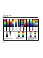
Palettes .................................................................................................................................
Setting Selections ..................................................................................................................
Button Functions ...................................................................................................................
v
1-7
1-9
1-15
1-16
1-17
1-19
1-28
2-4
2-5
2-7
3-12
3-26
3-42
TiX640, TiX660, TiX1000
Users Manual
vi
List of Figures
Figure
Title
Page
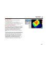
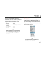
1-1. Lens Cover Laser Warning .................................................................................................... 1-5
1-2. Ethernet Cable and AC Adapter ............................................................................................ 1-27
1-3. AC Adapter ............................................................................................................................ 1-27
vii
TiX640, TiX660, TiX1000
Users Manual
viii
Chapter 1
Before You Start
Title
Page
Introduction .............................................................................................................. 1-3
How to Contact Fluke ............................................................................................... 1-4
Safety Information .................................................................................................... 1-4
Optional Accessories................................................................................................ 1-8
Technical Description ............................................................................................... 1-8
Functional Principle ........................................................................................... 1-8
Description of the Functional Units.................................................................... 1-8
Lens ............................................................................................................ 1-8
Detector ......................................................................................................1-10
Detector Electronics ...................................................................................1-10
Image Processing Electronics ....................................................................1-10
Optomechanics ..........................................................................................1-11
Controls ......................................................................................................1-11
Power Supply .............................................................................................1-11
Interfaces....................................................................................................1-12
Technical Data .................................................................................................1-12
1-1
TiX640, TiX660, TiX1000
Users Manual
Unpacking and Control ........................................................................................... 1-14
Parts of the Thermal Imager ................................................................................... 1-15
Quick Guide ............................................................................................................ 1-17
Preparation ...................................................................................................... 1-18
Start ................................................................................................................. 1-18
Display ............................................................................................................. 1-19
Setting the Focus............................................................................................. 1-20
Setting the Temperature Range ...................................................................... 1-20
Saving Images ................................................................................................. 1-23
Saving with "Check" ................................................................................... 1-23
Quick Saving.............................................................................................. 1-23
Menu Functions ............................................................................................... 1-24
Shut-Down ....................................................................................................... 1-24
Data Transmission to the Computer ....................................................................... 1-25
Start-Up .................................................................................................................. 1-25
Hand Strap ...................................................................................................... 1-25
Tripod .............................................................................................................. 1-25
Power Supply .................................................................................................. 1-25
Memory Card ................................................................................................... 1-25
Lens Replacement........................................................................................... 1-26
Operation using the Gigabit Ethernet (GigE) Interface .................................... 1-26
Ethernet Cable and AC Adapter ................................................................ 1-27
AC Adapter Connection ............................................................................. 1-27
Operation with Breakout Box ........................................................................... 1-27
Trigger Function .............................................................................................. 1-29
SyncOut ........................................................................................................... 1-29
1-2
Before You Start
Introduction
Introduction
The TiX640, TiX660, and TiX1000 Thermal Imagers (the
Product) are state-of-the-art thermography systems for
precise, quick, and non-contact measurement of the
surface temperature of objects.
These thermal imagers are designed for universal
application and can be used both as a mobile and as a
stationary device for measuring and storing temperature
values. The compact and resilient design and a high
degree of protection allow for industrial application even
in unfavorable external conditions. The low weight of the
device, as well as the long operating time of the
rechargeable battery allow for efficient use in this.
High measurement accuracy, precision optics with
extraordinary image quality, as well as the universal
interface concept for digital real-time thermography data
collection using GigE-Vision allow for using the thermal
imager in a wide variety of applications.
1
Diverse accessories and different software packages for
pre- and post-processing of the recordings turn the
product into a universal thermography system for a broad
range of applications.
Typical fields of application of the thermography system
are:
•
thermographic inspection of electrical and
mechanical systems
•
optimization of components and assemblies
•
material inspections
•
control of process temperatures
•
quality assurance
•
building inspection and diagnostics
•
research and development
The thermal imager is equipped with a digital color video
camera in order to document the measuring situation on
photos. Infrared (IR) and visual light images, as well as
image sequences can be saved to SD and SDHC
(Secure Digital High Capacity) cards. For the purposes of
visualization, the thermography system is equipped with a
swivel-mounted color thin film transistor (TFT) viewfinder
and a pivot and swivel-mounted active color TFT display.
1-3
TiX640, TiX660, TiX1000
Users Manual
How to Contact Fluke
Safety Information
To contact Fluke, call one of the following telephone
numbers:
A Warning identifies conditions and procedures that are
dangerous to the user. A Caution identifies conditions
and procedures that can cause damage to the Product or
the equipment under test.
Technical Support USA: 1-800-44-FLUKE
(1-800-443-5853)
•
Calibration/Repair USA: 1-888-99-FLUKE
(1-888-993-5853)
•
Canada: 1-800-36-FLUKE (1-800-363-5853)
•
Europe: +31 402-675-200
•
Japan: +81-3-6714-3114
•
Singapore: +65-6799-5566
•
Anywhere in the world: +1-425-446-5500
Go to www.fluke.com to register your product, download
manuals, and find more information.
•
To view, print, or download the latest manual supplement,
visit http://us.fluke.com/usen/support/manuals.
1-4
Warning
To prevent eye damage and personal injury:
•
Do not look into the laser. Do not point
laser directly at persons or animals or
indirectly off reflective surfaces.
•
Do not open the Product. The laser beam
is dangerous to eyes. Have the Product
repaired only through an approved
technical site.
•
Do not locate the laser beam so that it is
at eye level when you install the
thermography system.
Before You Start
Safety Information
•
The Product is equipped with an LED
light to illuminate the image. Avoid any
direct eye contact and do not point the
LED light at people, animals, or reflective
surfaces.
Additional laser warning information is on the case of the
Product, see Figure 1.
•
Do not use the Product around explosive
gas, vapor, or in damp or wet
environments.
•
Use this Product indoors only.
•
Examine the case before you use the
Product. Look for cracks or missing
plastic. Carefully look at the insulation
around the terminals.
•
Do not use the Product if it is damaged.
•
Do not use the Product if it operates
incorrectly.
1
hvh300.eps
Figure 1-1. Lens Cover Laser Warning
Warning
To prevent possible electrical shock, fire, or
personal injury:
•
Carefully read all instructions.
•
Read all safety information before you
use the Product.
•
Use the Product only as specified or the
protection supplied by the Product can
be compromised.
1-5
TiX640, TiX660, TiX1000
Users Manual
•
Replace the batteries when the low
battery indicator shows to prevent
incorrect measurements.
•
Do not keep cells or batteries in a
container where the terminals can be
shorted.
•
Remove the batteries if the Product is
not used for an extended period of time,
or if stored in temperatures above 50 °C.
If the batteries are not removed, battery
leakage can damage the Product.
•
Do not put battery cells and battery
packs near heat or fire. Do not put in
sunlight.
•
1-6
Batteries contain hazardous chemicals
that can cause burns or explode. If
exposure to chemicals occurs, clean
with water and get medical aid.
•
Do not disassemble the battery.
•
Do not short the battery terminals
together.
•
Do not disassemble or crush battery
cells and battery packs.
Warning
For safe operation and maintenance of the
Product:
•
Repair the Product before use if the
battery leaks.
•
Be sure that the battery polarity is
correct to prevent battery leakage.
•
Use only Fluke approved power adapters
to charge the battery.
1
Before You Start
Safety Information
Table 1-1 is a list of symbols used on the Imager and in
this manual.
Table 1-1. Symbols
Symbol
Description
Symbol
Description
Important information. See manual.
On/Off Symbol.
Battery status.
Conforms to relevant South Korean EMC
standards.
Battery charging when animated.
Conforms to relevant Australian standards.
Conforms to relevant North American Safety
Standards.
Conforms to requirements of European Union and European Free Trade Association.
This Product contains a lithium-ion battery. Do not mix with the solid waste stream. Spent batteries should be
disposed of by a qualified recycler or hazardous materials handler per local regulations. Contact your
authorized Fluke Service Center for recycling information.
This product complies with the WEEE Directive (2002/96/EC) marking requirements. The affixed label
indicates that you must not discard this electrical/electronic product in domestic household waste. Product
Category: With reference to the equipment types in the WEEE Directive Annex I, this product is classed as
category 9 “Monitoring and Control Instrumentation” product. Do not dispose of this product as unsorted
municipal waste. Go to Fluke's website for recycling information.
Warning. Laser.
1-7
TiX640, TiX660, TiX1000
Users Manual
Optional Accessories
Technical Description
•
ac adapter with 14-pin LEMO connector
Functional Principle
•
replacement lenses, macro attachments
•
protective window for lenses, laser protection filter
The Product is a thermography system designed for the
long-wave infrared spectral range (LWIR) of 7.5 µm to
14 µm. The lens reproduces the object scene to a
microbolometer array with 1024 x 768 and/or 640 x 480
pixels. The electrical signal of the detector array is
processed further by the internal electronics. In this, the
electronics comprise all functions required for camera
operation, such as actuation of the microbolometer array,
A/D conversion, offset and gain correction, pixel correction,
as well as actuation of the different interfaces.
•
breakout box
•
Bluetooth headset
•
gigabit Ethernet card
•
Ethernet cable with 8-pin LEMO connector
•
device tripod
Operation is optionally performed directly using the
integrated keyboard (joystick, focus rocker switch, function
buttons) or using optional interfaces. RS232, Ethernet (GigE
Vision), or USB2.0 are available as interfaces. Specific
software packages are required in order to use these
interfaces.
Description of the Functional Units
Lens
The camera lens collects the IR radiation in the field of
view emitted by the measuring object and reproduces this
IR radiation on the detector array. Field of view (FOV)
and resolution/measuring spot size (IFOV, Instantaneous
Field of View) are determined at the same distance to the
focal distance f of the used lens.
1-8
1
Before You Start
Technical Description
Table 1-2 is a list the optional lenses that are available:
Table 1-2. Thermography System Lenses
1024 x 768
Focal
Model
Lens
distance
Focus (m)
(mm)
IFOV
FOV (°)
(mrad)
640 x 480
IFOV (mrad)
FOV (°)
FLK-Xlens/Sup-Wide
Super wide-angle lens
7.5
0.17
2.3
135.8 x 104.4
3.3
128.9 x 92.7
FLK-Xlens/Wide
Wide-angle lens
15
0.47
1.1
68.7 x 50.7
1.7
62.3 x 46.4
FLK-Xlens/Stan
Standard lens
30 0.72
0.6
32.4 x 24.7
0.8
30.9 x 23.1
FLK-Xlens/Tele
Telephoto lens
60
1.99
0.3
16.4 x 12.4
0.4
14.9 x 11.3
FLK-Xlen/SupTele
Super telephoto lens
120
6.58
0.1
8.1 x 6.2
0.2
7.5 x 5.7
Focal
Model
Lens
distance
Focus (m)
(mm)
IFOV
Resolution
(mrad)
(μm)
IFOV (mrad)
Resolution
(μm)
FLK-Xlens/Macro1
Close-up 0.2x
for 30
137.4
85.5 x 63.2
81
78.1 x 57.9
119
FLK-Xlens/Macro2
Close-up 0.5x
for 30
47.4
34.3 x 25.3
32
31.3 x 23.2
47
FLK-Xlens/Macro3
Close-up 0.5x
for 60
100
35.1 x 26.5
35
32.3 x 24.4
50
1-9
TiX640, TiX660, TiX1000
Users Manual
Detector
The thermal imager is equipped with an uncooled
microbolometer FPA detector (uncooled Focal Plane
Array) with a resolution of (1024 x 768) or (640 x 480) IR
pixels. The individual elements of the detector are
microscopically small thin-film resistors on extremely thin
diaphragms arranged a few micrometers above the
silicon read-out circuit in an unsupported manner. The
lens of the thermography system reproduces the thermal
radiation from the scene onto these detector elements
and these detector elements absorb this radiation. The
temperature change of the detector elements results in
signals that can be analyzed electronically, read-out lineby-line and column-by-column using a read-out circuit.
Use of an uncooled detector ensures the quick availability
of the camera function at start-up (starting time <30
seconds) and a long mean time to failure (MTTF) in
continuous operation.
Detector Electronics
Detector electronics supply the BIAS voltages and further
actuation signals required for detector operation to ensure
that the analog output signal of the detector is
preprocessed and digitalized.
1-10
Image Processing Electronics
With the help of an FPGA (Field Programmable Gate
Array) and up to two processors, real-time image
processing with the following essential functions
(depending on the equipment) is implemented:
•
detector electronics interface
•
gain and offset correction
•
defect pixel treatment
•
low-pass filtration
•
zoom generator
•
graphics overlay
•
VIS/IR/graphics mixer
•
GigE-Vision interface
•
PC interfaces (Wi-Fi SD Card/USB2.0)
•
video image interfaces (DVI-D, FBAS)
1
Before You Start
Technical Description
Optomechanics
With the help of an optomechanic assembly, the following
functions are implemented:
•
LaserSharp® Auto Focus
•
measuring range switch-over (apertures)
•
internal NUC (Non Uniformity Correction) with shutter
Furthermore, this assembly optionally comprises a
module for hardware-based increase of the geometric
resolution of the thermography system to 2048 x 1536 IR
pixels (detector with 1024 x 768 pixels) and
1280 x 960 IR pixels (detector with 640 x 480 pixels) in
SuperResolution mode.
Controls
The thermal imager is controlled by means of a focus
rocker switch with center function for autofocus, the
function buttons Automatic, Temperature,
Start/Stop/Save, and the multi-function buttons and
at the right top. On the backside of the camera, a power
button for right-thumb operation, a joystick with
center function (Enter), and the button (Cancel) can be
found. The controls of the thermal imager are arranged
for single-hand operation with the right hand. Another
multi-function button can be found at the top of the
handle. When carrying the camera on its handle, it can be
operated using the thumb of your right hand.
Specific modes of camera operation and presettings can
be configured using menus. Chapter 2 contains a detailed
description of how to operate the thermography system,
as well as a detailed description of the menu structure.
The thermal imager can be controlled remotely via the
RS232 or GigE-Vision interfaces.
Power Supply
Optionally, an external 15 V ac adapter (accessories) or a
rechargeable lithium-ion battery 7.2 V (accessories) can
be used to supply the thermal imager with power.
The ac adapter is connected to the 14-pin (right-hand
side) LEMO socket on the backside of the housing. The
rechargeable battery is inserted vertically into the
designated position on the backside of the thermography
system (see Chapter 3).
1-11
TiX640, TiX660, TiX1000
Users Manual
Interfaces
The thermography system is equipped with the following
interfaces:
•
drive for SD/SDHC card (behind the cover on the left
side of the camera, unfold the display)
•
DVI-D (HDMI socket) behind the cover on the
backside of the camera, composite video (LEMO
14-pin)
•
2 x digital E/A for external trigger input/trigger output
(TTL level, LEMO 14-pin)
•
2 x analog output 0-5V (LEMO 14-pin)
•
USB 2.0 (mini-AB, behind the cover on the backside
of the camera)
•
RS232 (LEMO 14-pin)
•
GigE-Vision (LEMO 8-pin)
Simultaneously using several interfaces on the 14-pin
LEMO socket is allowed for by means of a breakout box.
The breakout box is also used for external power supply.
As an alternative to the digital high-resolution DVI-D
image data on the HDMI socket, the analog image data
(4:3 PAL/NTSC) is available as FBAS signal (composite)
on the 14-pin LEMO socket. The HDMI socket can be
used to connect screens processing a resolution of
1280 x 768 or 1280 x 800 in accordance with the VESA
standard.
1-12
In connection with the provided software, the GigE-Vision
interface allows for remotely controlling the thermography
system, as well as for transmitting digital image
information to a PC in real time.
Note
SmartView software support for GigE-Vision is
planned in 2015.
®
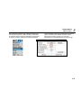
Technical Data
Spectral range ................................ 7.5 µm to 14 µm
Temperature measurement range
TiX1000, TiX660 ......................... -40 °C to +1200 °C
(-40 °F to +2192 °F)
with high temperature option:
up to 2000 °C (3632 °F)
TiX640 ........................................ -40 °C to +1200 °C
(-40 °F to +2192 °F)
Measurement accuracy .................. ±1.5 K or ±1.5 %
Image resolution (pixels)
TiX1000 ...................................... 1024 x 768
2048 x 1536 (SuperResolution)
TiX660 ........................................ 640 x 480
1280 x 960 (SuperResolution)
TiX640 ........................................ 640 x 480
Frame rate (@ max. image resolution)
TiX1000 ...................................... 30 Hz
TiX660, TiX640 ........................... 60 Hz
Before You Start
Technical Description
Field of view (FOV) standard 30 mm lens
TiX1000 ...................................... 32.4° x 24.7°
TiX660, TiX640 .......................... 30.9° x 23.1°
Thermal sensitivity [NETD]
TiX1000 ...................................... ≤0.05 °C at 30 °C target
temp (50 mK)
TiX660, TiX640 .......................... ≤0.03 °C at 30 °C target
temp (30 mK)
Digital zoom.................................... up to 32x
A/D conversion ............................... 16-bit
Power supply
External ...................................... 12 V dc to 24 V dc
Battery ........................................ Standard lithium-ion video
camera battery
Operating temperature
with external power .................... -25 °C to +55 °C
(-13 °F to +131 °F)
with battery power ...................... -25 °C to +40 °C
(-13 °F to +104 °F)
Storage temperature ...................... -40 °C to +70 °C
(-40 °F to +158 °F)
Operating altitude ........................... <2000 m
Humidity ......................................... relative humidity 10 % to
95 %, non-condensing
Shock ............................................. Operational: 25G, IEC 68-2-29
Vibration ......................................... Operational: 25G, IEC 68-2-6
Protection class .............................. IP54
1
Safety ..............................................meets IEC 60825-1: class 2
Electromagnetic Compatibility .........meets IEC 61326-1: Portable
Applies to use in Korea only. ......Class A Equipment (Industrial
Broadcasting &
[1]
Communication Equipment)
[1] This product meets requirements for industrial (Class A)
electromagnetic wave equipment and the seller or user should
take notice of it. This equipment is intended for use in business
environments and is not to be used in homes.
Dimensions with standard 30 mm lens
TiX1000, TiX660 .........................210 mm x 125 mm x 155 mm
(8.25 in x 4.9 in x 6.1 in)
TiX640 .........................................206 mm x 125 mm x 139 mm
(8.1 in x 4.9 in x 5.5 in)
Weight with standard 30 mm lens
TiX1000, TiX660 .........................1.95 kg (4.3 lb)
TiX640 .........................................1.4 kg (3.1 lb)
Display ............................................Extra-large 5.6 in color TFT
display, 1280 x 800 pixel
resolution, Suitable for
daylight operation
Viewfinder
TiX1000, TiX660 .........................Tilt-able LCoS color
viewfinder display, 800 x 600
pixel resolution
TiX640 .........................................none
Digital visible light camera...............up to 8 Megapixel resolution
for image and video
recording
Image/video storage........................SDHC memory card
1-13
TiX640, TiX660, TiX1000
Users Manual
Interfaces
Supported in camera
data ports (image transfer).......... SD card, USB 2.0, video
output DVI-D HDMI
(GigE vision, RS232
available in 2015)
®
Supported in SmartView
software ...................................... SD card
(USB 2.0, GigE Vision,
RS232 available in 2015)
Features:
•
•
•
•
•
•
•
•
•
•
•
•
•
•
•
Fluke Connect® compatible
AutoBlend™ mode
LaserSharp® Auto Focus (TiX660, TiX1000 only)
Auto Focus
Manual Focus
EverSharp multifocal recording
SuperResolution
Dynamic SuperResolution
Laser pointer
Laser distance meter (TiX660, TiX1000 only)
GPS
Text and voice annotation
Audio
Replaceable Smart Batteries with LED level indicator (2
with TiX660, TiX1000/1 with TiX640)
SmartView® software compatible
1-14
Unpacking and Control
When you receive your thermal imager, check the
components for completeness and integrity. Possible
damages must be reported to the supplier immediately.
The thermal imager system is delivered in a transport
box.
The basic package contains the following components:
•
thermography camera with lens and 5.6" TFT display
•
integrated digital color video camera
•
depending on the equipment, Laser Distance
Meter/laser pointer, GPS
•
rechargeable lithium-ion battery NP-QM91D (Sony)
(2 with TiX660, TiX1000/1 with TiX640)
•
battery charger
•
SDHC card
•
card adapter for SD card
•
protective lens cap
•
shoulder strap
•
users manual (go to www.fluke.com to download the
users manual for this Product)
•
safety information
•
transport box/transport packaging
•
ac adapter
Before You Start
Parts of the Thermal Imager
1
Parts of the Thermal Imager
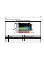
See Table 1-3 and Table 1-4 for a general overview of the
thermal imager components.
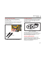
Table 1-3. Thermal Imager Components
2
3
4
1
5
40
TiX6
MAL
THER
GER
IMA
6
7
9
10
8
hvh013.eps
Item
Description
Item
Description
WLAN/Bluetooth
Connection for GigE-Vision, RS232
Multifunction button
Connection for power supply, trigger, FBAS
Handle
SD card slot
Color TFT viewfinder
USB port
Lithium-ion battery
DVI port
1-15
TiX640, TiX660, TiX1000
Users Manual
Table 1-4. Front View of Thermal Imager
Item
Description
3
4
1
5
Color Video Camera
Lens
Laser Range Finder
LED Video Light
Color TFT Display
2
TiX640
THERMAL
IMAGER
hvh014.eps
1-16
Before You Start
Quick Guide
1
Quick Guide
Table 1-5 shows the location of the controls on your
thermal imager. In order to achieve professional results,
we recommend thoroughly reading the entire manual.
Table 1-5. Control Locations
Item
1
2
3
4
5
10
6
9
8
7
hvh015.eps
Description
Focus rocker switch with autofocus
Temperature
Auto
Multifunction 2
Multifunction 1
Save
Joystick
Power
Escape
Power LED
1-17
TiX640, TiX660, TiX1000
Users Manual
Note
All buttons can be used for multiple functions
triggered either by:
•
half or full pressing: and and/or
Start
To get started:
1.
Provide for power supply by inserting the charged
rechargeable lithium-ion battery or by connecting the
ac adapter to the thermal imager (plug the 14-pin
connector into the right LEMO socket with the red dot
pointing to the top).
2.
Remove the cover of the SD card slot, insert the SD
card into the card slot, and replace the cover.
•
short or long press: , , , and .
The button function can be changed by changing
the settings in menu "Settings" "Buttons".
Preparation
You will need the following equipment:
•
thermal imager
3.
Remove the protective cap from the lens.
•
rechargeable lithium-ion battery or ac adapter with
LEMO connector
4.
•
SmartView® software
•
SD card
•
card reader for SD-/SDHC cards
Push . The imager turns on and the Fluke logo
displays during the boot process. At system
initialization the power-on LED initially flashes green
and then illuminates as steady green to indicate that
the thermal imager is ready-to-operate in Live mode.
1-18
Before You Start
Quick Guide
1
Display
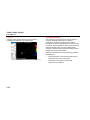
Table 1-6 shows the location of the display elements.
Table 1-6. Arrangement of the Image Elements
2
3
4
1
5
9
6
7
8
hvh022.eps
Item
Description
Item
Description
Camera menu
Rechargeable battery, SDHC card
Temperature unit
Status indications
Date/time
Help line
Camera status (mode)
System information field
Color scale with upper and lower limits
1-19
TiX640, TiX660, TiX1000
Users Manual
Initially, you must select a motif with a contrasting scene
(an active electrical device) and point the thermal imager
towards this scene.
When using the viewfinder, fold the display to the side of
the camera. The viewfinder is switched on by doing so.
You must initially adapt the viewfinder to your eye using
the diopter compensation. For this, the eyecup on the
viewfinder is rotated. In order to find the ideal setting, you
can use the sharpness of the letters initially.
Setting the Focus
Push : middle button for autofocus or to the left or to
the right in order to set the focus for longer or shorter
distances to the measuring object. If the autofocus
function is used, a rectangle will be displayed in the
center of the screen. The distance setting is optimized
taking the distance of the objects contained in the
rectangle.
1-20
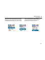
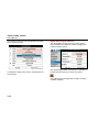
Setting the Temperature Range
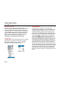
Push the button (shortly). The thermography system
will automatically set a temperature scale of the false
color image corresponding to the current scene:
The required temperature scale can also be set by means
of the joystick . For this, select Menu "Image"
"Manual".
Before You Start
Quick Guide
Depending on the selected input variant, the joystick
can be used in order to set the temperature level and the
temperature range (Level/Range) or the upper and lower
limits (Max/Min) and the values can be input numerically
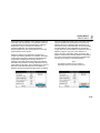
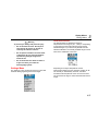
hvh030.jpg
1
as well. In this, the respective joystick and button
functions are displayed to the left of the thermal image.
The respective input dialog for numerical input is
displayed in the center of the field of view:
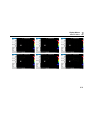
hvh031.jpg
hvh032.jpg
1-21
TiX640, TiX660, TiX1000
Users Manual
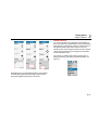
If the options Level/Range and Maximum/Minimum are
set manually, the temperature scale can be adapted
automatically once by shortly pushing the Enter
button. If the Enter button is pushed longer, the scale
is permanently adapted automatically. The AUTO mode
will then be displayed by on the right side of the
image above the color palette. The AUTO mode is
terminated by any manual setting of
Level/Range/Max/Min.
hvh036.jpg
hvh035.jpg
hvh033.jpg
1-22
hvh034.jpg
1
Before You Start
Quick Guide
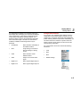
Saving Images
Quick Saving
In order to save the thermal image, the button is
required. The following variants are possible:
Immediately push the button completely image is
Saving with "Check"
1.
2.
Push the button halfway down the life image
will be frozen: .
•
The frozen image can initially be "checked" on
the display or viewfinder.
•
If the image is not to be saved, push the
button: .
, the camera control then
saved immediately:
automatically re-activates the Live mode: .
Note
Deviating from the factory setting described
above, the button can be used to trigger
further functions such as shutter activation,
autofocus, VIS-LED, Laser Distance Meter/laser
pointer before saving the image.
Push the button completely the image is saved.
The process of writing the data is indicated by the
changing color of the map symbol (in the line below the
. When saving, the
image, right-hand side):
camera control automatically activates the Live mode:
.
1-23
TiX640, TiX660, TiX1000
Users Manual
Menu Functions
The thermal imager offers a large number of analysis and
automatic functions and can be configured individually for
the respective use case. The settings and functions are
selected in the camera menu, which is arranged at the
left-hand side of the image area.
Use the joystick (↑, ↓, ←, →) to navigate the menu
and select the functions using the Enter button.
The four main menus can be selected by means of tabs
located on the upper margin of the menu and identified
with the corresponding symbols:
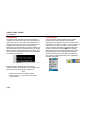
Image Menu
File Menu
Measure Menu
Settings Menu
1-24
Sub-menus can be opened by using the button (Enter)
on the respective menu item, for example, push the
button in order to open the sub-menu for
manually setting the temperature range.
Settings made can be accepted using the buttons Enter
or or discarded using the button.
Shut-Down
Use to open the shut-down dialog, and or
(Enter) to confirm the selection.
Before You Start
Data Transmission to the Computer
Data Transmission to the Computer
SmartView® software will enable the transmission of data
via the optional GigE Vision (available in 2015).
Another data transmission method is to read out the
SDHC card by means of a card reader.
Start-Up
Hand Strap
The thermal imager is designed as highly portable system
for single-hand operation. Initially, adjust the hand strap
attached to the handle piece as required. For this, open
the loop of the hand strap and adjust the length of the belt
strap in such a way that you can comfortably access the
controls with your fingers. Then, close the hook and loop
fastener of the loop.
Tripod
The thermography camera is equipped with a 1/4" photo
thread (DIN 4503) on the bottom of the housing. In order
to achieve rigid camera images, particularly for the
SuperResolution mode, it is recommendable to fix the
thermal imager to a tripod.
1
Power Supply
When using a rechargeable battery, the battery must be
placed on the adapter plate. Push down the rechargeable
battery until it engages. In this, the rechargeable battery
must be pushed slightly to the front towards the lens. In
order to use the thermal imager, please only use the
®
genuine SONY rechargeable batteries NP-QM91D.
The ac adapter is connected to the 14-pin socket on the
right-hand side of the backside of the thermography
system.
Memory Card
The SD card slot is located on the left-hand side of the
camera. In order to guarantee the degree of protection
IP54, the slot is protected by a cover. Pull off the cover to
insert a memory card and insert the SD card into the card
slot. Please observe the proper orientation of the card (▲
to the top). Afterwards, the cover must be re-closed. This
is the only way to ensure the complete degree of
protection of the device.
Caution
Observe the maximum penetration depth of
the photo thread of 4.5 mm (DIN 4503).
1-25
TiX640, TiX660, TiX1000
Users Manual
Lens Replacement
Only replace the lenses in dry and low-dust conditions.
When the lens is removed, the degree of protection IP 54
of the system is no longer guaranteed!
Position the thermal imager on a solid, level underground
so that the lens is directed towards you. Rotate the lens
on the thermography system counterclockwise as far as it
will go and/or until the two red dots are aligned. Then,
remove the lens to the front.
In order to attach the lens, the red marking spots on lens
and camera must be aligned. In this position, the lens
must be pressed slightly against the camera corpus and
turned clockwise until the red dot of the lens is aligned
with the white dot of the camera.
1-26
Operation using the Gigabit Ethernet (GigE)
Interface
Please proceed as follows in order to connect the thermal
imager to a PC/notebook. The accessories described are
contained in the scope of delivery as an option.
•
The Ethernet cable is used in order to establish a
connection to the Ethernet interface of the PC (RJ45
connector).
•
The 8-pin LEMO connector (blue mark) is connected
to the left 8-pin LEMO socket (Figure 1-2, blue mark)
on the camera.
Caution
Make sure you establish the connection to
the correct LEMO socket. Plug the LEMO
connector into the socket with the red dot
directed to the top. Do not force the
connector in.
Before You Start
Start-Up
1
Ethernet Cable and AC Adapter
AC Adapter Connection
The Ethernet cable is used in order to connect the
thermography camera to the 8-pin LEMO socket (lefthand side, blue mark).
To operate while permanently connected to a notebook or
PC, the power should be supplied using the ac adapter
(see Figure 1-3) with the 14-pin LEMO connector on
right-hand side socket.
The 14-pin connector of the ac adapter is plugged into the
right-hand side LEMO socket with the red mark pointing
to the top. See Figure 1-2.
hvh058.eps
Figure 1-3. AC Adapter
When the ac adapter is connected, the camera is
automatically supplied by the ac adapter and no longer by
the rechargeable battery. However, the rechargeable
battery is not charged at the same time.
Ethernet
AC Adapter
Operation with Breakout Box
hvh057.eps
Figure 1-2. Ethernet Cable and AC Adapter
Using the breakout box will expand the connection
options of the thermal imager, see Table 1-7. The
interfaces 2 x analog output, 2 x trigger E/A, PAL/NTSCFBAS, as well as the digital RS232 interface are
accessible via the breakout box.
1-27
TiX640, TiX660, TiX1000
Users Manual
Caution
2.
Connect the breakout box to the COM interface of
the host computer with a commercially available
cable.
3.
Connect the supplied ac adapter to the breakout box.
4.
Push the Power button on the backside of the
camera to turn on the thermography system.
Follow the specified steps on how to
establish the required connections.
1.
Connect the thermography camera to the breakout
box. For this, the 14-pin connecting cable of the
breakout box must be used. It is connected to the
right-hand side 14-pin LEMO socket on the backside
of the thermal imager.
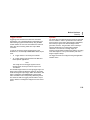
Table 1-7. Breakout Box
3
2
Item
Description
Connecting cable for thermal imager
14-pin LEMO socket for ac adapter
Terminal strip
Trigger T1, T2 (configurable)
BNC video port (PAL/NTSC-FBAS)
Serial interface (RS232)
1
6
5
4
hvh061.eps
1-28
Before You Start
Start-Up
Trigger Function
Triggering uses the Ethernet to affect the 16-bit data
transmission. The TTL/CMOS signal is forwarded to the
thermal imager (right-hand side socket) using the BNC
sockets marked T1 and T2 of the breakout box and from
there using the connecting cable with 14-pin LEMO
connector.
In order to connect the trigger signal sources to the
breakout box, commercially available BNC cables may be
used:
•
T1 Trigger channel 1 is used by the software.
•
T2 Trigger channel 2 is reserved for the SDK and
further specific applications.
1
SyncOut
The frame rate of the thermal imager cannot be controlled
from the outside. In order to synchronize other cameras
and processes, and for active thermography applications,
the Framesync signal of the thermal imager can be
generated, however. The generation of the Framesync
signal is activated by the corresponding software
command. In the event of a low-high edge, the
Framesync signal starts simultaneously with the recording
of the first image line. The synchronization pulse has a
length of approx. 600 µs.
The trigger channels are configured using the application
software online.
Note
The voltage level of the trigger signals from the
thermal imager to the input and the output is 5 V
TTL/CMOS.
The thermal imager reacts to a low-high trigger edge. The
trigger event causes simultaneous marking in the heater
of the following frame (IR image). Within the software, this
mark is analyzed by the IRBGRAB.DLL implemented
there and results in the corresponding data being saved.
The minimum width of a trigger pulse should be 10 µs in
order to allow an unambiguous assignment to the current
frame.
1-29
TiX640, TiX660, TiX1000
Users Manual
1-30
Chapter 2
Elements of the User Interface
Title
Page
Introduction .............................................................................................................. 2-3
Button Functions ...................................................................................................... 2-5
Image Elements ....................................................................................................... 2-7
Setting the Temperature Scale ................................................................................. 2-9
Focus ......................................................................................................................2-10
LaserSharp® Auto Focus ..................................................................................2-10
Permanent LaserSharp® Auto Focus ...............................................................2-10
EverSharp Multifocal Recording .......................................................................2-10
Saving .....................................................................................................................2-11
Saving with Check ...................................................................................................2-12
Quick Saving ...........................................................................................................2-12
2-1
TiX640, TiX660, TiX1000
Users Manual
2-2
Elements of the User Interface
Introduction
Introduction
The thermal imager has these controls (see Table 2-1):
•
keyboard on the right top camera side (focus rocker
switch , buttons , , , as well as and )
•
keyboard on the right of the backside (ESC button
and power button )
•
multi-function joystick with Enter function on the
right of the backside
•
multi-function button on the top of the front
camera handle
Note
All buttons can be used for multiple functions
triggered either by:
•
half or full pressing: and and/or
•
short or long pressing: , , and .
2
Within the framework of the description of the camera
functions, the letter L is attached to the symbol of the
respective function button if a button must be pushed for
a longer period of time.
Example:
Short press on the T button:
Long press on the T button: L
Short press on the A button:
Long press on the A button: L
The functions of the buttons , , , and can be
changed by setting the buttons (see Chapter 3, Menus).
Furthermore, the function of the buttons depends on the
current mode of operation and, depending on the
aforementioned, is displayed in the menu and the help
line at the lower margin of the screen.
2-3
TiX640, TiX660, TiX1000
Users Manual
Table 2-1. Control Locations
Item
1
2
3
4
5
10
6
9
8
7
hvh015.eps
2-4
Description
Focus rocker switch with autofocus
Temperature
Auto
Multifunction 2
Multifunction 1
Save
Joystick
Power
Escape
Power LED
Elements of the User Interface
Button Functions
2
Button Functions
The functions are assigned (factory defaults) to the
function buttons in such a way that functions required
frequently can be executed quickly:
Table 2-2. Shortcuts
Button
Type
Function
Explanation
short
Auto Mode (Span)
Automatic adaptation temperature scale
long
NUC
Non-uniformity correction (compensation)
long
Menu
Level/Range
For manually setting Level/Range
short
Spot ON/OFF
If no AOI was created yet create spot 1
long
Spot editor
AOI settings
short
Laser ON/OFF
Mark and laser distance meter
long
Max/Min ON/OFF
Global max/min measurement On/Off
short
IR Visual Light Image
Switch-over image mode
long
Color SW
For manually setting Max/Min
halfway
LED ON/OFF
Photo lamp
complete
FREEZE
Subsequent image saving possible using
2-5
TiX640, TiX660, TiX1000
Users Manual
The function of the save button when saving images is
defined in the Saving Format Submenu (see Chapter 3,
Menus).
The save button can be used in order to immediately
accept inputs in many menus. This function shortens the
navigation and is activated by the factory, but can also be
deactivated (see Chapter 3, Menus).
The multi-function joystick can be used to navigate
and to select functions, to input using the arrow buttons ↑,
↓, ←, →, as well as the function (Enter, push the
center).
The focus rocker switch can be used in order to
manually focus the infrared image:
← change the focus to longer distance push left
→ change the focus to shorter distance push right
or to focus automatically:
center function of the focus rocker switch.
2-6
The Power button is used to turn on the thermal
imager. Initially, the status LED on the left-hand side
above the button will start to flash green and the logo
of the camera manufacturer is displayed on the camera
display. Upon successful system initialization, the status
LED will be illuminated permanently green: the thermal
imager is now ready to operate. The system start takes
about 30 seconds.
hvh066.jpg
Use the power button to turn off the thermal imager.
2
Elements of the User Interface
Image Elements
Image Elements
The image elements have the following functions:
Table 2-3. Image Elements
Image Element
Location
Function
Image
Central display area
Display of the current thermal image, visual light image or of a
superimposition of both images, display of saved images
Menu
Left from screen area
Adjustment of the camera functions
Help
Lower screen area, left
Display of the current function
Logo
Lower right corner of the
screen
Manufacturer's logo
Date, time
Screen center, upper edge of
screen
Date and system time
Camera status
Upper right corner of the
screen
Current mode of operation
Temperature scale
Right edge of the screen
Assignment of the colors/shades of gray of the image to the
temperature range shown
Measured values table
Left screen area
Display of temperature values
2-7
TiX640, TiX660, TiX1000
Users Manual
Table 2-2. Image Elements (cont.)
Status symbols
Lower screen area, right
Status indicators for:
•
power supply (ac adapter/status rechargeable battery)
•
SDHC card
•
laser distance meter/laser pointer
•
photo LED
GPS reception
Information
Screen area bottom left
1st line
nd
2
2-8
line and 3rd line
Information indicators for
•
GPS data: latitude, longitude, satellites
•
(global) emissivity
eps
•
ambient temperature
Te
•
path temperature
Tp
•
relative humidity
rH
•
distance
Dist
•
calibration range
Cal
•
lens information
FOV
•
zoom
z
Elements of the User Interface
Setting the Temperature Scale
In addition to the current temperature scene in false color
representation, different image elements are used in
order to show information about the camera status and
operation. The displayed image elements can be
changed and adapted with the individual requirements in
the "Image" menu using the "Elements" menu item (see
Chapter 3, Menus).
Along with the (normally always displayed) main image
elements, further system messages are displayed
depending on the current function, providing information
about the system status and intended to facilitate
operation, for example, autofocus, temperature indicators
for isotherms, temperature alarm indicators, messages
regarding critical status of the rechargeable battery, and
"Please wait…".
The thermal imager can be operated both by the control
directly attached to the camera and, depending on the
equipment, remotely using GigE or RS232.
2
Setting the Temperature Scale
At system start (pushing the power button ), the
camera is in Live mode. This mode is shown on the righthand side at the top of the screen: . In Live mode, the
current scene is shown as a false color representation of
the temperature distribution (IR image), as a video image
(visible, visible light image), or as a superimposition of IR
and visible light image (IR Fusion® technology). The
temperature scale of the false color representation of the
IR image can be set automatically or manually.
To automatically adapt the temperature scale to the
current scene, push the button. Factory setting for
button sets the scale to the highest (= upper limit) and
lowest temperature (= lower limit) of the current scene. If
the temperature scale was adapted before the focus was
changed, the temperature should be re-adapted
afterwards.
Observe the calibration range limit of the currently used
measuring range. If the temperature of the current scene
is outside of the set range, an appropriate calibration
range must be selected (see Chapter 3, Menus).
The manual setting options for the ideal adjustment of the
temperature scale are described in detail in Chapter 3,
Menus.
2-9
TiX640, TiX660, TiX1000
Users Manual
Focus
LaserSharp® Auto Focus
Carefully setting the focus is important to achieve a
precise temperature measurement with the thermography
system.
To setup:
1.
Go to Laser menu and select LaserSharp Auto
Focus.
Use the focus rocker switch to:
2.
Push the center function of the focus rocker switch.
•
•
Manual focus
o
push the left side of the focus rocker switch in
order to change the focus to longer distances
and/or
o
push the right side of the focus rocker switch in
order to change the focus to shorter distances.
Auto focus
o
push the center function of the focus rocker
switch.
Note
The zoom setting can be used to manually focus
for measurements of small objects.
It is not necessary to change the visible light image focus.
2-10
Permanent LaserSharp® Auto Focus
Go to the Laser menu and select LaserSharp Auto
Focus.
Laser will continuously display and will automatically
focus when the distance to target changes.
EverSharp Multifocal Recording
1.
Go to the “Extras submenu” in the “Settings Menu”.
2.
Select “EverSharp” within this menu
Once selected, the camera takes all images in the
EverSharp mode.
Note
Images taken with EverSharp will be viewable in
SmartView® software. Feature is supported in
®
SmartView starting in January 2015.
Elements of the User Interface
Spot Editor
2
Spot Editor
Saving
By pushing the button, a temperature measuring point
is created in the center of the image. Pushing the
button with the spot turned on will turn off the measuring
point.
Thermography images and photographic pictures are
saved to the SC card inserted into the camera. The
thermal imager supports commercially available SD
and/or SDHC cards up to a capacity of 32GB. Depending
on the detector format and the set memory format, up to
25,000 IR images can be saved to one SDHC card this
way. Along with individual IR image, thermal image
sequences can be saved as digital raw data and video
sequences. The particular description of the camera
settings for data storage can be found in Chapter 3,
Menus.
The spot editor can be started by pushing the button
for a long period of time. The editor can be used to define
measuring objects with different shapes and properties
(Areas of Interest, AOIs), as well as to set the way the
measuring objects are displayed. After having defined the
AOIs, these regions and their measured values can be
activated and deactivated using the button. The
particular description of the spot editor's function can be
found in Measurement Definitions menu starting in
Chapter 3, Menus.
Depending on the equipment, the thermography and
video data can be transmitted using the optional
interfaces GigE, USB, and WLAN so that transmitted data
can also be stored on the used control units.
Before saving to the SD card, check that the SD card
inserted into the camera has sufficient memory space
available. The free memory space can be displayed in
menu "Settings" "System" "Info" (see System
Submenu in Chapter 3, Menus. A writable memory card is
indicated by means of a blue card symbol
in the lower
right area of the field of view. A non-writable or read-only
memory card is indicated by means of a grayed-out card
symbol
.
2-11
TiX640, TiX660, TiX1000
Users Manual
Saving with Check
Quick Saving
To check the image to be recorded before saving it, the
Live mode should be stopped:
Using the thermal imager, you can immediately save
images in the Live mode or directly from the motion:
•
•
Push the button halfway down the live
image will be frozen: .
-
The frozen image can initially be "checked"
on the display or viewfinder.
-
If the image is not to be saved, push the
button: .
-
Pushing the button halfway down again
in mode is ignored.
Push the button completely the image is
saved.
The process of writing the data is indicated by the
changing color of the map symbol (in the line below the
image, right-hand side):
. Upon saving, the
camera control automatically re-activates the Live mode:
.
2-12
•
Immediately push the button completely
image is saved immediately:
, the
camera control then automatically re-activates
the Live mode: .
Note
Deviating from the factory setting described in
Table 2-3, the button can be used to trigger
further functions such as shutter activation,
autofocus, visible light image-LED, laser
distance meter/laser pointer before saving the
image.
Chapter 3
Display Menus
Title
Page
Introduction .............................................................................................................. 3-3
Image Submenu ....................................................................................................... 3-4
Manual Submenu .............................................................................................. 3-5
Mode Submenu ................................................................................................. 3-7
Zoom Submenu................................................................................................3-10
Palette Submenu..............................................................................................3-11
Elements Submenu ..........................................................................................3-14
Isotherms Submenu .........................................................................................3-15
Filter Mode Submenu .......................................................................................3-17
Format (Subwindowing) Submenu ...................................................................3-17
File Menu ................................................................................................................3-17
Directory Structure ...........................................................................................3-18
Load Submenu .................................................................................................3-18
Save Submenu.................................................................................................3-21
IR Photonotes Submenu ..................................................................................3-24
Format SD Submenu .......................................................................................3-25
Saving Format Submenu .................................................................................3-25
3-1
TiX640, TiX660, TiX1000
Users Manual
Measure Menu ........................................................................................................ 3-27
Spot Temperature Submenu ........................................................................... 3-27
Measurement Definitions Submenu................................................................. 3-28
Correction Submenu ........................................................................................ 3-32
GPS Submenu................................................................................................. 3-36
Laser Submenu ............................................................................................... 3-36
Settings Menu ......................................................................................................... 3-37
Calibration Submenu ....................................................................................... 3-37
Extras Submenu .............................................................................................. 3-38
Automatic Submenu ........................................................................................ 3-39
Compensation Submenu ................................................................................. 3-40
Buttons Submenu ............................................................................................ 3-41
Digital Alarm Output Submenu ........................................................................ 3-44
Configuration Submenu ................................................................................... 3-45
System Menu .......................................................................................................... 3-47
Display Submenu ............................................................................................ 3-48
Regional Submenu .......................................................................................... 3-49
Date and Time Submenu ................................................................................. 3-49
Menu Layout Submenu ................................................................................... 3-50
Menu Control Submenu ................................................................................... 3-51
Info Submenu .................................................................................................. 3-52
3-2
Display Menus
Introduction
Introduction
The main menu is designed to select and set the different
functions of the thermal imager. It is arranged to the left of
the image section.
3
The menu can be navigated using the joystick ,
settings are accepted using the joystick center button
(Enter). The four main menus are located on the upper
margin of the menu and can be selected by means of the
corresponding symbols of the tabs:
hvh079.jpg
hvh078.jpg
hvh080.jpg
hvh081.jpg
3-3
TiX640, TiX660, TiX1000
Users Manual
Within the menus, the joystick is used to navigate to
the top ↑ and/or to be bottom ↓. The main menus can be
switched using the buttons ← and →. Depending on the
settings for "Menu control" made in the "Settings" menu in
the "System" menu item at the "Menu control" function
(see System Menu on page 3-47), the lower menu in
each case can be accessed directly by pushing ↑ from the
very top and/or the upper menu in each case can be
accessed directly by pushing ↓ from the very bottom
and/or "Image" can be selected directly by → from
"Settings" and/or vice versa by ←.
Submenus can be opened by pushing the Enter button
on the respective menu item, for example,
to open the submenu for manual
temperature range setting. Changes performed to setting
dialogs can be accepted using the joystick Enter button or
or can be discarded using .
3-4
Image Submenu
The Image menu constitutes a summary of the settings
relevant for the representation of the thermal image.
hvh083.jpg
Display Menus
Image Submenu
3
Manual Submenu
The option of manually setting the temperature scale is a
central function of each thermography camera. Therefore,
this function is arranged in a quickly accessible menu in
the left top area of the main menu of the thermal imager.
Set the temperature scale to allow for a visual allocation
of temperatures to the displayed scene by means of the
false color representation of the thermal image. Maximum
and minimum values of the currently set temperature
range are indicated by the corresponding figures above
and below the arranged color palette.
hvh084.jpg
Different modes can be selected for manually setting the
temperature range in the "Manual" menu item:
•
Level/Range
•
Max./Min.
•
Input
hvh085.jpg
hvh086.jpg
3-5
TiX640, TiX660, TiX1000
Users Manual
functions are displayed to the left of the thermal image
instead of the menu after opening the function. The
respective input dialog for numerical input is displayed in
the center of the field of view:
Depending on the selected input variant, the joystick
can be used to set the temperature level and the
temperature range (Level/Range) or the upper and lower
limits (Max/Min) and the values can be input numerically
as well. In this, the respective joystick and button
hvh089.jpg
hvh087.jpg
3-6
hvh088.jpg
hvh090.jpg
Display Menus
Image Submenu
Along with the option of manually setting the temperature
scale, the temperature scale can be set once by pushing
the joystick Enter button shortly, or permanently active, by
pushing the joystick Enter button longer. The permanent
setting of the temperature range, known as Auto Mode
(Span), is indicated by in the right top corner of the
screen. The Auto Mode (Span) is deactivated by any
manual change to the temperature scale or non-recurrent
triggering of the Auto Mode (Span) function.
Note
The setting menus Level/Range and
Maximum/Minimum can be accessed directly by
the button functions Long and Long, as set
from the factory.
3
Mode Submenu
In Live mode, the thermal imager displays thermal images
(infrared images), video images (Digital images), or the
superimposition of both (IR Fusion® technology). The
options can be selected in the "Mode" menu, which must
be dropped down for this. If an infrared image is currently
®
displayed, you can switch to Digital image or IR Fusion .
From the Digital image mode you can switch to infrared
image or IR Fusion®. From the IR Fusion® mode you can
switch to infrared image or Digital image. The different
representation variants in the IR Fusion® mode can be set
after the submenu dropped down.
hvh093.jpg
hvh092.jpg
hvh094.jpg
hvh095.jpg
3-7
TiX640, TiX660, TiX1000
Users Manual
Infrared Image Mode
In the Infrared Image mode, the thermal image is shown
in false color representation. Depending on the
equipment, the live image displays (1024 x 768) or
(640 x 480) IR pixels with the digital zoom switched off.
While saving, the geometric resolution can be increased
to (2048 x 1536) and/or (1280 x 960) IR pixels by means
of the optomechanic MicroScan functions,
SuperResolution and Dynamic SuperResolution. These
modes must be activated in the "Settings" menu using the
"Extras" menu item.
hvh096.jpg
3-8
hvh097.jpg
Digital image mode
In the Digital image mode, the camera-internal digital
photo channel is operated in video mode and displayed
with a geometric resolution of (1024 x 720) pixels. The
option of saving photos with the available pixel resolution
of (3264 x 2448) pixels (8 megapixels) is set in the "File"
menu using the "Saving format" menu item (see Saving
Format Submenu on page 3-25).
IR Fusion® Technology
In the IR Fusion® mode, 4 different modes can be
®
selected. To select these options, the IR Fusion
submenu must be dropped down:
hvh098.jpg
hvh099.jpg
3
Display Menus
Image Submenu
IR Fusion® with Autoblend® Technology
(Picture-in-Picture)
In the Picture-in-Picture mode, a part of the infrared
image is superimposed over the digital image, regardless
of the temperature of the current scene. The size and the
position of the displayed infrared section can be changed
by using the joystick : higher using ↑, lower using ↓,
wider using → and narrower using ←. The joystick Enter
button can be used to toggle between the options Resize
and Move. The merged image section can be moved to
the top ↑, to the bottom ↓, to the right → and to the left ←
®
®
In the IR Fusion with Autoblend Technology mode, all
temperatures of the current scene are displayed in the
selected partial area in accordance with the set
temperature scale. Cross-fading refers to the surface
area. In the color alarm, high alarm, and low alarm
modes, the displayed temperature range can be
restricted: cross-fading depends on the temperature in
the entire infrared image.
Color Alarm
In the Color Alarm mode, a (partial) temperature interval
is defined within the set temperature range. Partial areas,
the temperatures of which are within this interval, are
displayed as an infrared image in false color
representation. Partial areas, the temperatures of which
are outside of this interval, are displayed as a digital
image (visible light image).
Upper and lower limits of the superimposed temperature
range are displayed to the left of the palette on top and at
the bottom and can be changed by using the joystick :
↑
increase the temperature level of the IR Fusion®
interval
↓
decrease the temperature level of the IR Fusion
interval
→
increase the temperature interval
←
decrease the temperature interval
®
3-9
TiX640, TiX660, TiX1000
Users Manual
High Alarm, Low Alarm
Just as in Interval, a (partial) temperature interval is
defined in the High Alarm and Low Alarm modes, not only
the upper and/or lower limits are defined for the partial
areas at this point. For the Above option, all areas above,
and for the Below option, all areas below the adjustable
temperature limit are displayed. The upper limit for the
Above option corresponds to the upper limit of the set
total range. The lower limit for the Below option
corresponds to the lower limit of the total range.
Continual Blend
In all IR Fusion® modes, the transparency of the continual
blend area can be selected. The degree of continual
blend (Alpha blending) can be set in the "Blending"
submenu in an infinitely variable manner.
hvh107.jpg
hvh106.jpg
3-10
Zoom Submenu
Depending on the equipment, the thermal imager
supports digital magnification of the infrared image and
the Digital image (visible light image) up to 32-fold. The
setting is made in the "Setting" menu using the "Zoom"
menu item and is applicable to the currently displayed
image in each case (infrared image or visible light image).
A set magnification is indicated as the corresponding
status symbol
to the right below the image. If the
image was enlarged digitally, the enlarged section of the
image (initially located in the center of the image) can be
moved. By shortly pushing the joystick Enter button, you
can toggle between the options enlargement (zoom) and
Move. The function active in each case is indicated by
blackened joystick symbols in the upper part of the menu.
The zoom level and the position of the enlarged section of
the image are indicated in the left bottom area of the total
image. After the enlarged section of the image has been
moved from the center of the image, the joystick Enter
button must be pushed longer to center the section of the
image.
Display Menus
Image Submenu
3
Palette Submenu
The current allocation of the individual colors/shades of
gray of the false color representation to the corresponding
temperatures is performed by using the palette shown on
the right-hand side margin of the screen. In this, the
maximum value of the image area above and its minimum
value below the palette serve the purpose of orientation
for the temperature level.
The "Image" "Palette" menu item is used to open a
dialog for selecting and setting predefined palettes, see
Table 3-1.
hvh110.jpg
hvh111.jpg
hvh112.jpg
Regardless of any set digital magnification of the infrared
or visible light images, the total image is always saved
when saving digital raw data in the is3 format.
hvh113.jpg
3-11
TiX640, TiX660, TiX1000
Users Manual
Grayscale palette (left) and
inverted representation (right)
3-12
Palette containing 256 colors
(left) and 16 colors (right)
Rainbow
Grayscale/
Sepia
Menthol
Hot Metal
Black Red
Steps
High
Contrast
Marked
Blue Red
Ironbow
Grayscale
Rainbow
Table 3-1. Palettes
Grayscale/Rainbow palette with
temperature-linear (left) and Ultra
Contrast representation
Display Menus
Image Submenu
The "Inverse" function can be used to invert the current
palette. For example, if the grayscale palette is set, the
low temperatures are indicated in darker colors when
compared to the higher temperatures by default. If the
"Inverse" function is activated for the grayscale palette,
the representation is inverted: The low temperatures are
now indicated in lighter colors and the higher
temperatures are now indicated in darker colors.
The "16 steps" function can be used to set the
representation of the palette from 256 color steps to 16
steps. Accordingly, only 16 temperature levels can be
indicated instead of 256, which is why differentiations
exceeding the 16 steps are no longer displayed on the
screen. Therefore, the scene is "summarized" to 16
"classes" of the same temperature levels.
The "Logarithmic" function can be used to toggle the
representation of the temperature values between a linear
and a logarithmic curve. By default, a linear curve is
selected to represent the temperatures. By activating this
function, it is possible to use a more differentiated
resolution for the low temperature range when compared
to the high temperature range. The effects of the
logarithmic representation are illustrated in Table 3-1.
3
On the left-hand side, the palette with temperature-linear
representation is shown. On the right-hand side, the
palette with logarithmic representation of the temperature
is shown. The logarithmic representation is recommended
for scenes with highly dynamic temperatures where,
regardless of the huge difference between maximum and
minimum temperature values, a differentiated
representation is important in the lower temperature
range. For instance, a printed circuit board with a "hot"
component, in which along with TMax, temperature
differences in the lower area of the image are also
interesting.
Whether the functions "Inverse", "16 steps", or
"Logarithmic" are activated is indicated by a checkmark
on the respective menu item. It is also possible to
combine the three variants with each other.
3-13
TiX640, TiX660, TiX1000
Users Manual
Elements Submenu
The "Elements" menu item can be used to individually
adapt the user interface by selecting the individual image
elements. The menu comprises the two submenus
"Elements" and "Hide". The "Elements" submenu can
be used to open the "Image elements" dialog to
individually select the image elements. The selection is
made by setting the corresponding checkmark using the
Enter button of the joystick. The dialog can also be
navigated with the joystick . When selecting the
"Hide" menu item, all image elements of the graphical
user interface are hidden at once. If this function is
activated, a checkmark will be shown on the right side of
the "Hide" menu item.
hvh135.jpg
hvh136.jpg
3-14
Display Menus
Image Submenu
Isotherms Submenu
In the "Image" menu using the "Isotherms" menu item,
the isotherms editor can be started and/or settings for
already created isotherms can be made, or all isotherms
can be shown or hidden simultaneously. The "Isotherms"
function is used to show all image areas characterized by
3
the same temperature (in a defined temperature interval)
with the same representation color and/or shade of gray.
With the help of the isotherms editor, it is possible to
create isotherms for differently sized temperature
intervals. The temperature ranges are identified with
different colors. The thermal imager supports a maximum
of nine different isotherms.
hvh137.jpg
hvh139.jpg
hvh140.jpg
hvh138.jpg
3-15
TiX640, TiX660, TiX1000
Users Manual
Along with the definition of Intervals for isotherms,
identifying temperatures over or under a certain limit is
possible. At this point, temperatures above ("Above")
and/or below ("Below") the limit value are identified with
the same color. To define the isotherms "Above" and/or
"Below", entering a limit value is required in each case,
while two temperatures must be defined for "Interval".
The temperature limits are set using the joystick and the
setting is indicated in the selected mode to the left of the
image.
dialog. At this point, changing the color of the isotherm is
also possible. The 15 "special colors" designed for the
isotherms were selected in such a way that they can still
be conceived as isotherm even when using a color
palette. Regardless of the aforementioned and for the
purposes of unambiguous allocation of the temperatures
when using color isotherms, it is recommendable to use a
grayscale palette and/or to use a color palette in the
event of black, white, or gray isotherms.
Dark gray
Light gray
Orange
Yellow
Magenta
Dark Cyan
Dark blue
Blue
Green
Lime
Brown
Red
Black
White
3-16
Cyan
The following colors can be selected for the isotherms:
Along with making the settings using the joystick, the limit
values for each isotherm can be specified numerically in a
Display Menus
Image Submenu
3
Filter Mode Submenu
Format (Subwindowing) Submenu
With the Filter Mode menu item, a filter can be set for the
representation of the thermal images. A first-order digital
low-pass filter is used as a filter.
Optionally, partial image modes can be selected for the
thermal imager to increase the available frame rate.
These can only be selected using the "Format" menu
item. In the event of partial images, the number of
transmitted pixels will be reduced. This function requires
specific calibration of the camera for the corresponding
partial modes. Due to the changed mode of operation of
the detector in partial image mode (deviating cycle
regime, shorter integration time), the thermal resolution
and the measurement accuracy may deviate from the
values applicable to standard operation. Depending on
the model, a different number of partial image formats are
available.
hvh157.jpg
The submenu can be used to select from the four filter
stages: "Off", "Weak", "Medium", and "Strong". Filtering
reduces the noise in the image, significantly improving the
image quality for scenes with low temperature gradient.
The filter should be set to "Off" or "Weak" for objects in
motion or for the documentation of quick temperature
changes.
Note
This feature is an option. Fluke recommends
that you order the feature at the time of
purchase. Otherwise, you must return the
imager to the manufacturer for installation.
3-17
TiX640, TiX660, TiX1000
Users Manual
File Menu
Those thermal imager functions that can be used to load
IR images and photos, to make settings for contents and
format individual images and image sequences to be
saved are summarized in the "File" menu.
Directory Structure
Whenever it saves data to the SDHC card, the thermal
imager initially automatically creates sub-directories, the
names of which make sure that the required files can be
found quickly even in the event of large amounts of data.
Files are always saved to a sub-directory. The name of
the sub-directory is generated taking the current date as a
basis, for example on June 22, 2012 the first directory
would be created with the name 120622AA. The
maximum number of files that can be saved to a directory
is limited to 100 in order to avoid the tedious search
through long lists. Within one directory, the files are
numbered consecutively, but can always be allocated to
the respective directory on the basis of their basic name
(2 letters + month + day, e.g. AA0622xx). Once a subdirectory is full (e.g. at file AA062299.is3), the next file will
be saved to the directory 070622AB with the file name
AB062200. Therefore, the filenames are numerated
consecutively starting with 00 and up to 99 and, as
opposed to the directory, are not equipped with any
identification of the year in their names. This way, if the
automatically generated directories and file names are
completely exhausted, a maximum number of 26 x 26 x
3-18
100 = 67,600 files will have been saved to 676
directories.
Please note that a new sub-directory is created after
every restart of the thermography system and subsequent
data storage, as well as for every series measurement,
regardless of the contents of directories already created
beforehand. If additional data (visible light image, audio,
screenshot) is saved as additional files, the number of
possible thermal image files in one directory is reduced
accordingly.
Load Submenu
The "Load" menu item can be used to load IR images and
photos already saved to the SDHC card and to display
these on the display and/or the viewfinder. The images to
be displayed can be selected using the submenu items
"Single file" or "Gallery".
hvh159.jpg
If the "Single file" submenu item is selected, the subdirectories and their contents contained on the SDHC
card are initially displayed as lists. To navigate between
directories and files, use . To navigate within the
Display Menus
File Menu
3
directory lists and file lists, use the joystick Enter button.
A directory can be opened using the joystick Enter button
or navigating to the right. The file list of a sub-directory
can be closed by navigating to the left. A file, in turn, is
selected by using the joystick Enter button. On the right
top, next to the file list, the preview image of the
highlighted thermal image displays. On the right bottom, a
photo displays (from is3 or jpg file). If the thermal image
saved to the is3 contains further data, this is indicated by
the following letters in the left upper corner of the preview
image:
•
V:
photo, digital image (Visible)
•
A:
audio file
•
S:
image sequence, serial file
hvh163.jpg
hvh164.jpg
3-19
TiX640, TiX660, TiX1000
Users Manual
The button can be used to highlight files and
directories. The button can be used to delete files and
directories. To avoid any accidental loss of data, the
process of deleting files must be confirmed in a dialog:
hvh165.jpg
3-20
The file selected from the file list (highlighted blue) is
displayed (large) by using the joystick Enter button. When
the image is shown in its enlarged size, the right/left
buttons can be used to navigate to the next and/or
previous image in the file list. If a photo is saved in the is3
format, this photo is shown as a miniature version to the
left of the thermal image. The button can be used to
toggle the display between thermal image and photo. A
voice annotation contained in the is3 file can be played by
using the button. The loaded image can be deleted by
using the button. The display can be closed by using
the button.
3
Display Menus
File Menu
The "Load Gallery" submenu function can be used to
quickly find files from preview images.
After the function is started, the directories are shown as
index cards, the contents of which can be opened and
then displayed by preview images by using the the
joystick Enter button in each case. Within the gallery, the
joystick can be used for navigation purposes. In the
event of more than 20 directories and/or files, it is
possible to scroll out of the display area. In analogy to the
single image display, the joystick Enter button must be
pushed on the preview image to show the file in its
enlarged size. The functions available at this point
correspond to the functions of the single image display.
Save Submenu
Along with single image saving, the save button of the
thermal imager can be used to save the following,
depending on the equipment:
•
thermal image sequences with the maximum frame
rate (real-time saving)
"Real time",
•
series of single images (thermal image and photo)
"Autocapture"
•
video sequences (thermal image, digital image, or
®
IR Fusion ) as AVI
"Video".
The "Saving format" menu item can be used to set the
data and formats to be saved (see Saving Format
Submenu on page 3-25).
Real-time saving
The maximum writing speed possible for real-time saving
depends on the detector and the geometric resolution, as
well as on the properties of the used SDHC card.
Note
In order to achieve the maximum real-time
saving frequency, we recommend using
transcend-extreme-speed SDHC cards. Please
check before starting real-time saving that
sufficient memory space is available on the used
SDHC card.
3-21
TiX640, TiX660, TiX1000
Users Manual
Real-time saving is started and terminated (immediately)
by pushing the joystick Enter button in the "Real time"
submenu. The following displays are shown with the realtime saving function executing (additionally to the live
image).
•
activated real-time saving function by checkmark in
the menu
•
red dot for currently executed saving, as well as the
time elapsed since the start on the right side below
the palette
•
SDHC card symbol in the symbol line on the right
side below the thermal image: yellow (permanent
write access)
During real-time saving, only thermal images are stored in
the is3 format. This way, it is possible to subsequently
edit and correct the digital data of the sequence using the
analysis software. Precise temporal allocation of the data
is ensured by consecutive numbering of the single
images within the sequence and by saving time stamps in
the header.
Note
When (geometrically) allocating the thermal
image sequence to a photo of the scene, it is
recommendable to install the thermal imager on
a tripod in a stationary manner and to save a
photo before or after real-time saving in
IR Fusion® mode.
3-22
Video saving
If the saved data of a serial measurement does not
require any radiometric editing or if displaying the
temperature by means of shown measuring objects
and/or allocating the temperatures using the false color
representation is sufficient, non-radiometric video can be
performed (as an alternative to real-time saving of the
digital raw data).
In this case, the currently displayed image area, including
all selected image elements (for the setting, see Elements
Submenu on page 3-14) are saved as a video sequence
(AVI file) and can be displayed with generally available
player software (media player). The menu (to the left of
the image), as well as the help and status symbol lines
(below the image) are not saved in the video. In analogy
to real-time saving, non-radiometric video can be started
and/or deactivated (immediately) by pushing the joystick
Enter button in the "Video" submenu.
If the thermal imager is to be used as a "classic video
camera" for real images ("visible"), the image mode must
be set to "Digital image" in the "Settings" menu before
starting the video recording (see Mode Submenu on
page 3-7). It is furthermore possible to record videos in
®
the "IR Fusion " image mode upon corresponding
previous selection. Since, taking the saved video data as
a basis, no subsequent temperature correction for
changed parameters (emissivity, ambient temperature,
transmission, path temperature) is possible, these
parameters should be set correctly before the recording
Display Menus
File Menu
procedure begins. Furthermore, possibly required
measurement definitions (measuring points or areas)
should be defined before starting the measurement.
These can also be created or changed during video
recording, but they can no longer be changed in the
saved video.
Autocapture
The "Autocapture" function is used for serial recording of
slower changing temperatures and simultaneously saving
thermal image and photo. The data and formats to be
saved in turn are defined in the "Saving format" menu
item (see page 3-25). The available saving speed is
influenced by the settings made at this point, but also
depends on the detector format and the properties of the
used SDHC card, just like with real-time saving.
hvh172.jpg
3
To start auto capture, the start time (date, time) and the
saving interval and the number of IR images to be saved
must be defined initially. As an alternative to "Interval"
and "Count", the duration of series saving, otherwise
calculated from the values for interval and number of
images (Count), can also be defined. Depending on the
selected saving format, the minimum time interval is
shown. When opening the settings dialog using the
joystick Enter button in the "Autocapture" submenu, date
and time of the camera clock are accepted as start time.
After having accepted all settings and after closing the
dialog by clicking OK (or using the button), series
saving starts immediately. If a later start time is required
or if recording is to be started on a different day, the date
and the start time must be changed accordingly. Then,
the dialog must also be closed by clicking OK (or using
the button) and the activated series measurement is
indicated with a red dot below the palette. However, the
first image is then only saved at the set point in time so
that a value of "0/nnn" is shown below the palette. Series
saving ends when the defined number of images is
reached and/or the selected duration has elapsed, but
can also be stopped by pushing the joystick Enter button
in the "Autocapture" submenu. The dialog opening
thereafter allows for aborting or continuing the current
series measurement:
hvh171.jpg
3-23
TiX640, TiX660, TiX1000
Users Manual
hvh174.jpg
IR Photonotes Submenu
IR images can be equipped with text annotation with the
help of an editor to be opened in the "IR Photonotes®"
menu item. These comments are saved to the header of
the is3 file and are available during analysis using the
software.
hvh175.jpg
3-24
There is a keyboard for entering alphanumeric
characters, whereby this keyboard is shown by pushing
the joystick Enter button in the text annotation line. The
keyboard can simply be navigated with the joystick .
Capital and lower-case letters are switched similarly to a
computer keyboard. There is an additional keyboard page
for numbers and selected special characters. A maximum
of 50 characters can be entered. The number of the
current character is indicated on the upper margin of the
keyboard. The keyboard input is finished by pushing the
button, and then the input text annotation is accepted
by clicking OK and/or by using the button. The text
annotation is also saved when saving the camera
configuration (see Configuration Submenu on page 3-45).
Display Menus
File Menu
3
Format SD Submenu
Saving Format Submenu
If all data saved to the SDHC card is to be deleted, this
can be done by formatting the card. The corresponding
function must be started in the "Format SD" menu item.
Using the "Saving format" menu item, data to be saved in
addition to the thermal image and its format can be
selected, and furthermore settings to be made in
connection with the process of saving can also be
selected.
hvh180.jpg
hvh178.jpg
After having clicked the "Format SD" item, a dialog is
displayed that must be confirmed by pushing the joystick
Enter button to delete all data from the card and to reformat the card. After the card is formatted, all data is
deleted irrevocably.
hvh181.jpg
hvh182.jpg
Note
This process cannot be undone.
3-25
TiX640, TiX660, TiX1000
Users Manual
Table 3-2 shows the selectable settings.
Table 3-2. Setting Selections
Setting
Digital image
Selection
Saving the visual image synchronously with
the thermal image
Format
.is3−thermal image and photo in one file
.jpg−photo in separate file 1,024 x 720
8 MP (3,264 x 2,448)
Voice annotation
Saving the audio files
.is3 −thermal image and audio in one file
.wav−audio in separate file
Measurement
definitions
Saving measurement definitions
.is3 (no selection possible)
Screenshot
Graphics file screenshot
.png (no selection possible)
Autofocus
Automatic focusing is performed before
saving.
NA
Compensation
NUC (Non Uniformity Correction) is
performed before saving.
NA
Light
The photo light is switched on before saving.
NA
3-26
Display Menus
Measure Menu
3
Measure Menu
The "Measure" menu summarizes all temperature
measurement functions.
In order that measured values are displayed, the
corresponding setting in the "Image elements" menu must
be activated (see Elements Submenu on page 3-14).
hvh183.jpg
Spot Temperature Submenu
It is possible to display the (global) temperature maximum
and/or temperature minimum within the thermal image by
selecting the options "Maximum" and "Minimum". Position
and value are consistently updated within the image.
Regardless of the palette selected for false color
representation, the maximum is red and the minimum is
blue.
hvh184.jpg
The spot temperature values are only displayed within the
central image area where no other system indications are
displayed. These indications are not contained in the
thermal images saved digitally, but can be saved when
saving the display as screenshot. With the help of the
analysis software, it is possible to show the spot
temperature values in the entire image area in the event
of subsequent editing of the saved thermal images.
3-27
TiX640, TiX660, TiX1000
Users Manual
Measurement Definitions Submenu
The "Measurement definitions" menu item can be used to
define differently shaped measuring objects (AOI, areas
of interest). The thermal imager supports the
simultaneous display of 8 different measurement regions
(global and 7 partial AOIs), which the local spot
temperature values can also be displayed for in each
case, along with the average value.
hvh185.jpg
The following shapes of the measuring objects can be
selected:
•
point (P)
•
line (L)
•
polygon line (PL)
•
rectangle (R)
•
ellipse
•
polygon (PG)
3-28
In order to create a new AOI, you must initially open the
"Editor" submenu and select the required format of the
measuring object at "New".
Measuring point P
The shape of the AOI and the index of the measuring
object active in each case are displayed in the left top of
the editor menu.
hvh186.jpg
A measuring point is initially created in the center of the
image and can be moved in the image area by using the
joystick . The "active" point is identified with a red
square in crosshairs as well as an identifier shaded in
gray. After the position of the point is reached, exit the
editor by pushing the button: Thereafter, the red mark
on the point is no longer visible.
Note
While the measuring objects are being moved,
the measured value is not updated.
Display Menus
Measure Menu
Line L
The position of the measuring line can be defined by
moving one of the terminal points or by synchronously
moving both terminal points simultaneously. The
respective "active" point and/or both points are also
marked in red. If the button is pressed in the editor, the
settings dialog for displaying the measured values is
shown. For surface areas and lines, the spot temperature
can be shown as values and as spot in the image, along
with the average value. Furthermore, the identifier of the
measuring object can be hidden and the (local) emissivity
for the measuring object can be set. A further line can be
created by pushing the button without exiting the
dialog. The current line can be deleted within the dialog
by using the button. The dialog is closed by pushing
the button.
3
hvh190.jpg
hvh192.jpg
Along with the option of deleting individual AOIs in the
respective editor by using the button, all created AOIs
can be deleted simultaneously using the corresponding
dialog to be confirmed:
hvh193.jpg
hvh194.jpg
3-29
TiX640, TiX660, TiX1000
Users Manual
Rectangle R
A rectangle selected in the "Editor" submenu in the "New"
menu item is initially displayed as a square in the center
of the image. Height and width can be changed using the
joystick. If the position of the rectangle is to be changed,
initially push the joystick Enter button. The rectangle is
then highlighted by a red dot in its center and can be
moved using the joystick without any changes to its
shape.
Ellipse E
The measuring object "Ellipse" selected in the "Editor"
submenu in the "New" menu item is initially displayed as
a circle in the center of the image. The shape can also be
changed by using the joystick (red mark on line) the
position can be changed after pushing the Enter button
(red mark in the center of the circle). Another ellipse can
be created using the button.
3-30
Polygon PG
The thermal imager supports polygon planes with a
maximum of 11 points, the position of which can be
defined freely. After having defined the position of a (first)
point, a new point is created every time the Enter button
is pressed longer, whereby this new point can be moved
to its target position. Once more than one point is
created, the Enter button can be pressed shortly to toggle
between the points in a circulating manner, the position of
which can still be changed in this case. When the third
point is created, this third point is connected to the
starting point defining a plane. The Enter button must be
pressed longer to create the next point starting from the
active point in a clockwise direction. When all points are
highlighted, the polygon plane can be moved without any
changes to its shape.
Note
Individual points of a polygon cannot be deleted,
but their position can be changed.
Display Menus
Measure Menu
3
hvh202.jpg
hvh203.jpg
hvh204.jpg
hvh205.jp
hvh206.jp
hvh207.jpg
3-31
TiX640, TiX660, TiX1000
Users Manual
Correction Submenu
Polyline PL
In analogy to the polygon (plane), a line can also be
created with a maximum of 11 support points:
The "Correction" menu item can be used to enter the
correction parameters emissivity and ambient
temperature, as well as path temperature, relative
humidity, transmission, and distance in accordance with
the current measuring situation. These values are stored
with each thermal image and can be displayed and
changed, if required, during subsequent editing of the IR
images using the analysis software.
Taking into consideration the real measuring conditions,
particularly the:
hvh210.jpg
3-32
•
surface properties of an measuring object and the
temperature level of the environment
•
transmission of the optical channel, path
temperature, and distance
Display Menus
Measure Menu
The parameters emissivity and ambient temperature, as
well as path temperature, relative humidity, transmission,
and distance allow for precise temperature measurement.
To properly enter the respective correction parameters,
hvh211.jpg
3
exact knowledge of the real properties of the measuring
object, as well as of the ambient conditions and the
measurement setup is required. The correction
parameters are accepted globally for the entire image.
hvh212.jpg
3-33
TiX640, TiX660, TiX1000
Users Manual
Note
The thermal imager works with a wavelength
range of 7.5 to 14 µm. The influence of the
atmosphere on the measurement result can be
neglected during the majority of the
measurements in this range – therefore, the
transmission degree is set to 1.00 at the factory.
Only in the event of measurements over longer
distances (over approx. 100m) and/or through
additional window materials, gases, and fog, will
the transmission decrease and the path
temperature, the relative humidity and/or
transmission (dew), and distance should be
defined and taken into consideration.
The "Material" option provides an alphabetically sorted
collection of the emissivity of different materials, within
the framework of which the different surface conditions
are partially taken into consideration. When material and
condition (status) are selected, the emissivity of the
selected material is accepted as global emissivity.
hvh214.jpg
hvh215.jpg
Note
The factory setting of the emissivity is 1.00.
Therefore, it is assumed that 100% of the
measured radiation is emitted by the measuring
object. The measuring object corresponds to the
"ideal black-body emitter" and is non-reflective.
3-34
3
Display Menus
Measure Menu
If the actual (lower) emissivity of the measuring object is
to be taken into consideration, it is absolutely necessary
to also determine the ambient temperature ("reflected
temperature"), which must also be entered as a
correction parameter. The ambient temperature
frequently differs from the air temperature or even from
the temperature of the camera.
Saving the distance is of particular importance for a
number of measuring situations, for example, to be able
to also perform geometric measurements within the IR
images when analyzing the IR image. However, if
"Manual" is the option selected for setting the distance,
the distance input with the correction parameters is only
saved within the IR image. This is suitable in the event of
stationary measurement setups where the distance
between camera and measuring object does not change
hvh217.jpg
and can be determined easily. If the "Automatic" option is
selected, the distance calculated from the process of
adjusting the focus is displayed after each manual or
automatic focusing and saved within the thermal image.
The laser distance meter integrated into the thermal
imager allows for precise distance measurement up to a
distance of approx. 70m (see Laser Submenu on
page 3-36). If the "Automatic" option is selected, the
distance measured with the laser distance meter before
the image was recorded is saved to the thermal image
once the focus setting is changed afterwards.
Note
The distance entered for the correction
parameters does not retroact on the focus.
hvh218.jpg
3-35
TiX640, TiX660, TiX1000
Users Manual
GPS Submenu
Laser Submenu
The GPS receiver integrated into the thermal imager is
activated in the "GPS" menu item. After having switched
on the GPS receiver, the function of the GPS receiver is
displayed on the right-hand side below the Fluke logo as
a symbol. When the GPS receiver is activated, the
display of the GPS data (latitude, longitude, satellites) can
also be activated in the first information line in the "Image
elements" menu (see Elements Submenu on page 3-14).
When switching off the GPS receiver, the first information
line is hidden automatically.
The laser distance meter integrated into the thermal
imager allows for precise distance measurement
depending on the target size, the angle, and the surface
properties up to a distance of approx. 70m. Along with the
activation in the "Laser" menu item, the laser distance
meter can also be activated and deactivated directly by
pushing the multi-function button (factory setting).
When this function is activated, the yellow laser symbol
will be displayed in the tool bar below the Fluke logo
simultaneously with an acoustic signal (2x beep). The
laser pointer, integrated depending on the equipment, is
activated analogously.
hvh221.jpg
hvh219.jpg
Along with latitude, longitude, and the number of
satellites, further GPS information is saved together with
the thermal image: height, speed, and bearing.
Note
GPS functions work most effectively when
outdoors. Allow up to 20 minutes for the imager
to find satellites.
3-36
hvh220.jpg
Display Menus
Settings Menu
Warning
To prevent eye damage and personal injury:
•
Do not look into the laser. Do not point
laser directly at persons or animals or
indirectly off reflective surfaces.
•
Do not open the Product. The laser beam
is dangerous to eyes. Have the Product
repaired only through an approved
technical site.
•
Do not locate the laser beam so that it is
at eye level when you install the
thermography system.
Settings Menu
The "Settings" menu contains functions for system and
hardware setting regarding the thermal imager.
3
Calibration Submenu
The thermal imager is calibrated to measure
temperatures in the range of (-40…1,200) °C. Depending
on the equipment, the total measuring range and the
individual ranges of your device may deviate from this
standard calibration. The actually available ranges can be
found in the "Calibration" menu item:
hvh223.jpg
Depending on the object temperature and the
measurement assignment, the measuring ranges can be
set manually or automatically. However, it must be
ensured that the temperature of the current scene does
not exceed the set range to avoid overloads within the IR
image.
hvh222.jpg
3-37
TiX640, TiX660, TiX1000
Users Manual
Caution
The thermal imager is equipped with a highly
sensitive uncooled microbolometer detector.
The object radiations occurring in
thermographic practice do not induce any
changes to the detector. However, overloads
exceeding a black body radiation of 1,000°C
in the measuring ranges 1 and 2, as well as
2,000°C in measuring range 3 may result in
irrevocable damages and thus must be
avoided.
Note
When using the thermal imager for mobile
applications and in the event of a constantly
changing scene, we recommend deactivating
the automatic measuring range setting (factory
setting).
Extras Submenu
hvh224.jpg
The settings that can be selected in the "Extras" menu
item activate the following functions:
• Premium
A camera-internal compensation
(NUC) is performed before each
saving.
• Special
Saving is performed with activated
image filter.
• Super
Resolution
3-38
To save the image, the hardwarebased microscan procedure is
activated (recording procedure to
increase the geometric resolution).
The thermal image is scanned
optically several times, whereby the
geometric resolution from (1,024 x
768) to (2,048 x 1,536) and/or from
(640 x 480) to (1,280 x 960) IR
pixels is reached by shifting the
Display Menus
Settings Menu
• DRE
pixel allocation by half a pixel width
in each case. To use the
SuperResolution function, the
thermography system must be
positioned firmly (tripod) and this
function is only suitable for
measuring objects with a constant
temperature.
"Dynamic SuperResolution™" – In
addition to the activation of the
SuperResolution function's
hardware, the motions of the
microscan mechanics and the
measuring objects are used by
means of specific software routines
to increase the geometric resolution.
This way, the function is also
suitable for manual operation and
moving objects.
• AVG
The average value is determined
before the image is saved.
• TBV
A specific filter is used to save the
image.
• EverSharp
The camera will take all images
using EverSharp mode.
Note
Images taken with EverSharp will be viewable in
®
SmartView software. Feature is supported in
®
SmartView starting in January 2015.
3
Automatic Submenu
hvh225.jpg
The "Automatic" menu item can be used to select
different variants for the automatic adaptation of the
shown temperature range to the current scene. The
automatic representation ("Off") activated by default can
be substituted by the following variants:
•
Level
The temperature level of the
representation range follows the global
average value of the temperature. The
width (range) of the set temperature
range remains constant.
•
Span
"Auto Mode (Span)": with its upper and
lower limits, the set representation
range follows the maximum und/or
minimum temperature values of the
current scene. This function can also
be activated by pushing the Enter
3-39
TiX640, TiX660, TiX1000
Users Manual
button in the setting menus
Level/Range and Max/Min longer (see
Manual Submenu on page 3-5).
•
Minimum
With its lower limit, the set
representation range follows the
minimum temperature value of the
current scene. The upper limit of the
shown temperature range remains
constant.
•
Maximum
With its upper limit, the set
representation range follows the
maximum temperature value of the
current scene. The lower limit of the
shown temperature range remains
constant.
The mode set in each case in the "Automatic" menu item
is deactivated by every manual change to the
temperature scale or when the Auto Mode (Span)
function is triggered for the first time.
3-40
Compensation Submenu
In order to implement the specified measurement
accuracy, the thermal imager performs an internal
compensation (factory setting). In this, the optical channel
is closed for a short period of time by means of a shutter.
The shutter is part of the optomechanics. It is swiveled
into the optical path for a short time as reference.
hvh226.jpg
hvh227.jpg
Display Menus
Settings Menu
In the Shutter Interval mode, the interval for an
automatic compensation can be set. For this, the time
after which an automatic compensation is to be
performed must be entered in seconds. The limitations for
the interval to be specified are between 5sec and approx.
16min (995sec). Once the entered value exceeds or falls
below these limits it is adapted automatically. The
recommended factory setting is 60s. Immediately after
start-up of the thermal imager the shutter interval is
adapted automatically by the internal camera control
depending on the change of the device temperature over
the course of the first 5 minutes. During this time, the time
specified for the "Interval" option is ineffective.
When switching the compensation to the "Object" option,
the function is referenced to the current scene. As a
consequence, this results in a differential representation
referring to the scene present at the moment of
compensation. This way, it is possible to visualize very
small changes in temperature even with comparatively
high scene dynamics.
3
Buttons Submenu
The thermal imager can be adapted flexibly to different
requirements by individually assigning functions to the
control buttons. The button function can be specified in
the "Buttons" menu item.
hvh228.jpg
3-41
TiX640, TiX660, TiX1000
Users Manual
Table 3-3 contains a summary of the different functions
selectable for the different buttons. To identify the button
function as set at the factory, the button symbols are
assigned accordingly in the function column.
Table 3-3. Button Functions
Button
3-42
Function
Explanation
Short/long (M: halfway/completely)
Range adaptation
Temperature scale according to the scene
Compensation long
NUC (Non-Uniformity Correction)
Compensation (long)
NUC Reset + NUC
Compensation + range adaptation
NUC and temperature scale in accordance with the scene
"Level/range" menu
For manually setting Level/range
"Max/Min" menu
For manually setting Maximum/Minimum
Laser on/off
Laser distance meter/laser pointer on/off
Light on/off halfway
Photo light on/off
Real-time saving
Start/stop real-time saving
Video saving
Start/stop video saving
Level/range menu long
For manually setting Level/range
Display Menus
Settings Menu
3
Table 3-3. Button Functions (cont.)
Lang
Max/Min menu long
For manually setting Maximum/Minimum
Zoom menu
For setting the zoom
Isotherms menu
For setting the isotherms
Infrared/Digital image
Switch-over image mode infrared image – Digital image
Isotherms on/off
Show/hide isotherms
Minimum on/off
Show/hide global minimum
Maximum on/off
Show/hide global maximum
Minimum and Maximum on/off long
Show/hide global Minimum and Maximum
Switch-over palette
Next palette
Invert palette
Invert palette
Grayscale palette color
Switch-over color - grayscale palette
Freeze image completely
Stop the live image Freeze
3-43
TiX640, TiX660, TiX1000
Users Manual
The functions can be set in the corresponding input field
for the respective button:
Digital Alarm Output Submenu
The "Digital Alarm Output" menu item can be used to
define conditions, the fulfillment of which will trigger the
camera to perform actions.
hvh235.jpg
hvh234.jpg
It is possible to assign one function to several buttons at
the same time.
hvh236.jpg
The activated digital alarm output function is indicated in
the tool bar below the logo by means of a symbol:
(This indication is made regardless of whether an alarm
condition is fulfilled)
3-44
3
Display Menus
Settings Menu
Two temperature thresholds can be defined referring to
the average value ("Average"), the maximum temperature
value ("Upper limit"), or the minimum temperature value
("Lower limit") of all defined measuring objects. If no
measuring object is defined, the temperature thresholds
refer to the entire image. If at least one of the defined
conditions is fulfilled, the following actions may be
performed:
Configuration Submenu
You can save your individual device settings as device
configuration in the thermal imager. This way, you can
configure and, if required, reload user and/or application
profiles matching different requirements. Additionally, you
can define actions the camera is to perform when the
system is started. These actions are also saved to the
corresponding configuration.
•
Visualization
Alarm indication and display of
the fulfilled condition
The "Configuration" menu item contains the following
submenus:
•
Save
Image saving in accordance
with the settings in "Saving
format"
•
Load
•
COM
Alarm indication via the
RS232 interface
•
Save
•
Start
•
Audio
Output of an acoustic alarm
signal
•
Default Settings
•
Digital out 1
Alarm signal at digital output 1
•
Digital out 2
Alarm signal at digital output 2
hvh240.jpg
3-45
TiX640, TiX660, TiX1000
Users Manual
hvh241.jpg
hvh242.jpg
hvh244.jpg
hvh243.jpg
3-46
Display Menus
System Menu
As an alternative to a configuration name generated
automatically consisting of a date and a time, e.g.
cfg_20120622_1530, a name consisting of a maximum of
20 characters can be edited to save the configuration.
The following options can be selected in the start
configuration for system start:
•
Auto focus
On/Off
•
Level/span
(range fix)
Auto level/range, auto level
•
Auto calibration
On/Off
•
Auto save
On/Off
3
System Menu
The "System" menu item contains the settings and
information about the basic functions of the thermal
imager. Along with the settings for language, date, and
time, which as a rule must only be configured rarely, it is
possible to set the brightness of the viewfinder and the
display, to set the font size, as well as to make a number
of further settings for representation and navigation within
the menu, amongst other things.
Note
When loading the factory settings, all previously
made system settings will be undone. If settings
must possibly be re-used at a later point in time,
we recommend saving a user configuration
beforehand.
hvh245.jpg
Note
After the system settings were adapted to the
individual requirements, we recommend saving
the settings in a user configuration.
3-47
TiX640, TiX660, TiX1000
Users Manual
Display Submenu
The "Display" submenu can be used to select the display
settings for the thermal imager. In the standard
configuration (factory settings) the display is switched
from the display to the viewfinder when the display is
folded to the camera housing (active display: automatic).
However, you can fixedly set Display or viewfinder
(Finder) as active display element.
hvh246.jpg
3-48
The brightness values of display and viewfinder can be
set independently using the levels "Bright", "Medium",
and "Dimmed". When the ambient lighting conditions are
"normal", the brightness setting "Medium" is absolutely
sufficient for the display. In dark conditions, the setting
"Dimmed" should be selected.
The DVI-D output can also be set, with the formats 768p
and 800p being the available selection options.
Regarding the FBAS interface (TV output), it is possible
to toggle between the standards PAL and NTSC.
3
Display Menus
System Menu
Regional Submenu
Date and Time Submenu
The "Regional" submenu can be used to set the
language, the date format, the date separator, and the
time format. Number and selection of the languages
available in each case depend on the equipment. The
units for the distance and for the temperature can also be
set.
Setting the date and the time corresponds to the
procedure usual for PCs: we recommend entering the
information in the corresponding dialogs on a per-line
basis from the top to the bottom.
hvh247.jpg
hvh248.jpg
3-49
TiX640, TiX660, TiX1000
Users Manual
Menu Layout Submenu
The "Menu layout" submenu is used to make the settings
for the graphical user interface. The selection options for
the font size comprise the 3 levels "Large", "Normal", and
"Small". Particularly in the event of a large font size, a
part of the text shown in the menus is no longer displayed
completely, because the available space is insufficient.
However, when navigating to the corresponding menu
item, this menu item is displayed completely even when it
exceeds the menu width.
hvh249.jpg
hvh250.jpg
3-50
hvh251.jpg
hvh252.jpg
Display Menus
System Menu
3
Menu Control Submenu
The way the navigation in the camera menu is controlled
can also be adapted to individual requirements. For quick
navigation, the experienced user can set submenus to
drop down automatically when a menu item is selected.
This way, pushing the Enter button on the corresponding
menu item, otherwise necessary, is no longer required.
When exiting the menu item, the submenu will be closed
automatically as well. When this function is activated, the
speed of the submenu dropping down can also be set.
Regarding the button response, the delay time can be
selected in the three levels "Slow", "Medium", and "Fast".
To accelerate the navigation within the menu, it is
possible to navigate from the "Settings" menu directly to
the "Image" menu using → and vice versa using ←
(menu cycle "Horizontal"). It is furthermore possible to
navigate from the lower menu line directly to the first
menu line using ↓ and vice versa using ↓ (menu cycle
"Vertical"). To combine both variants, you can select the
"Allover" option in the menu cycle.
hvh253.jpg
In order to play voice annotations, as well as alarm and
system signals, the volume can be set to the three levels
"Quiet", "Normal", and "Loud".
By quickly accepting settings in dialogs by using the
button without having to navigate to the OK button, and
by quickly aborting input operations using the button,
thermal imager operation can also be accelerated.
3-51
TiX640, TiX660, TiX1000
Users Manual
Info Submenu
The "Info" submenu contains the most important system
information for hardware (camera) and system software
(system). The SD card page can be used to show the
already occupied and/or still available memory space of
the SC card inserted into the device.
3-52
Chapter 4
Maintenance
Title
Page
Introduction .............................................................................................................. 4-3
How to Clean ............................................................................................................ 4-3
Calibration ................................................................................................................ 4-3
Environmental .......................................................................................................... 4-3
Service ..................................................................................................................... 4-4
Battery ...................................................................................................................... 4-4
4-1
TiX640, TiX660, TiX1000
Users Manual
4-2
Maintenance
Introduction
Introduction
The possible maintenance work to be performed on the
thermal imager is limited to the process of cleaning outer
surfaces.
How to Clean
4
Maintenance and repair work exceeding the actions and
measures described within the framework of this user
manual must only be performed by authorized skilled
personnel. If this is not observed, the warranty and
liability obligations of the manufacturer will be forfeit.
Calibration
Caution
The optical surfaces of the lens are equipped
with high-quality optical layers. Avoid any
contact with these surfaces and protect
these surfaces against dirt and damages.
Therefore, position the related protective cap
on the lens if the device is not in use.
If cleaning the optical surfaces is nevertheless required,
please only use wood-free absorbent cotton or
Professional Wipes Kleenex in combination with 96 %
ethanol. Please contact the manufacturer in the event of
strong contaminations.
Caution
When the lens is removed (lens change), the
aperture of the camera housing must be
protected against any kind of contact with
the inner components. It must be ensured
that no dirt can penetrate the inside of the
camera. Interventions of any kind into the
inside of the thermography camera are
expressly prohibited.
The thermal imager system was calibrated very carefully
to the official norm with the manufacturer, maintaining the
measure connection in doing so.
We recommend having the calibration checked by the
manufacturer or by another certified authority at intervals
of two years. This check should be performed in
combination with the general maintenance of the device
with the manufacturer.
Environmental
The thermal imager is an optoelectronic device containing
specific infrared lenses and electronic printed circuit
boards. These components must be disposed of
specifically when the device is at the end of its use.
The manufacturer offers to take back the thermal imager
product from the customer in order to ensure that the
device is disposed of in an environmentally friendly
manner when it is at the end of its use.
In this case, see How to Contact Fluke for more
information.
4-3
TiX640, TiX660, TiX1000
Users Manual
Service
According to the manufacturer's recommendation, the
thermal imager system should be maintained by customer
services at an interval of two years.
The manufacturer guarantees the implementation of the
service on the thermal imager product.
Should you experience any failures or require the
performance of technical maintenance works, please
contact your dealer or customer services. See How to
Contact Fluke for more information.
Warning
To prevent possible electrical shock, fire, or
personal injury:
4-4
Do not keep cells or batteries in a
container where the terminals can be
shorted.
•
Do not put battery cells and battery
packs near heat or fire. Do not put in
sunlight.
•
Do not put battery cells and battery
packs near heat or fire. Do not put in
sunlight.
Warning
Battery
•
•
Batteries contain hazardous chemicals
that can cause burns or explode. If
exposure to chemicals occurs, clean
with water and get medical aid.
•
Do not disassemble the battery.
•
Do not short the battery terminals
together.
•
Do not disassemble or crush battery
cells and battery packs.
For safe operation and maintenance of the
Product:
•
Repair the Product before use if the
battery leaks.
•
Be sure that the battery polarity is
correct to prevent battery leakage.
•
Use only Fluke approved power adapters
to charge the battery.