1
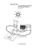
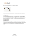
User Manual For Surface Mount Chip Component Test Fixture -- Shunt-Thru Configuration Test Fixture Overview Surface Mount chip capacitors (single or multi-layered), inductors or resistors can be measured on Inter-Continental Microwave's (ICM) Surface Mount Chip Component Test Fixture. The Test Fixture is designed as a solution for making measurements in a Shunt-Thru test configuration. Standard testing material is 25 mil Alumina microstrip. Adjustable guides on the fixture ensure accurate and repeatable placement of the chip. Deembedding with TRL / LRM or TOSL Calibration Standards removes the effect of the test fixture from your measurements. For custom sized devices, please contact the factory. Electrical Specifications SPECIFICATIONS: For Surface Mount Chip Component Test Fixtures: (25 mil Alumina Substrate) Type of RF Connector on Bolt-On Transition: APC-7 APC-3.5mm (f) Super SMA DC - 18 GHz DC - 26.5 GHz DC - 26.5 GHz Insertion Loss (each Transition): Uncalibrated < 0.5 dB < 0.5 dB < 0.5 dB Return Loss (each Transition): Uncalibrated > 20 dB > 20 dB > 20 dB Isolation: Uncalibrated, Typ. @ 18 GHz > 30 dB > 30 dB > 30 dB Room Temp (25 °C) Room Temp (25 °C) -55 °C to +125 °C Frequency Range: Temperature Range: Configuring Fixture for Specific Component Size When configuring the Test Fixture for a Specific Component Size (such as an 0805) follow installation below: Select and install the correct Midsection Assembly (ex: 0805 size) After doing each of these steps you are ready to begin testing your components! Choosing Midsection Assembly for Specific Component Size When testing a new specific component size, you need to select the correct corresponding Midsection Assembly. This insures that the component will make contact at the correct areas on the microstrip line and the ground pad. If this is not accomplished, you will have annomalies in your data due to incorrect spacing between the ground and RF signals on the device. After you have selected the correct Midsection you need to disassemble the fixture and replace the Midsection Assembly that is currently in there. There are 4-40 screws that hold the Midsection Assembly in place in the Test Fixture. Simply remove the screws and take the Midsection Asembly off the fixture. Take the Midsection Assembly currently in the fixture and place it in the provided case for safe keeping. Align the new Midsection Assembly in the Test Fixture. There is a red dot in one corner of the Midsection. This corner goes toward the back-left corner of the test fixture. Losely tighten the screws on the bottom plate and make sure the dielectric pusher will make contact in the correct location on the substrate of the Midsection. Once this is accomplished you can tighten the screws. Testing Components Testing components with this test fixture is a simple and straight forward manner. After installing the correct Midsection Assembly on the fixture you are ready to test your components. Simply place your component into the test fixture, using the guides as alignment tools. There should be very little slop in the placement of the device in order to insure accurate and repeatable testing. After the device is properly seated in the fixture, activate the press handle to move the dielectric pusher down onto the device. This spring loaded pusher should come down and push onto the component to hold it in place with a consistent amount of pressure. The device is now in place, and ready for whatever electrical test you need to run. When finished with the test, raise the pusher up with the handle, and remove the device, and then repeat the above steps. Calibration Procedure For Shunt-Thru Test Fixture Using Series 2000 Calibration Kits The first step in Calibrating the Test Fixture is to remove the transitions from the Test Fixture. For the Shunt-Thru Test Fixture calibration there are no special steps from the normal Bolt-On Transition Calibration. Just follow the steps outlined below. If you have any questions please contact ICM. First, you need to connect the cables from the Network Analyzer to the Transition Assemblies and install the Calibration Coefficients into the Analyzer. After connecting the cables to the Transition Assemblies you do NOT want to unattached the cables until after the testing is completed in order to ensure a consistent calibration. If the cables are removed, the calibration procedure must be redone in order to ensure that the Transitions are accurately calibrated. Turn off the calibration if one is on; set frequency, power level, attenuation, and other variables as required. Delete "cal set" if necessary. If you are using an HP 8510 Network Analyzer you can load the Calibration Coefficients from the supplied Disk or Tape. For the HP 8753 or HP 8720 Models you will need to enter the coefficients from the front panel. Perform the following steps to setup the Analyzer: Push the CAL hard key Push the proper CAL soft key (CAL 1 or CAL 2) Press the SET FREQ (LOW PASS) if required Press the TRL-2 PORT soft key Attach the Transitions to the Short Standard without disconnecting the cables from the Transitions. Push Parameter S11 hard key. Push Response AUTO hard key Uncorrected S11 should be displayed No big discontinuities should be visible Push Parameter S22 hard key Push Response AUTO hard key Uncorrected S22 should be displayed Push S11 REFLECT ICM SHORT soft key Push S22 REFLECT ICM SHORT soft key Push ISOLATION soft key Either push OMIT ISOLATION soft key or push FWD ISOL'N ISOL'N STD soft key and push REV ISOL'N ISOL'N STD soft key the push ISOLATION DONE soft key Push LINE ICM LINE soft key Remove the Transitions from the Short Standard, and move them to the Match Standard. Push Parameter S11 hard key. Push Response REF VALUE hard key Push Entry 0 x 1 hard keys Push Response SCALE hard key Push Entry 20 x 1 hard keys Return Loss should be greater than 20 dB up to 2.0 GHz Push Parameter S22 hard key Push Response REF VALUE hard key Push Entry 0 x 1 hard keys Push Response SCALE hard key Push Entry 20 x 1 hard keys Return Loss should be greater than 20 dB up to 2.0 GHz Push the MATCH soft key Move the Transition Assemblies to the Line 1 Standard. Push Parameter S21 hard key. Push Response AUTO hard key Uncorrected Insertion Loss should be displayed No big discontinuities should be visible Push LINE 1 soft key Move the Transition Assemblies to the Line 2 Standard. Push Parameter S21 hard key. Push Response AUTO hard key Uncorrected Insertion Loss should be displayed No big discontinuities should be visible Push LINE 2 soft key Push LINE ICM LINE DONE soft key Now you need to attach the Transition Assemblies to the Thru Standard. Now push Parameter S21 hard key. Push Response AUTO hard key Uncorrected insertion loss should be displayed No big discontinuities should be visible Push THRU ICM THRU soft key NOTE: DO NOT PRESS LOWBAND REFLECTION Push SAVE TRL 2 PORT soft key Push appropriate CAL SET soft key This will load the cal set and turn on the correction After the Calibration is complete and the Transitions are still on the Thru Standard, turn on S 21. The Insertion Loss should be zero. While still set up with the Thru Standard and S21 you can check the phase. It should also read zero. When done with the Calibration, move the Transitions back to the Test Fixture. Again, do NOT remove the cables from the Transitions during this move, or the cal will be inaccurate. Make sure that the RF Pins are centered on the microstrip line and that there is enough pressure between the RF Pin and the substrate. But use caution not to damage either of these parts. Inter-Continental Microwave 6501 W. Frye Road Chandler, AZ 85226 480-940-0740 fax 480-961-4754 www.icmicrowave.com [email protected]