1
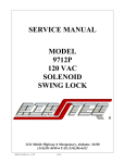
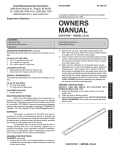
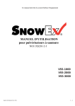
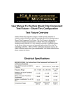
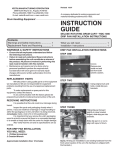
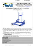
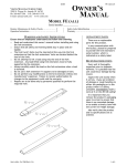
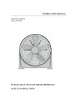
Revised 03-03
VESTIL MANUFACTURING COMPANY
2999 North Wayne St., Angola, IN 46703 USA
Phone (260) 665-7586 • Fax (260) 665-1339
E-mail: [email protected] • www.vestil.com
16-126-103
A company dedicated to solving ergonomic and material
handling problems since 1955.
Ergonomic Solutions
OWNER'S
MANUAL
A FRAME CART
MODEL AF-3048 & AF-3672
Contents
Safety Precautions .......................................
Receiving Instructions ..................................
Warranty .......................................................
Assembly Instructions ..................................
1
1
1
1
Assembly & Parts Drawing ........................... 2
Parts List ....................................................... 2
Warning Label Identification ......................... 2
SAFETY PRECAUTIONS
ASSEMBLY INSTRUCTIONS
Read owner's manual completely before operating unit!
• Never exceed the maximum capacity of 2,000 pounds.
• Load must be evenly distributed on platform to insure
stability.
• Always apply wheel brakes when unit is not being moved.
• Always operate unit on a level surface to insure stability.
• Use caution in moving a loaded unit; avoid obstructions
and floor defects.
• Remove weight and apply wheel brakes before removing
the top frame of the cart.
• Make sure all operator safety labels are in place (p.2).
TO INSTALL UPPER PORTION OF CART
E
Position pieces as shown on drawing, see page 2. Install
N
bolts and nuts, tighten finger tight. Once all the pieces are
G
losely bolted together tighten nut & bolt combo's.
L
I
TO INSTALL THE CASTERS
S
Two rigid casters are installed on one end of base frame and
H
two swivel casters at the other end.
1.) Place caster base plate into caster pad bracket.
2.) Insert 3/8"-16 UNC x 5" carriage bolt through the
square hole in caster pad to hold caster in place.
E
(Make sure head of carriage bolts towards outside
S
of cart).
P
3.) Place 3/8"-16 UNC locknut on each bolt and tighten
A
securely.
N
O
(Please refer to the next page for the assembly drawing)
L
RECEIVING INSTRUCTIONS
Every unit is thoroughly tested and inspected prior
to shipment. However, it is possible that the unit may incur
damage during transit. If damage is noticed when unloading,
make a note of it on the BILL OF LADING. Remove all
packing and strapping material, then inspect the unit again
for damage. IF DAMAGE IS EVIDENT, FILE A CLAIM WITH
THE CARRIER IMMEDIATELY!
WARRANTY
This product is warranted for 90 DAYS from date of
purchase to be free of manufacturing defects in material and
workmanship. The manufacturer's obligation hereunder is
limited to repairing such products during the warranty period,
provided the product is sent prepaid back to the factory.
This warranty does not cover normal wear of parts
or damage resulting from any of the following: negligent use
or misuse of the product, use or application contrary to
installation instructions, or disassembly, repair or alteration
by any person prior to authorization from a factory
representative.
A-FRAME CART
MODEL AF-3048 & AF-3672
1
A-FRAME CART
MODEL AF-3048 & AF-3672
ASSEMBLY & PARTS DRAWING
3
2
4
10
9
8
10
11
12
7
12
11
1
9
6
5
8
6
ITEM NO.
1a
1b
2a
2b
3a
3b
4
5
6
7
8
9
10
11
12
a/k
DESCRIPTION
Base (30"W x 48"L)
Base (36"W x 72"L)
Middle Brace (30"W x 48"L)
Middle Brace (36"W x 72"L)
Top (30"W x 48"L)
Top (36"W x 72"L)
Left Leg
Right Leg
Swivel caster w/ brake
Rigid caster
Carriage Bolts 3/8 - 16 x 5
Nut 3/8-16 Nylox
Bolt 5/16 - 18 x 1
Nut 5/16 - 18
Flat Washer 5/16
ENGINEER PART NO.
QTY.
16-514-033
16-514-021
16-032-003
16-032-001
16-032-010
16-032-011
16-514-096
16-514-095
16-132-053
16-132-022
21373
37024
11055
37021
33006
1
1
1
1
1
1
1
1
4
4
16
16
16
16
16
Available only with purchase of kit
WARNING LABEL IDENTIFICATION
MAKE SURE ALL WARNING LABELS ARE IN PLACE!
* Product safety signs or labels should be periodically inspected and cleaned by the product
users as necessary to maintain good legibility for safe viewing distance. ANSI 535.4 (10.21)
Contact manufacturer for replacement labels.
1
1
! CAUTION
USE CASTER
LOCK DURING
LOADING AND
UNLOADING
! PRECAUCIÓN
USE EL FRENO DE
LA RUEDA CUANDO
SE CARGUE Y
DESCARGUE
! PRUDENCE
UTILISER LES FREINS DE
ROULETTES LORS DU
CHARGEMENT OU DU
DÉCHARGEMENT 212
VESTIL MANUFACTURING COMPANY • Angola, In 46703 • Phone (260) 665-7586 • www.vestil.com
2
VESTIL MANUFACTURING COMPANY
2999 North Wayne St., Angola, IN 46703 USA
Phone (260) 665-7586 • Fax (260) 665-1339
E-mail: [email protected] • www.vestil.com
Soluciones Ergonómicas
Revisado 03-03
16-126-103
Una compañia dedicada a resolver problemas
ergonómicos y de manejo del material desde 1955.
MANUAL DEL
PROPIETARIO
CARRO DE MARCO DE A
MODELO AF-3048 & AF-3672
Contenido
Instrucciones de Seguridad ........................... 3
Instrucciones de Recibo ................................ 3
Garantia ........................................................3
Instrucciones de Ensamble ........................... 3
Ensamble y Dibujos de Partes ...................... 4
Lista de Partes .............................................. 4
Identificación de las Etiquetas de Aviso ....... 4
PRECAUCIONES DE SEGURIDAD
INSTRUCCIONES DE ENSAMBLE
Lea el manual del propietario completamente antes de
usar la unidad!
• Nunca exceda la máxima capacidad de 907 kg.
(2,000 lbs.)
• La carga debe de estar bien distribuida en la plataforma
para asegurar la estabilidad.
• Siempre ponga los frenos de las ruedas cuando la unidad
no este en movimiento.
• Siempre opere la unidad en una superficie a nivel para
asegurar la estabilidad.
• Vaya con cuidado cuando mueva la unidad cargada;
evite obstrucciones y defectos del piso.
• Quite el peso y ponga los frenos de las ruedas antes de
quitar el bastidor superior de la carreta.
• Asegurese de que todas las etiquetas de seguridad del
operario estan en su sitio (p.4).
1.) Remueva la cesta superior de la base de la carreta.
Deslice la cesta hasta los cuatro postes verticales
situados en la sección central de la base de la carreta.
(Suelte las tuercas y tornillos de la cesta para el
necesario ajuste.)
INSTRUCCIONES DE RECIBO
Cada unidad está inspeccionada a fondo y probada
antes del envio. Aun asi, es posible que la unidad se dañe
durante el envio. Si ve algún daño durante la descarga
anótelo en el RECIBO DE ENVIO. Quite todo el material de
empaquetado y las correas, inspeccione por daños. SI HAY
DAÑOS EVIDENTES, ARCHIVE UNA RECLAMACION
CON EL TRANSPORTISTA IMMEDIATAMENTE.
2.) Instale dos ruedas giratorias en el mismo extremo de
la base donde están los soportes redondos, y dos
ruedas rígidas en el otro extremo. Ponga la placa
almohadilla entre la rueda y la carreta e inserte un
tornillo de 0.95 cm-16 x 12.7 cm a través del agujero
cuadrado en la placa almohadilla para aguantar la rueda
E
en su sitio. (Asegurese que la cabeza del tornillo está
S
hacia dentro de la mesa). Ponga una tuerca de 0.95 cmP
16 en cada tornillo y apriete hasta que esté seguro.
A
N
3.) Ponga en la posición derecha y asegurese que las
O
ruedas no se mueven.
L
4.) Ponga el tubo redondo negro entre los soportes
redondos e inserte una varilla de 12.7 cm de diametro
a traves de los soportes y el tubo, dejando un espacio
en cada extremo. Glopee los tapones hasta el final
de cada varilla. Quite el tope de las ruedas.
(Porfavor refierase a la página siguiente para el dibujo de ensamble)
GARANTIA
Este producto está garantizado durante 90 DIAS
desde la fecha de compra de estar libre de defectos de
material y mano de obra. La obligación del fabricante está
limitada a reparar tales productos durante el periodo de
garantia, provisto que el producto se envie previo envio
flete pagado a la fábrica.
Esta garantia no cubre el gasto normal de partes o
daños que resulten de lo siguiente: uso negligente o mal
uso del producto, uso o aplicación contraria a las
instrucciones de instalación, o desensamble, reparaciones
o alteraciones por cualquier persona antes de la previa
autorización de un representante de la fábrica.
CARRO DE MARCO DE A
MODELO AF-3048 & AF-3672
3
CARRO DE MARCO DE A
MODELO AF-3048 & AF-3672
ENSAMBLE & DIBUJO DE PARTES
3
2
4
10
9
8
10
11
12
7
12
11
1
9
6
5
8
6
PARTIDA
1a
1b
2a
2b
3a
3b
4
5
6
7
8
9
10
11
12
a/k
DESCRIPCIÓN
Base (30"W x 48"L)
Base (36"W x 72"L)
Middle Brace (30"W x 48"L)
Middle Brace (36"W x 72"L)
Top (30"W x 48"L)
Top (36"W x 72"L)
Left Leg
Right Leg
Swivel caster w/ brake
Rigid caster
Carriage Bolts 3/8 - 16 x 5
Nut 3/8-16 Nylox
Bolt 5/16 - 18 x 1
Nut 5/16 - 18
Flat Washer 5/16
NO. DE INGENIERO
CTD.
16-514-033
16-514-021
16-032-003
16-032-001
16-032-010
16-032-011
16-514-096
16-514-095
16-132-053
16-132-022
21373
37024
11055
37021
33006
1
1
1
1
1
1
1
1
4
4
16
16
16
16
16
Disponible solo con la compra del juego
IDENTIFICACION DE LAS ETIQUETAS DE AVISO
ASEGURESE DE QUE TODAS LAS ETIQUETAS DE AVISO ESTAN EN SU LUGAR
* Las etiquetas o las señales de seguridad del producto deben de ser
inspeccionadas periodicamente y deben de limpiarse por los
usuarios del producto como sea necesario para mantener una buena
legibilidad desde una distancia de seguridad. ANSI 535.4 (10.21)
Contacte al fabricante para reemplazo de etiquetas.
1
1
! CAUTION
USE CASTER
LOCK DURING
LOADING AND
UNLOADING
! PRECAUCIÓN
USE EL FRENO DE
LA RUEDA CUANDO
SE CARGUE Y
DESCARGUE
! PRUDENCE
UTILISER LES FREINS DE
ROULETTES LORS DU
CHARGEMENT OU DU
DÉCHARGEMENT 212
VESTIL MANUFACTURING COMPANY • Angola, In 46703 • Phone (260) 665-7586 • www.vestil.com
4