1
US007949777B2
(12) Ulllted States Patent
(10) Patent N0.:
Wallace et a].
(54)
(45) Date of Patent:
COMMUNICATION PROTOCOL FOR
6,223,211 B1
CONTROLLING TRANSFER OF TEMPORAL
4/2001 Hamilton etal.
19329911
6,418,150 B1
W200, Stilts“ *1 '
SYNCHRONIZATION WITH A PERIODIC
6,522,649 B1 *
2/2003
REFERENCE SIGNAL
6,570,624 B2
6,665,450 B1
Inventors: Harry
Ron Wallace,
Der’ Westford’
Lexington,
MAMA
GS)’
(US);
. Mam“
-
2002/0009049
,
,
A1 *
Corbett,
Fetters, Tewksbury,
Westford, MA
MA (U S) Terrence
2002/0141439 A1
2002/0154792
(73) Assignee: Avid Technology, Inc., Burlington, MA
EP
JP
*
~
.
~
( ) Not1ce.
~
~
Stallkamp ................... .. 370/389
5/2003 Cornog et a1.
12/2003 Cornog et a1.
1/2002 Nomura
glartcla
asumooe
et ta1~
......................
a.~~~~~~~~~~~ ..~~ 370/229
10/2002 Cornog et a1.
FOREIGN PATENT DOCUMENTS
(US)
'
Subject' to any d1scla1mer,~ the term ofthis
JP
JP
0873019 A2
10/1998
HEI 11-346319
12/1999
2001-230750
8/2001
2001626863
120001
patent 1s extended or adjusted under 35
_
U.S.C. 154(b) by 2620 days.
(Con?rmed)
(21) Appl. No.2 10/2s6,215
.
(22)
May 24, 2011
g}
DATA 0vERA BUS BETWEEN DEVICES IN
(75)
US 7,949,777 B2
OTHER PUBLICATIONS
_
3D Sound Surge Press Release, Wired Unleashes the Power of Digital
F?ed'
NOV‘ 1’ 2002
(65)
Video Streaming Media Announces Availability of Fire Wired AV
Prior Publication Data
Us 2004/0086000 A1
and Fire Wired DV’ Jan‘ 5’ 2000'
May 6, 2004
(Continued)
( 51 )
Int CL
Primary Examiner * Chi H Pham
(52)
G06F 15/16
(2006.01)
US. Cl. ....... .. 709/232; 709/231; 370/282; 370/503
Assistant Examiner * Weibin Huang
(74) Attorney, Agent, or Firm i Oliver Strimpel
(58)
Field of Classi?cation Search ................ .. 370/464,
370/498, 503, 276, 282; 709/230, 231, 232,
1_
_
?l f
See app lcanon
(56)
1
7091:2133’ 234’ 245
e or Comp ete Seam
lstory'
computer and the peripheral device so as to maintain synchro
niZation to a periodic reference signal. The protocol involves
transferring ?oW control messages betWeen the peripheral
U S PATENT DOCUMENTS
' '
5241382 A
631053083 A *
_
8/1993 P k t 1
@1999
device and the host computer, alloWing the peripheral device
e a'
to control hoW and When the host computer sends the uncom
8/2000 Kurtze et a1. ................. .. 710/29
6,134,607 A
10/2000 Frink
6,141,691 A *
10/2000 Frink et al. .................. .. 709/233
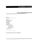
200
\
HOST
COMPUTER
ABSTRACT
peripheral device to control the How of data betWeen a host
References Cited
5’9 15’ 130 A
(57)
A communication protocol over the serial bus alloWs a
204
PreSsed audlo and Vldeo dam
/
25 Claims, 11 Drawing Sheets
202
PERIPHERAL
DEVICE
/20s /
OTHER
DEVICE
\208
210
PERIODIC
REFERENCE
SIGNAL
212
US 7,949,777 B2
Page 2
FOREIGN PATENT DOCUMENTS
W0
W0
W0
W0
W0
W0
WO
WO
WO
WO
WO
WO
99/52290
00/60478
01/24479
01/26292
01/59965
01/78400
10/1999
10/2000
4/2001
4/2001
8/2001
10/2001
OTHER PUBLICATIONS
Omneon Video Networks, Broadcast Hardware April Issue, “IEEE
1394 A Core Technology”, Edward Hobson, 2001, 3 pages.
Omneon Video Networks, “Network Architectures”, Peter Powell,
Sep. 1999, 4 pages.
ProMaX, DA-MAX Comprehensive Breakout Box AudioVideo Digi
tal Format Converter, Data Sheet, 2 pages.
ProMaX, DA-MAX Speci?cation, 2002, 2 sheets.
ProMaX DA-MAX Installation Guide Preliminary, Oct. 29, 2001, 10
pages.
Canpopus ADVC-100 Advanced Digital Video Converter Data
Sheet, Nov. 2001, 2 pages.
DV-Bridge DV to/ From Digital Audio-Video Codec Speci?cation, 2
pages.
DV-Bridge DV to/ From Digital Audio-Video Codec Speci?cation, 3
pages, 1999-2001 Miranda Technologies Inc.
Dynamic Network Factory, Firewire IEEE-1394 High Performance
Serial Bus, 12 pages, 1998-2002, Dynamic Network Factory, Inc.
Laird Telemedia LTM-5500 Blue Flame Pro IEEE 1394 (DV) Bi
Directional Media Converta Data Sheet, 2 pages.
Laird Telemedia Professional Firewire (IEEE 1394) Media Convert
ers, 2 pages.
Laird Telemedia Model LTM-5500 User Manual, 2001, pp. 1-6.
Leitch Multi-Function Digital/Analog NV SynchroniZer DPS-575
Product Catalog, 2002.
MacInTouch Fire Wire Guide, 2000, 13 pages.
Miranda Technologies Inc. DV-Bridge Guide to Installation and
Operation M142-9900-301, Jul. 2000, 11 pages.
Omneon Video Networks, “Technology Brief-The Omneon Video
Area Network and Storage Area Networks”, New Release, 2001, 3
pages.
PowerR, Director’s Cut, Product Brochure, 3 pages.
Streaming Media and Video Professional, Firewired DV and
Firewired AV press release, 2 pages.
SourceForgenet: DV Transmission over IEEE-1394, Tips and
Tricks, 4 pages.
Synthetic Aperture, FireWire to Video Conversion Solutions, Data
Sheet, Oct. 13, 2001, 6 pages.
TVone Multimedia Solutions, DV-2001 DV-Analog Converter,
Speci?cation, 2 pages.
TechEncyclopedia, TCP/IP abc’s, 9 pages.
Videonics, Micro-PACE product brochurs, Feb. 15, 2002, 4 pages.
U.S. Appl. No. 09/054,864 Non-Final Of?ce Action dated Jan. 3,
2007, 17 pgs.
U.S. Appl. No. 09/054,864 Final Of?ce Action dated Jul. 2, 2007, 14
PgS~
U.S. Appl. No. 09/054,864 Final Of?ce Action dated Jan. 28, 2008,
15 pgs.
U.S. Appl. No. 09/054,864 Final Of?ce Action dated Jan. 6, 2009, 15
pgs.
* cited by examiner
US. Patent
100\
May 24, 2011
US 7,949,777 B2
Sheetl 0f11
/102 (_LOTHER I/O
106
DV OR OTHER
FORMAT
HOST
COMPUTER
FORMATS
PERIPHERAL
DEVICE
DV,
DV
—--->
I106
UNCOMPRESSED
OR OTHER
FORMAT
110
PERIODIC
REFERENCE
SIGNAL
FIG. 7
200\
HOST
COMPUTER
202
204
/
PERIPHERAL
DEVICE
/206 /
OTHER
DEVICE
\208
210
PERIODIC
REFERENCE
SIGNAL
FIG. 2
212
US. Patent
300
May 24, 2011
Uncompressed
\
Sheet 2 0f 11
302
Video and Audio
306
\
304
Anolog Video
and
and Device Control
HOST
US 7,949,777 B2
Audio Outputs
PERIPHERAL
/
DEVICE
308
Compressed Video
with Audio and
Device Control
FIG‘. 3
400 \
Compressed
Video,
Audio, and
Device Control
HOST
/
402 \ 406>/ Anolog
and Video
PERIPHERAL
Audio Outputs
DEVICE
404
Compressed Video
408
FIG. 4
with Audio and
Device Control
US. Patent
500
May 24, 2011
Compressed
\
Sheet 3 0f 11
Video, Audio, and
'
Devlce Control
502
US 7,949,777 B2
506
\
.
.
Composlte Vldeo,
Analog Audlo
PERIPHERAL
510
or/Svideo Video,
Compressed Video
508
Audio, Device
Control
/630
HOST
COMPUTER
640
540
600 \
/ 610
PERIPHERAL
DEVICE
PERIODIC
REFERENCE
PERIPHERAL
DEVICE
\ 620
SIGNAL
FIG. 6
US. Patent
May 24, 2011
Sheet 5 0f 11
m.t5oz0 OHmn3=>Olm
/
/mom
P.-5E0J P.15901
2m\ 8.27 mo zm mo zm m5
>0
\85%N5
‘Om.
co/
m
FmOI
mco
US 7,949,777 B2
NQ /
US. Patent
May 24, 2011
1102
d
1104
t'
t'
Sheet 9 0f 11
\
_|D
1106
\
tl
US 7,949,777 B2
1108
1110
\
,t t
/”00
\
d
'
. 1.28.291 XMAA; fiW/ZZ/
dev|ce__stotus
/ 1115
FIG. 11
1202
1204
\
\
1206
\
1208
\
1210
\
/ 1200
\\\\,\§XNP??"—£BE. . .\,. . k /
reserved
transfer-rote
||||||1|||11|1|
Stre°m_
1214
||1|||1|c|°FrPt|||//
1212/
I
O to 255 Stream Descriptors
l/1g15
. ?ts/T662. .//
FIG. 12
1.300
1302\
1J04\
stream-ID stream-speci?c duto
pocket-count
||1|1||111|||1||||||||1|1|1||
FIG. 13
/
US. Patent
May 24, 2011
Sheet 10 0f 11
1404\ 1402\
NAME
VFiELDi
VFIELDZ
VFRAME
SYSTEM
AUXILIARY
A1
A2
A3
A4
A5
A6
A7
A8
VALUE
1
2
3
US 7,949,777 B2
1406\ 1/1400
DESCRIPTION
field 1 video data
field 2 video data
full frame video data
I52
33
system data
auxiliary data
64
65
66
67
68
69
70
71
A1
A2
A3
A4
A5
A6
A7
A8
FIG‘. 14
audio
audio
audio
audio
audio
audio
audio
audio
data
data
data
data
data
data
data
data
US. Patent
1502
May 24, 2011
1504
\
\
Sheet 11 0f 11
1506
\
US 7,949,777 B2
1508
\
,
1510
/1500
\
MN’ 2152' w fr,
\\\\\\.\\.\1 1TsR§,\\\\ \H\/1514
O to 1024- Doto quodlets (isochronous)
:
or
{/4512
O to 512 Data quodlets (asynchronous)
FIG‘. 15
1600
1602
1604
\.
\
1606
1608
,\ ,\
1610
/
\
7/AdsEa-‘s V4391??? 12d; .81. _
\x\\.\\\\.\1e:w1-.2R§\\ .\\\\\.>/
1612
O to 1024- Doto quodlets (isochronous)
:
or
|r---1614
O to 512 Data qucldlets (asynchronous)
/
/
/
/
/
/
//l/fl/l/f/lA/l/f/I
o_CRC (omitted l/l
if doto_length
== o)///1616
l1/l l/lx/l/b/l/l l/
FIG. 16
US 7,949,777 B2
1
2
COMMUNICATION PROTOCOL FOR
CONTROLLING TRANSFER OF TEMPORAL
DATA OVER A BUS BETWEEN DEVICES IN
SYNCHRONIZATION WITH A PERIODIC
REFERENCE SIGNAL
61883 standard provides a technique for synchronizing these
clocks, different time bases generally exist on different
devices on the bus due to jitter and phase differences betWeen
the clocks. A consequence of the different time bases is that a
host either transmits more data packets than a transcoder can
consume or transmits too feW data packets to the transcoder,
causing a frame to be repeated or dropped. To address this
BACKGROUND
problem, a host is required to periodically send empty data
packets and to use a presentation time stamp (the SYT ?eld)
in a packet of each frame. The presentation time stamp des
ignates to the transcoder a point in time When the frame
Peripheral devices that process video and audio data com
monly are connected to a host computer either to perform
functions not performed by the host computer or to convert
the video and audio data betWeen digital and analog formats.
The connection betWeen the peripheral device and the host
should be displayed. HoWever, the time stamp is generated by
computer is typically provided by a bus over Which commu
nication is performed using packets. Example types of a bus
include, a parallel bus, such as a peripheral component inter
connect (PCI) bus, a serial bus, such as an lEEE-l394 com
pliant bus, or a computer network, such as Ethernet.
Video and audio data are typically in a standard format,
such as the format described by “Speci?cations of Consumer
20
Use Digital VCR’s using 6.3 mm magnetic tape” of the HD
Digital VCR Conference dated December 1994, also called
the “Blue Book,” or by SMPTE 3 l 4M-l 999 or by lEC-6 l 834,
Which describe video and audio data in a format that is com
monly called “DV.”Video data may be compressed or uncom
devices do not send timestamps, and some devices do not
25
pressed. Audio data typically is uncompressed.
ers cannot be used to reliably generate a synchronous video
signal for playback on a video monitor or for recording to
audio data is a transcoder. A transcoder typically receives
compressed digital video data and audio data, such as DV,
30
processes the data for output. In particular, the video data is
converted into an analog video signal for output to a video
tape, or to synchroniZe playback of audio and video material
With an external synchroniZed video device.
Current transcoder designs also do not enable a host to
connect to another device through the transcoder in a manner
that alloWs the host to communicate directly to the other
device, such as a video monitor or camcorder. The audio data
is converted into an audio signal for output to an audio device,
such as a set of speakers. Such a transcoder also may receive
attempt to process received timestamps. Because frames may
be dropped or repeated using these techniques, such transcod
An example peripheral device that processes video and
over a serial bus, such as an lEEE-l394 compliant bus, and
a sender using the sender’s bus timer clock, but is used by the
recipient using the recipient’s bus timer clock. Thus, even if
the number and frequency of the transmission of the empty
data packets is calculated carefully in advance of transmis
sion, on average, the empty data packets merely extend the
period of time before a frame is dropped or repeated. The use
of empty data packets does not solve the problem created by
the different time bases on sending and receiving devices.
Another problem With time stamps is that not all commer
cially available devices support use of time stamps. Some
device, yet alloW the transcoder to modify data in packets sent
35
an input analog video signal and audio signal and generate
compressed digital video data and audio data, such as DV, that
to the other device.
SUMMARY
is transferred to the host computer over a serial bus, such as an
lEEE-l394 compliant bus.
Many systems currently are available that transfer video
40
temporal data betWeen devices over a bus to maintain syn
and audio data betWeen a peripheral device, such as a cam
corder or a transcoder, and a host computer. The host com
puter may be used for any of a number of purposes, such as
chroniZation of the temporal data With the periodic reference
signal. FloW control messages are sent betWeen devices,
alloWing a device that receives the periodic reference signal to
video and audio editing. When using DV, DV commonly is
transferred betWeen the host computer and a peripheral
device using an lEEE-l394 compliant bus. A standard is
A communication protocol is provided to alloW a device
that receives a periodic reference signal to control the How of
45
control hoW and When the data is sent over the bus. For
example, a peripheral device that receives a periodic refer
de?ned for transporting DV streams over an lEEE-l394 com
ence signal may send ?oW control messages to a host com
pliant bus, called lEC-6l 883. In an editing system that edits
puter to control the How of data from the ho st computer to the
peripheral device. Different types of temporal data, such as
stored DV and outputs DV over an lEEE-l394 bus using
lEC-6l883, the host ?rst decompresses the DV, performs
50
editing operations on decompressed data, and then com
sent using an asynchronous protocol, Whereas temporal data
presses the results back into DV before transferring DV over
the lEEE-l394 bus. This process requires resources of the
host computer to be used for compression, thus limiting the
real-time processing capabilities of the host computer. Thus,
55
such as compressing the video data or generating an analog
video signal. Video and audio data may be transferred as
another device. Further, to produce video in any output format
other than DV, such as an analog video signal, the DV version
also must be decompressed ?rst. Decompression of DV and
encoding of the results in an analog video signal generally is
performed by a transcoder.
time base, Which generally is faster or sloWer than the time
base on other devices on the same bus. Although the IEC
are sent using an isochronous protocol.
Uncompressed video and audio data are transferred from
the host computer over a serial bus to the peripheral device,
Where the peripheral device performs operations on the data,
a DV version of the entire program often is created and stored
in a data ?le before it is transferred from the computer to
An lEEE-l394 compliant device transfers data based on a
local time base using What is called a bus timer clock. As a
result, each device attached to an lEEE-l394 bus has its oWn
audio and video data, may be sent as separate data streams.
Using the lEEE-l394 protocol, the How control messages are
separate streams. By transferring uncompressed video data,
the host computer does not need to consume resources to
compress the video data, thus alloWing those resources to be
used for more creative operations on the video and audio data.
Further, by transferring uncompressed video data, the periph
eral device can generate video data in many output formats
65
Without ?rst decompressing the video data. The peripheral
device also may output video and audio data using a standard
protocol over a standard bus. For example, the peripheral
US 7,949,777 B2
3
4
device may generate DV from the uncompressed audio and
video data, and output the DV using IEC-61883 over an
IEEE-1394 compliant bus.
A peripheral device that synchronizes transfer of data from
the host computer With a periodic reference signal also can be
FIG. 9 is a block diagram of a peripheral device for the
mode of operation shoWn in FIG. 5.
trated in FIGS. 7-9.
used to synchronize data transfer to another device, such as a
transcoder or camcorder or deck, that is connected to the
mat.
FIGS. 10A-10B are a more detailed block diagram of a
peripheral device incorporating the modes of operation illus
FIG. 11 illustrates an example synchronization packet for
peripheral device. For example, the peripheral device may
FIG. 12 illustrates an example preamble packet format.
encode the uncompressed audio and video data received from
the host computer as a video signal. The peripheral device
then outputs the video signal to the other device. The other
FIG. 13 illustrates an example stream descriptor format.
FIG. 14 is a table of stream identi?ers.
FIG. 15 illustrates an example data packet format.
FIG. 16 illustrates an example null packet format.
device may provide the periodic reference signal. For
example, if the other device is a camera, a composite video
output signal from the camera can be used as the periodic
reference signal. As a result, transfer of data from the host to
the peripheral device and then to the camera is synchronized
DETAILED DESCRIPTION
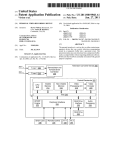
FIG. 1 illustrates a system in Which a host computer 100 is
connected to a peripheral device 102 by a bus 104, such as an
to the camera.
Such a peripheral device also alloWs a real time digital cut
IEEE-1394 compliant bus. The host computer typically
to tape to be performed. In particular, by transferring uncom
pressed data from the host computer to the peripheral device
during playback in synchronization With a periodic reference
includes storage for storing video data and audio data in data
?les using a ?le system of the operating system of the com
puter. An editing system is provided on the host computer to
alloW editing of a program using the video data and audio data
signal, the host computer can process effects in real time. The
peripheral device may generate a DV output from the uncom
pressed data. This DV output can be provided over an IEEE
1394 compliant bus to a recording device such as a DV deck
20
25
temporal media, and a range Within the data ?le. A playback
system also is provided for playing back the edited program in
full motion at full resolution. The playback system alloWs an
or camcorder. If this DV deck or camcorder has a composite
video output signal, then this output signal from the deck or
camcorder may be used as the periodic reference signal. The
peripheral device also may act as a bridge betWeen the host
30
video data.
The bus may be any type of bus over Which communication
35
peripheral device or if the packet is to be processed by the
interface for sending packets to and receiving packets from
peripheral device to create one or more neW packets to be
40
the peripheral device may decompress compressed video data
received from the host and output data packets that include
uncompressed video data to the other device. From the per
spective of the ho st, the peripheral device behaves as if it Were
the other device. From the perspective of other device, the
the device over the bus. A buffer in memory commonly is
connected to transfer data to the bus interface for transmission
as a plurality of packets. This buffer Will receive, for example,
data from the playback application for transfer to the device.
45
A driver, a form of softWare that acts as a controller, for the
bus interface also is on the host computer and alloWs the host
computer to implement communication protocols, such as the
protocol described herein, over the bus.
data packets appear to be from a host device.
BRIEF DESCRIPTION OF THE DRAWINGS
The host computer may receive data over the bus from the
peripheral device. The ho st computer may send data over the
FIG. 1 is a block diagram of a system in Which a host
computer is connected to a peripheral device.
FIG. 2 is a block diagram of a system in Which a host
computer is connected to a peripheral device that is synchro
nized With another video device.
50
FIG. 3 is a more detailed block diagram of a mode of
55
bus to the peripheral device. The host computer and periph
eral device may exchange several kinds of data including
video data, audio data and other temporal data and other
content. Video data may be either compressed or uncom
pressed, and may be combined With or separate from audio
data and other related time-based media. Audio data typically
is uncompressed, but may be compressed. The invention is
operation of the peripheral device as in FIG. 1.
FIG. 4 is a more detailed block diagram of another mode of
operation of the peripheral device as in FIGS. 1 and 2.
FIG. 5 is a more detailed block diagram of another mode of
operation of the peripheral device as in FIGS. 1 and 2.
FIG. 6 is a block diagram of a mode of operation using tWo
is performed using packets and Which can transmit data for
temporal data, such as video data and audio data, at a rate
faster than the sample rate of the temporal data, such as the
frame rate of the video data. The ho st computer includes a bus
eral device determines if the packet is directed to a device
connected on the other port or if the packet is directed to the
output to the device connected on the other port. For example,
editor to vieW the program that has been edited. If the video
data is compressed, the playback system decompresses the
video data, and performs any effects on the decompressed
computer and the other device. In particular, the peripheral
device may implement a protocol over the serial bus betWeen
the host computer and the peripheral device and a protocol
over another serial bus betWeen the peripheral device and the
other device. After receiving a packet at one port, the periph
With effects to be performed on the video data. Such an
editing system typically represents a program as a sequence
of clips, Wherein a clip is a reference to a data ?le containing
60
not limited to any particular format of video data or audio data
or other temporal data.
Data is transferred over the bus 104 in the form of packets.
A packet is a unit of transmission of data that includes both
data and routing information, such as an address of a node on
the bus. A packet also may indicate a type of the packet if the
peripheral devices that both receive data from a host com
puter.
communication protocol alloWs different types of packets to
FIG. 7 is a block diagram of a peripheral device for the
mode of operation shoWn in FIG. 3.
FIG. 8 is a block diagram of a peripheral device for the
mode of operation shoWn in FIG. 5.
be transmitted. A packet also may include error correction
codes and other data. The form and content of each type of
packet typically is speci?ed as part of a communication pro
tocol that is described in more detail beloW.
65
US 7,949,777 B2
6
5
The peripheral device may have several inputs 106 to
202 and the other device 212. The periodic reference signal
receive data in any of a number of formats from a source, such
as video and audio data from a tape deck. The peripheral
may be generated by the peripheral device 202, the other
device 212, or may come from another source.
device also may have several outputs 108 to send data in any
Examples of other devices 212 that may be connected to
of a number of formats to a receiver, such as video and audio
data to a monitor and speakers or to a tape deck. For example,
the peripheral device may send DV to a DV device, such as a
DV camcorder or DV tape deck, or may receive DV from a
the peripheral device 202 include but are not limited to a
transcoder, video display, tape deck, camera or video process
ing equipment. For example, the peripheral device may
receive uncompressed video and audio data from the host
computer. The peripheral device may generate from this data
an analog video and audio signal that is synchronized With the
periodic reference signal and that is output to the other device.
The various functions of the peripheral device also may be
integrated Within the other device to produce a single device
that operates to provide the combined functions. Similarly,
the various functions of the other device may be integrated
Within the peripheral device to produce a single device that
operates to provide the combined functions. Thus, a
transcoder, video display, tape deck, camera or other video
DV device. Examples of other video and audio input and
output formats include, but are not limited to, analog formats
such as composite video, component video (such as YCrCb
andYUV video) and S-Video, and digital formats, both com
pressed and uncompressed, both standard and proprietary,
such as MPEG-2, SMPTE-l25M, SMPTE-260M, SMPTE
264M, SMPTE265M, SMPTE-267M, SMPTE-274M, and
SMPTE-279M, among others. The peripheral device also
may internally generate or receive from an external source a
periodic reference signal 110 foruse in controlling data trans
fer from the ho st. This periodic reference signal has a rate that
corresponds to the desired rate of the temporal data, such as a
?eld or frame rate of video, that is output by the peripheral
processing equipment could incorporate the functions of the
20
peripheral device as described herein. Three example opera
tional modes for such a peripheral device include uncom
device. The periodic reference signal may be generated by an
pressed playback mode, digital cut mode, and capture mode,
accurate crystal clock generation circuit. Such a circuit may
be internal to the peripheral device or external to the periph
eral device. The periodic reference signal also may be gener
ated by using a video decoder that decodes a received com
as Will be described in connection With FIGS. 3-5.
In uncompressed playback mode, shoWn in FIG. 3, the ho st
25
posite video signal to generate a vertical synchronization
signal (V SYNC), a horizontal synchronization signal
system 300 passes a stream of uncompressed video and audio
and/or device control commands to the peripheral device 302
over the bus 304. For playback during editing, the uncom
pressed stream may be fractional frame (such as 1A-frame) or
composite video signal used for this purpose is commonly
full-frame, depending on a user-de?ned setting. For digital
cut mode discussed beloW, full-frame mode is the default
setting. The peripheral device may include a resizer to scale
called a genlock, RS 1 70, black burst or house sync signal, and
may or may not include active video. The signals output from
the decoder may be provided as inputs to a video encoder to
fractional-frame video to full-frame video. The peripheral
device may generate an analog video and audio output 306
using the uncompressed stream. A video WindoW on the desk
(HSYNC), a pixel clock (such as 27 MHZ for NTSC/PAL
standard de?nition video) and a burst phase signal. Such a
generate output video that is in synchronization With the
30
35
received composite video signal.
Each ?eld boundary or frame boundary, or other desig
nated boundary in time that can be derived from the periodic
reference signal, may be used to de?ne a data interval. A data
interval is a period of time Within the temporal data that
corresponds to the periodic reference signal, such as a frame
top of the host computer may play in synchronization With the
outputs of the peripheral device. The peripheral device may
create a DV or other compressed output 308 by encoding the
uncompressed stream using an encoder on the peripheral
device. By providing su?icient buffering, the compressed
40
output may be kept in synchronization in spite of latencies
incurred by encoding the uncompressed stream on the periph
eral device.
or ?eld of video data, or audio or metadata that corresponds to
the frame or ?eld of video data. The communication protocol
In this mode, editing, playback and creation of output
described beloW utilizes a data interval as a basis for transfer
the periodic reference signal.
video and audio With real-time effects can be provided. In
particular, because the host does not compress the video and
audio stream after application of a real-time effect, the
The peripheral device may be used to capture or playback
multiple streams of audio and video data for the host com
back to the peripheral device, Which in turn can encode the
of data from the ho st to the device to synchronize the data With
45
uncompressed output is transferred in real time during play
puter. For capture, the peripheral device receives data from
one or more of its inputs and transfers the received data to the
50
host computer over the bus. For example, the peripheral
device may receive a DV stream, Which it transfers directly to
the host computer. The peripheral device may receive an
analog video and audio stream, Which it then converts to a DV
stream that is transferred to the host. In the playback mode,
the peripheral device receives a stream of video and audio
data from the host computer over the bus. This stream may be
converted into any of a number of formats for output to
another device. For example, the peripheral device may con
vert the received stream into an analog video and audio signal
55
camcorder has a composite video output signal, then this
output signal from the deck or camcorder may be used as the
60
periodic reference signal.
Playback of video may occur in one or more of a desktop
or into a DV stream for transmission to a recording device or
WindoW on the host computer, composite or S-Video outputs
306 on the peripheral device, and a DV output 308 via a
lEEE-l394 compliant bus on the peripheral device, or on
Referring to FIG. 2, the peripheral device 202 can synchro
outputs 208) to the peripheral device 202, to a periodic refer
ence signal 210 that is received by both the peripheral device
effects in real time. The peripheral device may generate a DV
output from the uncompressed data. This DV output can be
provided over an lEEE-l394 compliant bus to a recording
device such as a DV deck or camcorder. If this DV deck or
to a monitor and speakers.
nize data transfer over the bus 204, from the host computer
200 to another device 212 that is connected (via inputs 206 or
uncompressed stream for output. Such operation also alloWs
a real time digital cut to tape to be performed. In particular, by
transferring uncompressed data from the ho st computer to the
peripheral device during playback in synchronization With a
periodic reference signal, the host computer can process
65
other outputs of the peripheral device. Playback of audio may
occur through one or more of the analog outputs, DV outputs
or digital outputs (not shoWn).
US 7,949,777 B2
8
7
nicate packets directed to the host computer using the proto
In another mode shown in FIG. 4, a digital cut of a com
pressed stream rendered by the host computer 400 and/or
device control commands is provided to the peripheral device
col over the second serial bus.
In general, the peripheral device receives messages from a
host at one port of the peripheral device, translates the mes
sage, then send a message to the other device from another
port of the peripheral device. The translation involves at least
translating any node address in the message so that it is
402 over the bus 404. In this mode, any effects are rendered
and the rendered images are compressed at the ho st computer
and stored in the data ?les before the transfer. The compressed
stream is read by the host computer 400 from its data ?les and
transmitted to peripheral device 402. The compressed stream
may be transmitted to the peripheral device using the syn
properly directed to the other device through the other port.
Translation may also involve other processing to be per
chronized protocol described beloW. The synchronized pro
formed on the data in the packet such as conversion from one
data format to another.
tocol is used to transfer the DV stream for playback on a
synchronized device such as a television monitor.
Playback of video may occur in one or more of a desktop
Conversely, the peripheral device receives messages from
the other device at one port of the peripheral device, translates
WindoW on the host computer, composite or S-V1deo outputs
406 on the peripheral device, and a DV output 408 via the
IEEE-l394 compliant bus on the peripheral device, or on
the message, then sends a message to the host from another
port of the peripheral device. Again, the translation involves
at least translating any node address in the message so that it
other outputs of the peripheral device. Playback of audio may
is properly directed to the host through the other port, and
may involve converting data formats or other processing of
occur through one or more of the analog outputs, DV outputs
or digital outputs (not shoWn). The analog outputs are created
by having the peripheral device decode the incoming com
pressed stream using a decoder on the peripheral device, then
encoding the decoded data using a video encoder. To perform
a digital cut to a DV tape, the peripheral device performs
device control operations on the DV device (not shoWn)
attached to the DV output 408, and outputs the DV data
directly as received from the host.
In this mode the compressed output from the peripheral
device plays in synchronization With the video in the desktop
WindoW on the host computer. By providing su?icient buff
ering in the host, the latencies arising from decoding the DV
stream and encoding the analog outputs on the peripheral
device may be overcome to synchronize the analog outputs
With the video in the desktop WindoW.
A third mode of operation is capture, shoWn in FIG. 5.
Capture employs one of several different input sources (506,
the data in the message.
20
received on one port, the process for that port invokes a
25
30
HoWever, application level acknoWledgements are passed
from the ho st to the other device, and from the other device to
the host, through the peripheral device using the node trans
35
40
bus 504. The DV stream may be transferred to the host system
using the synchronized protocol described beloW. During
transfer of DV data to the ho st computer, the peripheral device
may decode the DV stream and encode the decoded data to
translator process Which translate the message and sends the
translated message to the other process for the other port.
Whether packets ?oW from the host to the other device or
from the other device to the ho st, packets received by the ho st,
peripheral device or other device are locally acknoWledged
using a loW level protocol, such as the link layer protocol.
508, 510) of the peripheral device 502, such as composite
video, S-Video video, and DV video and audio inputs. DV
device control by the peripheral device 502 is available if a
DV input device is used.
If the input device is DV, then the DV stream is passed
through the peripheral device directly to the host 500 over the
To implement such functionality, a separate process for
managing communication on each port is executed by a
microprocessor on the peripheral device. When a message is
lation described above. Thus, the peripheral device appears to
be a virtual host from the perspective of the other device, and
appears to be a virtual device from the perspective of the host.
This bridge functionality Will noW be described in more
detail for four types of communication: from host to periph
eral device, from peripheral device to other device, from other
device to peripheral device and from peripheral device to
host.
If a packet is received by the peripheral device from the
host computer on one port, that port locally acknoWledges
receipt of the packet using, for example, a link layer or other
loW level protocol. The packet is processed to determine if the
45
packet is directed to the peripheral device or the other device.
If the input signal is composite or S-Video, or some other
If the packet is directed to the peripheral device, the packet is
processed at the peripheral device. If the packet is directed to
format, then the input signal is converted into a digital format,
the other device, the packet is ?rst processed by the peripheral
generate an analog video and audio outputs (not shoWn).
such as DV, before being transmitted to the host over the
IEEE-l394 compliant bus. In this mode the analog video and
device to create one or more neW packets that are in turn sent
50
to the other device.
55
device by one port, the other device locally acknoWledges
receipt of the packet by using a link layer or other loW level
protocol message.
If a packet is received by the peripheral device from the
other device by one port, that port locally acknoWledges
receipt of the packet, for example using a link layer or other
loW level protocol. The packet is processed to determine if the
audio signals also may be output through the corresponding
analog video and audio outputs (not shoWn). Output of DV
If a packet is sent to the other device by the peripheral
format video over the other IEEE-l394 compliant bus output
508 to an external device also may be active or inactive.
In all of these modes, the peripheral device may act as a
bridge betWeen the host computer and the other device. In
other Words, the peripheral device implements a protocol over
the ?rst serial bus for communication betWeen the host com
puter and the peripheral device. The peripheral device imple
ments the same protocol over the second serial bus for com
munication betWeen the peripheral device and the other
device. The peripheral device communicates information
from the other device to the host computer to alloW the host
computer to communicate packets directed to the other device
using the protocol over the ?rst serial bus. The peripheral
device also communicates information from the host com
puter to the other device to alloW the other device to commu
packet is directed to the host computer or to the peripheral
60
device. If the packet is directed to the peripheral device, the
packet is processed at the peripheral device. If the packet is
directed to the host computer, the packet is processed by the
peripheral device to create one or more neW packets that are in
65
turn transferred to the host computer.
If a packet is sent to the ho st by the peripheral device by one
port, the host locally acknoWledges receipt of the packet by
using a link layer or other loW level protocol message.
US 7,949,777 B2
10
The local acknowledgement of packets using the loW level
protocol is different from acknowledgement of application
is buffered and sent by another IEEE-l394 interface 808 over
the bus 804 to the IEEE-l394 interface 810 at the host 800.
level messages by the other device or by the host. If the other
The received data also may be deformatted by IEEE-l394
device is to respond to a message received from the host
deformatter 812 and input to a decoder 814, such as a DV
through the peripheral device, this response is made using an
decoder, to be decompressed. The decompressed data then
application level protocol, such as AV/ C, and is handled as a
message from the other device that is directed to the host
can be encoded for output to other devices. For example, the
decompressed data may be input to an analog video encoder
816 and the audio data may be input to an audio encoder 818.
The outputs of the encoders can be applied to a monitor and
through the peripheral device. Similarly, if the host is to
respond to a message received from the other device through
speakers for monitoring of the capture process. Because the
the peripheral device, this response is made using an appli
timing on the analog video encoder 816 is derived from a local
cation level protocol, such as AV/C, and is handled as a
message from the host that is directed to the other device
time base and is asynchronous to the incoming DV data, the
analog encoder 816 may either repeat a frame of video or drop
a frame of video depending on Whether the incoming DV data
steam is running sloWer or faster than the video encoder.
through the peripheral device.
TWo peripheral devices also may be connected to receive
data from the same host, as illustrated in FIG. 6. In particular,
a ?rst peripheral device 600 and a second peripheral device
610 both receive a periodic reference signal 620. The ?rst
In analog capture mode, shoWn in FIG. 9, the peripheral
device 902 converts input analog video and associated audio
into digital format, and transfers the digital data to the host
peripheral device 600 communication With a host 630 over a
bus 640. The second peripheral device 610 is another node on
the same bus 640. Using the command protocol described
beloW the host computer selects one of the peripheral devices
and directs it not to send ?oW control messages. The host
computer then replies only to How control messages from the
other peripheral device. In this manner, both of the peripheral
devices can provide synchronized outputs from the same data
stream sent by the host computer.
Example hardWare that supports each of the modes of
operation described above Will noW be described in connec
tion With FIGS. 7 -10A-B.
20
25
30
In uncompressed playback mode, shoWn in FIG. 7, the
peripheral device operates as a frame buffer and DV compres
sion device. Uncompressed audio and video data is sent by the
bus interface, shoWn as a IEEE-l394 transceiver 706, on the
host 700 over the IEEE-l394 compliant bus 704 to the periph
35
900 over the bus 904. For example, an analog video decoder
906 converts the input analog video into a digital ITU 656
video data stream. The digital video data is sent to a encoder
908, such as a DV encoder, for compression. Received audio
is connected to an audio encoder/ decoder 910 for conversion
to an I2S digital audio format. The audio data also may be
provided to encoder 908 for compression. The audio encoder/
decoder 910 also may provide audio outputs for monitoring
the audio during capture. A video encoder 912 also may
provide a video output for monitoring the video during cap
ture. Encoded video data from encoder 908 is the formatted
by an IEEE-l394 formatter 914, Which prepares it for trans
mission by the bus interface, shoWn as IEEE- 1 3 94 transceiver
916. The host receives the data over the bus 904 through the
bus interface, shoWn as IEEE-l394 transceiver 918.
A block diagram of a peripheral device that has these
modes of operation is shoWn in FIGS. 10A-10B. In FIGS.
eral device 702. The bus interface, shoWn as a IEEE-l394
10A-10B, the peripheral device 1000 operates in tWo basic
transceiver 708, on the peripheral device 702 receives the
data, and the data is stored in the media hub 710, Which
modes: capture and playback. In capture mode, digital video
includes a frame buffer. The video data is then reformatted as
an ITU/CCIR 656-video stream by a CCIR 656 formatter
and audio data, such as DV, may be received by an IEEE-l394
40
compliant interface 1002 and sent to the host over an IEEE
1394 interface 1004 to a corresponding interface 1051 on the
712, Which provides the reformatted data to both the DV
host. Analog audio and video also may be received and con
encoder 714 as Well as a video encoder 716. An I2S formatter
verted to a digital format and then sent to the host over the
718 reformats the audio data into an I2S audio stream for
transport to both an audio encoder 720 and the DV encoder
interface 1004. In playback mode video and audio data is
received from the host through interface 1004 and is output as
analog video and audio and/or is output as digital video and
714. The DV stream output by DV encoder 714 may be
provided to an IEEE-l394 formatter 722 to produce IEEE
1394 packets that may be output over another IEEE-l394
compliant bus 726 by another IEEE-l394 transceiver 724.
To prevent dropping or adding video frames in the video
provided to the CCIR 656 formatter 712 during playback of
video over the IEEE-l394 compliant bus 704, the peripheral
45
audio data through the IEEE-l394 compliant interface 1002.
The IEEE-l394 compliant interface 1002 provides an inter
face through port 1045 to external devices, such as cameras
and decks, Whereas the IEEE-l394 compliant interface 1004
50
physical layer device and a link layer device. A Texas Instru
device controls the How of data from the host computer 700 to
the peripheral device 702. This How control also alloWs the
peripheral device to generate and output a synchronous video
signal using the analog encoder 716 that is synchronized With
55
an internal or external periodic reference signal. A commu
nication protocol to implement this How control is described
Left and right audio inputs and outputs 1040, 1041, 1042,
In digital capture mode, shoWn in FIG. 8, the peripheral
60
kHZ rates. Other chips supporting other rates can be used. To
computer, such as a disk system. The received data, if com
such as DV, is received through an IEEE-l394 interface 806,
decoder 1006, Which may be implemented, for example,
using a Philips UDA1345TS, Which supports 32, 44.1 and 48
keep the audio locked to the video during capture, the audio
clock is derived from the input video decoder 1008. For
playback or output the audio clock is derived from the analog
(not shoWn) and is passed to the host computer 800 for pro
cessing and storage on a storage device accessed by the host
pressed, also may be decompressed to produce output audio
and video for monitoring. More particularly, in FIG. 8, data,
ments TSB12LV32 Link-Layer Controller and a TSB41LV01
Cable Transceiver/Arbiter canbe used to achieve a 400 mega
bit per second nominal transmission rate over the IEEE-l394
bus.
1043 for audio processing provide inputs to an audio encoder/
in more detail beloW.
device 802 operates as both a buffer and a decoder. Digital
video and audio data, such as DV, is received from a device
provides an interface to the ho st computer. The interfaces
1002 and 1004 can be implemented, for example, using a
65
video encoder 1010.
A headphone audio output 1044 may be provided through
an encoder 1012, Which may be implemented, for example,
US 7,949,777 B2
11
12
using a Philips UDA1320ATS audio digital to audio converter
(DAC), Which supports 32, 44.1 and 48 kHZ rates. Other chips
supporting other rates can be used. A separate DAC may be
used for the headphone to alloW adjustment to the headphone
volume Without affecting the main audio outputs.
The peripheral device 1000 may receive analog video
through inputs 1046 and 1047, such as composite and S-video
inputs. These inputs are received by a decoder 1008 Which
they buffer both uncompressed and compressed data streams
betWeen the inputs and the outputs. Second, they provide a
sWitching or multiplexing function that routes data among the
inputs, outputs, encoders and decoders. Third, they de-format
incoming IEEE-1394 compliant data streams and ITU-656
compliant video streams. Fourth, they format out going
IEEE-1394 compliant data streams and ITU-656 compliant
video streams. The media hub 1028 may be implemented, for
converts the input signal into digital video data. The decoder
1008 may be implemented, for example, by a Philips
SAA7114H video decoder, Which supports NTSC, NTSC-j
and PAL analog video formats. Other decoders supporting the
example, using a ?eld programmable gate array (FPGA) With
a local memory, such as an SDRAM as its associated buffer
1030.
The functions of the media hub 1028 are performed in
connection With a microcontroller subsystem 1020. The pri
mary function of the microcontroller subsystem is to provide
same or other formats may be used. If connected to either a
composite or S-V1deo source, this decoder converts the
incoming analog signal into a standard ITU 656 YUV 4:2:2
digital video data stream. This decoder also provides support
for luminance offset control, luminance contrast control,
an abstraction layer for softWare commands received over the
chrominance saturation control and chrominance hue control.
The peripheral device 1000 also may output analog video
through outputs 1048 and 1049, such as composite and
S-video outputs provided by an encoder 1010. The encoder
1010 may be implemented, for example, by an Analog
20
Devices ADV7176 encoder. The encoder 1010 accepts aYUV
4:2:2 digital video stream and real time control stream infor
host IEEE-1394 compliant interface 1004 and for controlling
the IEEE-1394 compliant interface 1002. The microcontrol
ler subsystem also provides support for setting up and con
trolling the video and audio encoders and decoders 1006,
1008, 1010, 1012 and 1018. The microcontroller subsystem
1020 includes a microprocessor 1022, Which may be imple
mented, for example, using a Motorola MPC5307 micropro
cessor. The microprocessor 1022 operates in accordance With
media hub 1028, to generate synchroniZed analog composite
instructions stored in the ?ash memory 1024 and static ran
dom access memory 1026. In particular, an actual operating
system With a real-time kernel can be provided for the micro
and S-Video outputs. The ADV7176 device encodes analog
video and provides several functions for processing the out
put video, such as luminance ?lters (LoW-Pass/Notch/Ex
Accelerated Technology, Inc., the embedded systems divi
sion of Mentor Graphics and located in Mobile, Ala.
mation from the genlock circuit 1018, buffered through a
tended) control, subcarrier frequency and phase control and
luminance delay control.
The peripheral device 1000 also may include a compres
sion/ decompression device (codec) 1014, such as a DV
codec. This codec may be implemented, for example, using a
Divio NW701 DV25 codec for both decompressing and com
pressing a DV data stream. In compression, the codec 1014
25
controller, such as the NUCLEUS operating system from
30
the ho st through a command protocol described in more detail
beloW. These commands alloW the host to set the mode of
35
pressed video stream. In decompression, the codec 1014
stream. The NW701 codec also provides NTSC (4: 1: 1), PAL
(4:2:0) and PAL (4: 1 : 1) processing, audio support for 48, 44.1
and 32 kHZ (12 and 16 bit), and optional loW data-rate modes,
including 3.0, 2.4, 1.8, 1.5 and 1.0 Mbytes/sec. The codec
40
45
host
Composite input to peripheral device and DV output to
host
50
is received by a video genlock device 1018, Which may be
output to host
analog video formats. If connected to a composite genlock
55
chroniZation and color burst phase information and provides
this information to the media hub 1028, Which can be used to
lock the output timing of theADV7176 video encoder 1010 to
the genlock source.
Controls may be provided on the peripheral device to alloW
an individual to adjust the various controls of the input decod
Composite input to peripheral device and uncompressed
Uncompressed input from host and composite output
Uncompressed input from host and DV output
DV input from host and composite output
implemented, for example, using a Philips SAA7113
decoder. This decoder supports NTSC, NTSC-j and PAL
source it extracts the vertical synchronization, horizontal syn
isters of the input and output devices to handle the desired
format.
Other modes indicate Whether the host is receiving data
from or providing data to the peripheral device. Some
example modes include, but are not limited to:
DV input to peripheral device and DV output to host
DV input to peripheral device and uncompressed output to
1014 uses a memory 1016 for storing data temporarily during
processing. Such a memory 1016 may be implemented, for
example, using a 256K><32 DRAM.
The peripheral device 1000 also may receive a periodic
reference signal (genlock) through an input 1050. This signal
operation of the peripheral device. These modes include set
tings for the expected audio and video format for input and
output. Example format mode settings include PAL and
NTSC for video and 48 KHZ, 44.1 KHZ or other rate for audio.
For these modes, the host may designate a format to the
microcontroller. The microcontroller in turn sets various reg
receives an ITU 656 YUV 4:2:2 digital video stream and an
I2S audio stream and compresses it to produce a DV com
receives a DV compressed video stream and produces both an
ITU 656 YUV 4:2:2 digital video stream and an I2S audio
Operation of the microcontroller Will noW be described in
more detail. The microcontroller receives commands from
60
DV input from host and DV output.
In a mode in Which DV is input to the peripheral device and
DV is output to the host computer, packets are received
through interface 1002 and stored in the memory 1030 by
media hub 1028. When a packet becomes available in the
memory 1030, the media hub 1028 noti?es the interface 1004.
Interface 1004 then transfers the packet to the host. In this
ers and output encoders, particularly to adjust levels of the
mode the device acts as a bridge.
analog video signals, for audio muting and for adjusting gain
In a mode in Which DV is input to the peripheral device and
uncompressed data is output to the host computer, packets are
received through interface 1002 and stored in the memory
levels of the audio signals.
A frame buffer controller, resiZer and data router, herein
called a “media hub” 1028, and associated buffer 1030 pro
vide four basic functions on the peripheral device 1000. First,
65
1030 by media hub 1028. Packets are alloWed to accumulate
in the memory 1030 until a frame of image data is received.
US 7,949,777 B2
13
14
The media hub 1028 then directs the DV codec 1014 to read
the frame of data from memory 1030 into its memory 1016.
The DV codec then generates an uncompressed frame. The
In some modes, the uncompressed video data may be
received or output in 1/4 frame siZe. In these modes, the media
hub 1028 also performs a resiZe function.
uncompressed frame is placed in another portion of the
In some modes, multiple outputs may be provided by the
peripheral device. For example, the peripheral device may
output DV, composite and S-video using an uncompressed
input from the ho st. Instead of DV, the peripheral device may
memory 1030. When an uncompressed frame is available in
the memory 1030, the media hub 1028 noti?es the interface
1004. The interface 1004 then transfers the image as multiple
packets to the host. In this mode the device acts as a bridge.
In a mode in Which a composite input is received by the
input or output other digital video formats, Whether com
pressed or uncompressed. Instead of composite, the periph
eral device may input or output other analog video formats.
peripheral device and DV is output to the host computer, the
decoder 1008 produces digital video information Which is
stored in the memory 1030 by the media hub 1028. When a
frame of image data has been received, the media hub 1028
Multiple outputs also may be provided by the peripheral
device, in Which operations from the above described modes
Would be performed in parallel.
directs the DV encoder 1014 to read the frame of data from
memory 1030 into its memory 1016. The DV encoder then
The peripheral device also may include a bus connector
connected to a data path to the media hub 1028 to alloW other
devices to connect to the media hub to transfer audio and
generates DV and places the data in another portion of the
video data through the peripheral device. This bus connector
memory 1030. The media hub 1028 noti?es the interface
1004 that data is available. The interface 1004 then transfers
the DV image as multiple packets to the host.
In a mode in Which a composite input is received by the
peripheral device and uncompressed data is output to the host
computer, the decoder 1008 produces digital video informa
tion Which is stored in the memory 1030 by the media hub
1028. As image data is received, the media hub 1028 directs
the interface 1004 that data is available for transfer. The
interface 1004 then transfers packets of uncompressed data to
the host.
20
computer.
A communication protocol for controlling communication
25
30
through interface 1004 to be stored in the buffer 1030. As data
becomes available in memory 1030, the media hub 1028
35
The communication protocol is built on parts of the IEEE
pressed data becomes available in the memory 1030, the
bridge.
incorporated by reference: IEEE 1394-1995 Speci?cation
40
IEEE 1394 A Speci?cation. The communication protocol is
designed to Work With standard IEEE-1394 compliant hard
Ware bus controllers. HoWever, for certain video data formats
(e.g.: uncompressed, full-frame, 2-?eld, 4:212) the host and
45
In a mode in Which the peripheral device receives DV input
from the host and provides a composite analog video output
signal, the interface 1004 receives packets of DV data that are
stored in the memory 1030. When a frame of data is available,
the media hub 1028 noti?es the DV codec 1014, Which then
reads the data into its memory 1016. The DV codec then
cols are described in more detail beloW.
1394 high-speed serial digital bus standard and conforms
With the folloWing standards documents, Which are hereby
1004 to be stored in the buffer 1030. As a frame of uncom
media hub 1028 noti?es the DV codec 1014 Which reads the
data into its buffer 1016. The DV codec then generates DV
Which is stored into the memory 1030. The media hub 1028
then noti?es the interface 1002 that DV data is available. The
interface 1002 reads the data and transfers it as packets
through the output 1045. In this mode the device acts as a
associated metadata, are transferred from the host system to
the peripheral device, or from the peripheral device to the host
system. The data transport protocol includes both data format
and synchronization rules. The control protocol de?nes hoW
the host system queries and controls the states, modes, and
operating parameters of the peripheral device. These proto
directs data to the encoder 1010 for output.
In a mode in Which the peripheral device receives uncom
pressed data from the host and outputs DV to another device,
the media hub 1028 directs packets received through interface
betWeen the ho st computer and the peripheral device Will noW
be described. This protocol is divided into tWo parts, a data
transport protocol and a control protocol. The data transport
protocol de?nes hoW temporal data, such as video, audio and
In a mode in Which the peripheral device receives uncom
pressed data from the host and outputs a composite analog
video signal, the media hub 1028 directs packets received
could be used to alloW other processing devices both to pro
vide data to and to receive data from the peripheral device. For
example, such a device could receive a high de?nition video
signal and convert it into a compressed data stream Which is
then transferred to the peripheral device for input to the host
peripheral device controllers support a 400 Mb data rate.
The protocol used to control external devices (such as DV
camcorders and VTRs) is knoWn as AV/C, or Audio/Video
Control. The speci?cation and command set are de?ned in the
folloWing documents, Which are hereby incorporated by ref
50
erence: AV/ C Digital Interface Command Set, General Speci
?cation, and Version 3.0AV/ C Tape Recorder/ Player Subunit
Speci?cation, Version 2.1. An example data transport proto
produces uncompressed video data Which is stored in
col Will noW be described in more detail. In this example, the
memory 1030. The media hub 1028 the provides the uncom
data-transport protocol is used to transmit streams of video
pressed video data to the analog encoder 1010 for output.
In a mode in Which the peripheral device receives DV input
from the host and outputs DV to another device, the interface
1004 receives packets of DV data that are stored in memory
1030 by media hub 1028. The media hub 1028 noti?es the
interface 1002 When packets are available for output. The
interface 1002 then reads the packets from the memory 1030.
and audio over an IEEE-1394 compliant bus betWeen a host
55
as Well.
In the folloWing description of the protocol, the host com
puter is called the host and the peripheral device is called the
60
1014 and 1004 may have a direct memory access (DMA)
engine to access the memory 1030.
device. Depending on the mode in use, the host can transmit
(for digital cut mode) or receive (for capture mode). The
transmitting device is called the talker and the receiving
In this mode the device acts as a bridge.
During each of the modes described above, corresponding
audio input and output may be provided. Also, a composite or
S-video output may be provided by the peripheral device to
alloW monitoring by an external monitor. Each device 1002,
system and a peripheral device. This protocol is suf?ciently
?exible to alloW for expansion for transmission of metadata
device is called the listener. The term host should be under
65
stood to indicate any apparatus that can send or receive data.
The term device should be understood to indicate any device
that can send or receive data that also processes a periodic
reference signal.