1
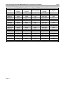
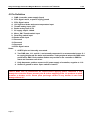
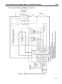
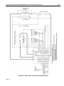
Kelly Full Bridge Permanent Magnet Motor Dc Controller User’s Manual V 3.3 Kelly Full Bridge Permanent Magnet Dc Motor Controller User’s Manual PM24101 PM24201 PM24301 PM36101 PM36201 PM48101 PM48201 PM48301 PM48401B PM48501B PM72101 PM72201 PM72301 PM72401B PM72501B PM12101H PM12201H Rev.3.3 Mar. 2011 Kelly Full Bridge Permanent Magnet Motor Dc Controller User’s Manual V 3.3 Contents Chapter 1 Introduction ......................................................................................... 2 1.1 Overview.................................................................................................. 2 Chapter 2 Main Features and Specifications ........................................................ 3 2.1 General functions..................................................................................... 3 2.2 Features .................................................................................................. 4 2.3 Specifications........................................................................................... 4 Chapter 3 Wiring and Installation ......................................................................... 6 3.1 Mounting the Controller ........................................................................... 6 3.2 Connections............................................................................................. 8 3.3 Installation Checklist .............................................................................. 12 Chapter 4 Maintenance ..................................................................................... 13 4.1 Cleaning ................................................................................................ 13 4.2 Configuration ......................................................................................... 13 Table 1: LED CODES ........................................................................................ 14 Contact Us: ........................................................................................................ 15 Page 1 Kelly Full Bridge Permanent Magnet Motor Dc Controller User’s Manual Chapter1 V 3.3 Introduction 1.1 Overview This manual introduces the Kelly PM motor controllers’ features, their installation and their maintenance. Read the manual carefully and thoroughly before using the controller. If you have any questions, please contact the support center of Kelly Controls, LLC. Kelly’s programmable motor controllers provide efficient, smooth and quiet controls for electric vehicles like golf carts, go-carts, electric motorcycles, scooters, forklifts and hybrid vehicles, as well as electric boat and industrial motor speed control. It uses high power MOSFET’s and, PWM to achieve efficiencies of up to 97% in most cases. A powerful microprocessor brings in comprehensive and precise control to the controllers. It also allows users to adjust parameters, conduct tests, and obtain diagnostic information quickly and easily. Kelly’s PM motor controller is full bridge or 4 quadrant controller. It provides fast and reliable electronic direction control. There is no arc, spark, or life limit on motor direction changes. Page 2 Kelly Full Bridge Permanent Magnet Motor Dc Controller User’s Manual V 3.3 Chapter2 Main Features and Specifications 2.1 General functions (1) Extended fault detection and protection. LED flashing code indicates fault sources. (2) Monitoring battery voltage. Stop driving if battery voltage is too high or too low. (3) Built-in current loop and over current protection. (4) Motor temperature input and protection. Configurable range. (5) Cutting back current at low temperature and high temperature to protect battery and controller. The current will ramp down quickly if controller temperature is higher than 90ﹾC, and shut down at 100ﹾC. Low temperature current ramping down usually starts at 0ﹾC. (6) Two RS232 ports. Both can be used for configuration. (7) Configurable and programmable with RS-232. Software upgradeable. Windows GUI provided. (8) Provide power supply (5V) for hall sensors and other sensors. (9)3 switch inputs: Default to throttle switch, brake switch and reversing switch. Closing to ground is to activate. (10) 3 analog inputs, 0-5V: Default to throttle input, brake input and motor temperature input. (11) PWMable reverse alarm output. (12) Main contactor driver. Cutting off the power if any fault is detected. (13) Current meter to display both drive and regen current. Save shunt. (14) Configurable boost switch. Output can arrive at the maximum current if the switch is enabled and turned on. (15) Configurable turbo switch. Limit max power to half if the switch is enabled and turned on. (16) Configurable max reverse power to half. (17) Enhanced regen brake function. Novel ABS technique provides powerful and smooth regen. (18) Configurable 12V brake signal input, in lieu of motor temperature sensor. (19) Optional joystick throttle. Single 0-5V signal for both forwarding and reversing. (20) Thermal overload detection and protection to safeguard the motor from over temperature, with recommended Silicon temperature sensors KTY83-122. (21) Using battery-powered. (22) Optional CAN bus. (23) Optional supply voltage 8V-30V. Page 3 Kelly Full Bridge Permanent Magnet Motor Dc Controller User’s Manual V 3.3 2.2 Features •Intelligence with powerful microprocessor. •Synchronous rectification, ultra low drop, and fast PWM to achieve very high efficiency. •Electronic reversing. •Voltage monitoring on voltage source 12V and 5V. •Current limit and torque control. Configurable torque mode and speed mode. •Low EMC. •LED fault code. •Battery protection: current cutback, warning and shutdown at configurable high and low battery voltage. •Rugged aluminum housing for maximum heat dissipation and harsh environment. •Rugged high current terminals, and rugged aviation connectors for small signal. •Thermal protection: current cut back, warning and shutdown on high temperature. •Configurable high pedal protection: Disable operation if power up with high throttle. •Brake switch is used to start regen. •Support three modes of regenerative braking: brake switch regen, release throttle regen, 0-5V analog signal variable regen. •Full Programmable with RS-232. Software upgradeable. Free Windows GUI software. •Standard PC/Laptop computer to do programming. No special tools needed. •User program provided. Easy to use. No cost to customers. •No adjustment. 2.3 Specifications •Frequency of Operation: 16.6kHz. •Standby Battery Current: < 0.5mA. •5V Sensor Supply Current: 40mA. •Controller supply voltage range, PWR, 18V to B+ (8V to 30V for Controllers rated equal 24V) •Supply Current,PWR,150mA. •Standard Throttle Input: 0-5 Volts(3-wire resistive pot), 1-4 Volts(hall active throttle). •Analog Brake and Throttle Input: 0-5 Volts. •Reverse Alarm, Main Contactor Coil Driver, Meter. •Full Power Temperature Range: 0ﹾC to 50ﹾC (controller case temperature). •Operating Temperature Range: -30ﹾC to 90ﹾC,100ﹾC shutdown(controller case temperature). •Motor Current Limit, 1 minutes: 100A-500A.depending on the model. •Motor Current Limit, continuous:40A-200A, depending on the model. •Max Battery Current :Configurable. Page 4 Kelly Full Bridge Permanent Magnet Motor Dc Controller User’s Manual Model PM24101 PM24201 PM24301 PM36101 PM36201 PM48101 PM48201 PM48301 PM48401B PM48501B PM72101 PM72201 PM72301 PM72401B PM72501B PM12101H PM12201H Page 5 Kelly Full Bridge Permanent Magnet DC Motor Controller 1 minute Continuous Voltage Rated Voltage Current Current Range 100A 40A 24V 12V-24V 200A 80A 24V 12V-24V 300A 120A 24V 12V-24V 100A 40A 36V 24V-36V 200A 80A 36V 24V-36V 100A 40A 48V 24V-48V 200A 80A 48V 24V-48V 300A 120A 48V 24V-48V 400A 160A 48V 24V-48V 500A 200A 48V 24V-48V 100A 40A 72V 24V-72V 200A 80A 72V 24V-72V 300A 120A 72V 24V-72V 400A 160A 72V 24V-72V 500A 200A 72V 24V-72V 100A 40A 120V 24V-120V 200A 80A 120V 24V-120V Female plugs of J1&J2 will be shipped for free. V 3.3 Regen Yes Yes Yes Yes Yes Yes Yes Yes Yes Yes Yes Yes Yes Yes Yes Yes Yes Kelly Full Bridge Permanent Magnet Motor Dc Controller User’s Manual V 3.3 Chapter 3 Wiring and Installation 3.1 Mounting the Controller The controller can be oriented in any position as clean and dry as possible, or shield with a cover to protect it from water and contaminants. To ensure full rated output power, the controller should be fastened to a clean, flat metal surface with four screws. Applying silicon gel or other thermal conductive material to contact surface will enhance thermal performance. Sufficient heat sink and air flow is required for high power application. The case outline and mounting holes’ dimensions are shown in Figure 1. Caution: • RUNAWAYS — Some conditions could cause the vehicle to run out of control. Disconnect the motor, or jack up the vehicle, and get the drive wheels off the ground before attempting any work on the motor control circuitry. • HIGH CURRENT ARCS — Electric vehicle batteries can supply very high power, and arcs can occur if they are short circuit. Always turn off the battery circuit before working on the motor control circuit. Wear safety glasses, and use properly insulated tools to prevent short circuit. Page 6 Kelly Full Bridge Permanent Magnet Motor Dc Controller User’s Manual Height: 62 millimeters Figure 1: mounting holes’ dimensions (dimensions in millimeters) Height: 62 millimeters Figure 2: PM-B mounting holes’ dimensions (dimensions in millimeters) Page 7 V 3.3 Kelly Full Bridge Permanent Magnet Motor Dc Controller User’s Manual V 3.3 3.2 Connections 3.2.1 Front Panel of PM Motor Controller: Four metal bars and two plugs (J1, J2) are provided for connecting to the battery, motor and control signals in the front of the controller shown as Figure 3. Figure 3: Front panel of PM motor controller B+: Battery positive B-: Battery negative M+: armature positive M-: armature negative Figure 4: The connecting diagram of J1 and J2 J1 Pin Definition 1- PWR: Controller power supply (output). The pin is Red LED for S/N less: 08XXXXXX. 2- Current meter <200mA. 3- Main contactor driver <2A. 4- Alarm: To drive reverse beeper. <200mA 5- RTN: Signal return 6- Green LED: Running indication 7- RTN: Signal return 8- RS232 receiver 9- RS232 transmitter 10- CAN bus high 11- CAN bus low 12- Reserved 13- RTN: Signal return, or power supply return 14- Red LED: Fault code. The pin is PWR for S/N less: 08XXXXXX. Page 8 Kelly Full Bridge Permanent Magnet Motor Dc Controller User’s Manual V 3.3 J2 Pin Definition 1- PWR: Controller power supply (input) 2- RTN: Signal return, or power supply ground 3- RTN: Signal return 4- 12V high-level brake and motor temperature input 5- Throttle analog input, 0-5V 6- Brake analog input, 0-5V 7- 5V supply output .<40mA 8- Micro_SW: Throttle switch input 9- Reversing switch input 10- Brake switch input 11- Reserved 12- Reserved 13- Reserved 14- RTN: Signal return Notes: 1. All RTN pins are internally connected. 2. Two PWR pins, J1-1 and J2-1, are internally connected. It’s recommended to use J1-1 to supply peripherals like alarm and contactor. Twist peripheral wires with PWR is the preferred for EMC. Recirculation diodes are provided in the controller to PWR for alarm and Contactor coil driver. 3. Kelly Ampmeter positive connect to 5V power supply of controller, negative to J1-2. 4. Switch to ground is active. Open switch is inactive. Caution: Make sure all connections are correct before applying power. Otherwise it may damage the controller! Please securely wire B- before applying power. It's preferred to place contactor or breaker on B+. Please place precharge resistor on any breaker! It can cause damage without it!!! Page 9 Kelly Full Bridge Permanent Magnet Motor Dc Controller User’s Manual V 3.3 3.2.2 Standard Wiring of PM Motor Controller Figure 5: PM motor controller standard wiring Page 10 Kelly Full Bridge Permanent Magnet Motor Dc Controller User’s Manual Figure 6: 120V motor controller standard wiring Page 11 V 3.3 Kelly Full Bridge Permanent Magnet Motor Dc Controller User’s Manual V 3.3 3.2.3 Communication Port A RS232 port of controller is provided to communicate with host computer for calibration and configuration. Figure 7: standard RS232 interface 3.3 Installation Checklist Before operating the vehicle, complete the following checkout procedures. Use LED code as a reference. The LED codes are listed in Table 1. Caution: • Put the vehicle up on blocks to get the drive wheels off the ground before beginning these tests. • Do not allow anyone to stand directly in front of or behind the vehicle during the checkout . • Make sure both the PWR switch and the brake are off. • Use well-insulated tools. • Make sure the wire is connected correctly. • Turn the PWR switch on. The LED should blink, then keep on when the controller operates normally. If this does not happen, check continuity of the PWR and controller ground. • The fault code will be detected automatically at restarting. • With the brake switch open, select a direction and operate the throttle. The motor should spin in the selected direction. Please verify wiring and voltage if it doesn’t operate. Also check fuse. The motor should run faster with increasing throttle. If not, refer to Table 1 LED code, and correct the fault according to the code. • Take the vehicle off the blocks and drive it in a clear area. It should have smooth acceleration and good top speed. Page 12 Kelly Full Bridge Permanent Magnet Motor Dc Controller User’s Manual Chapter 4 V 3.3 Maintenance There are no user-serviceable parts inside the controllers. Do not attempt to open the controller, or will void warranty. However, cleaning the controller exterior periodically should be necessary. The controller is inherently a high power device. When working with any battery powered vehicle, proper safety precautions should be taken. These include, but are not limited to, proper training, wearing eye protection, avoiding loose clothing and jewelry, and using insulated tools. 4.1 Cleaning Although the controller requires virtually no maintenance after properly installation, the following minor maintenance is recommended in certain applications. • Remove power by disconnecting the battery, starting with battery positive. • Discharge the capacitors in the controller by connecting a load (such as a contactor coil, resistor or a horn) across the controller’s B+ and B- terminals. • • Remove any dirt or corrosion from the bus bar area. The controller should be wiped down with a moist rag. Be sure it is dry before reconnecting the battery. Make sure the connections to the bus bars are tight. Use two wrenches for this task in order to avoid stressing the bus bars; the wrenches should be well insulated. 4.2 Configuration You can configure the controller with a host computer through RS232 or USB port. • Use straight through RS232 cable or Kelly Standard USB To RS232 Converter to connect the D9 connector to a host computer. Provide >18V (either J2 pin1 or J1 pin1) to PWR. Wire power supply return to any RTN pin. • Do not connect B+, throttle and so on. The controller may display fault code in some conditions, but it doesn't affect programming or configuration. Download and setup the configuration software: http://www.kellycontroller.com/support.php Caution: •Prohibit connecting controller's configuration software when the motor is running. •Configuration software will be regularly updated and published on the website. Please regularly uninstall the previous configuration software from your computer, download and install the new one. Page 13 Kelly Full Bridge Permanent Magnet Motor Dc Controller User’s Manual Table 1: V 3.3 LED CODES Green LED Code LED Code Green Off Green On Green and Red LED Keep On Explanation No power or not operating Normal operation Solution 1. Check if all wires are correct. 2. Check fuse and power supply. That’s great! You got solution! 1. Software is upgrading. 2. Supply voltage too low or battery too high 3. The controller is damaged. Please contact Kelly for warrantee. Red LED Code 1,2 ¤ ¤¤ Over voltage error 1. Battery voltage is higher than max operating voltage of the controller. Please check the battery voltage and configuration. 2. Over voltage at regeneration. Controller will cut back or stop regeneration. 3. Please note there could be 2% error with Overvoltage setting. 1,3 ¤ ¤¤¤ Low voltage error 1. The controller will attempt to clear the fault code automatically after 5 second if battery voltage returns to normal. 1,4 ¤ ¤¤¤¤ Over temperature warning 2,2 ¤¤ ¤¤ Internal voltage fault 2,3 ¤¤ ¤¤¤ Over temperature 2. Check the battery voltage. 3. Charge battery if necessary. 1. The controller temperature is over 90℃. The controller will cut back current in the case. Stop or reduce output to ensure the temperature fall. 2. Improve heat sink or airflow 1. Check if the B+ and PWR voltage are correct, refer to B- or RTN. Could be PWR voltage low. 2. Please check load on 5V supply. Could be high load on 5V. Incorrect pot wiring can load it heavily. 1. The controller is damaged. Please contact Kelly for warrantee. 1. When controller’s temperature is over 100℃. it will stop driving in order to protect itself. 2. Stop driving and wait for temperature fall. The controller will restart if temperature drops below 80℃. Page 14 Kelly Full Bridge Permanent Magnet Motor Dc Controller User’s Manual ¤¤¤¤ Throttle error at power up 2,4 ¤¤ 3,1 ¤¤¤ ¤ Frequent reset 3,2 ¤¤¤ ¤¤ Internal reset 3,3 ¤¤¤ ¤¤¤ 3,4 ¤¤¤ ¤¤¤¤ Throttle short or open circuit when using 1-4v hall sensor throttle Throttle isn’t zero when try to change direction 4,1 ¤¤¤¤ ¤ Over voltage at startup or regeneration 4, 3 ¤¤¤¤ ¤¤¤ Motor over temperature 1. The throttle signal is higher than configured dead zone at power-on. 2. The fault will disappear if restarts or releases throttle. 1. It can be caused by over current, bad motor, bad ground wiring or so. Reset caused by over current, high battery voltage or low supply voltage. It is normal if occurs occasionally. 1. Check whether the throttle is short or open up. 2. When the throttle is normal, restart will clear the error. The controller won’t change drive direction if throttle isn’t zero. Also it won’t change direction at high speed. The controller will wait throttle and speed close to zero before changing direction. The controller won’t drive motor if detects overvoltage at power up. It will cut back regen current or stop regen if detects overvoltage during regen. You may set overvoltage threshold with GUI. The max threshold is about 1.25 times of controller rated voltage. I.e. you may set threshold lower than 60V for 48V controller. 1.The motor temperature is higher than configured max temperature. Controller will shut down and wait for motor temperature dropping. 2.Can change the temperature setting with configuration program. The Red LED flashes once at power on, then keeps off for normal operation. “1, 2” means it flashed once, then flashes twice after 1 second. The time between two flashes is 0.5 second. The pause time between one error code and another error code is 2 second. Contact Us: Kelly Controls, LLC Page 15 V 3.3 Kelly Full Bridge Permanent Magnet Motor Dc Controller User’s Manual V 3.3 Home Page: http://www.kellycontroller.com E-mail: [email protected] Phone: (01) 224 637 5092 Page 16