1
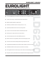
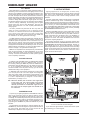
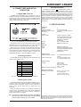
Version 1.0 July 2003 ENGLISH LD6230 EUROLIGHT Users Manual EUROLIGHT LD6230 IMPORTANT SAFETY INSTRUCTIONS DETAILED SAFETY INSTRUCTIONS: 1) Read these instructions. 2) Keep these instructions. 3) Heed all warnings. 4) Follow all instructions. CAUTION: WARNING: The units installation and initial operation must be done under the supervision of a qualified professional (see INSTALLATION INSTRUCTIONS). To reduce the risk of electric shock, do not remove the top cover (or the rear section). No user serviceable parts inside; refer servicing to qualified personnel. To reduce the risk of fire or electric shock, do not expose this appliance to rain and moisture. This symbol, wherever it appears, alerts you to the presence of uninsulated dangerous voltage inside the enclosurevoltage that may be sufficient to constitute a risk of shock. This symbol, wherever it appears, alerts you to important operating and maintenance instructions in the accompanying literature. Please read the manual. 5) Do not use this device near water. 6) Clean only with a dry cloth. 7) Do not block any ventilation openings. Install in accordance with the manufacturers instructions. 8) Do not install near any heat sources such as radiators, heat registers, stoves, or other apparatus (including amplifiers) that produce heat. 9) Do not defeat the safety purpose of the polarized or grounding-type plug. A polarized plug has two blades with one wider than the other. A grounding type plug has two blades and a third grounding prong. The wide blade or the third prong are provided for your safety. If the provided plug does not fit into your outlet, consult an electrician for replacement of the obsolete outlet. 10) Protect the power cord from being walked on or pinched particularly at plugs, extension cords, and the point at which they exit the unit. 11) Only use attachments/accessories specified by the manufacturer. 12) Use only with the cart, stand, tripod, bracket, or table specified by the manufacturer, or sold with the device. When a cart is used, use caution when moving the cart/ device combination to avoid injury from stumbling over it. 13) Unplug this device during lightning storms or when not used for long periods of time. 14) Refer all servicing to qualified service personnel. Servicing is required when the unit has been damaged in any way, such as power supply cord or plug is damaged, liquid has been spilled or objects have fallen into the device, the unit has been exposed to rain or moisture, does not operate normally, or has been dropped. 2 EUROLIGHT LD6230 EUROLIGHT Professional 6-channel DMX/analog controlled dimmer pack LD6230 s 6-channel DMX/analog controlled dimmer pack with up to 10 A output per channel s 3-phase mains supply (1 phase possible at lower output power) s DMX512 standard interface for digital control s Additional 8-pole DIN connector for analog control (0 - 10 V) s Adjustable preheat and limiter function to prolong bulb life s Precise curve function enables selection of different fade modes s Switch option for simple on/off control of each channel s Automatic digital input check to detect DMX signal errors s Manual mode for dimming capability without an external lighting console s Auto store function saves all settings after leaving configuration mode s 3-digit display and dedicated control LEDs for better indication in dark environment s HARTING® and CEE connection options (connectors not included) s Ultra-rugged construction ensures long life, even under the most demanding conditions s Designed in Germany. Manufactured under ISO9000 certified management system 3 EUROLIGHT LD6230 FOREWORD Dear customer, welcome to the team of BEHRINGER users, and thank you very much for expressing your confidence in us by purchasing the EUROLIGHT LD6230. Writing this foreword for you gives me great pleasure, because it represents the culmination of many months of hard work delivered by our engineering team to achieve a very ambitious goal: to present an outstanding dimmer pack whose flexibility makes it ideally suited for concert and theatre applications as well as film and TV productions. The task of designing the new LD6230 certainly meant a great deal of responsibility, which we assumed by focusing on you, the discerning user and musician. Meeting your expectations also meant a lot of work and night shifts. But it was fun, too. Developing a product usually brings a lot of people together, and what a great feeling it is when all who participated in such a project can be proud of what theyve achieved. It is our philosophy to share our enjoyment with you, because you are the most important member of the BEHRINGER team. With your highly competent suggestions for new products youve made a significant contribution to shaping our company and making it successful. In return, we guarantee you uncompromising quality as well as excellent technical and audio properties at an extremely reasonable price. All of this will enable you to give free rein to your creativity without being hampered by budget constraints. We are often asked how we manage to produce such highquality devices at such unbelievably low prices. The answer is quite simple: its you, our customers! Many satisfied customers mean large sales volumes enabling us to get better purchasing terms for components, etc. Isnt it only fair to pass this benefit on to you? Because we know that your success is our success too! I would like to thank all of you who have made the EUROLIGHT LD6230 possible. You have all made your own personal contributions, from the developers to the many other employees at this company, and to you, the BEHRINGER user. My friends, its been worth the effort! Thank you very much, Uli Behringer 4 TABLE OF CONTENTS 1. INTRODUCTION ......................................................... 5 1.1 Before you get started ................................................... 5 1.1.1 Shipment ............................................................... 5 1.1.2 Initial operation ...................................................... 5 1.1.3 Rack installation .................................................... 5 1.1.4 Warranty .............................................................. 5 1.2 The users manual .......................................................... 5 2. CONTROL ELEMENTS ............................................... 6 2.1 Configuration mode ........................................................ 7 2.1.1 ADDRESS ............................................................. 7 2.1.2 ASSIGN ................................................................ 7 2.1.3 PREHEAT .............................................................. 7 2.1.4 LIMITER ................................................................. 7 2.1.5 CURVE .................................................................. 7 2.2 DMX mode ....................................................................... 7 2.2.1 DMX512 ................................................................ 8 2.3 ANALOG mode ............................................................... 8 2.4 MANUAL mode ............................................................... 8 3. APPLICATIONS .......................................................... 8 4. INSTALLATION AND INITIAL OPERATION ................. 9 4.1 4.2 4.3 4.4 Digital DMX connector .................................................... 9 Analog connector ........................................................... 9 EEP (eprom check) ......................................................... 9 Phase allocation ............................................................. 9 5. SPECIFICATIONS ....................................................... 9 6. WARRANTY .............................................................. 10 EUROLIGHT LD6230 1.1.3 Rack installation 1. INTRODUCTION As a BEHRINGER EUROLIGHT LD6230 owner, you have a highend dimmer pack at your hands. It was designed to answer to the high demands of lighting professionals working in television, theatres and live events, and is therefore universally applicable. The EUROLIGHT LD6230 provides all necessary features for controlling your light show, yet it is clearly laid out and easy to use. It gives you the choice between analog and digital DMX control. Comprehensive LEDs let you easily detect signal problems so you can effortlessly eliminate them as soon as they occur. + + The following users manual is intended to familiarize you with the units control elements, so that you can master all the functions. After having thoroughly read the users manual, store it at a safe place for future reference. INSTALLATION INSTRUCTIONS supplement the users manual and are included in the shipment. A qualified professional needs to be present during the units installation and initial operation. More information about this topic is covered under INSTALLATION INSTRUCTIONS. The LD6230 requires two height units (2 HU) when installed in a 19-inch rack. Please make sure to leave an extra 4 inches (10 cm) of space behind the unit for wiring. Please use M6 machine screws and nuts to install your LD6230 into a rack. 1.1.4 Warranty Please take a few minutes and send us the completely filled out warranty card within 14 days of the date of purchase. You may also register online at www.behringer.com. The serial number of your EUROLIGHT LD6230 ( ) needed for registration is located at the rear panel of the unit. Failure to register your product may void future warranty claims. 1.2 The users manual The users manual is designed to give you both an overview of the controls, as well as detailed information on how to use them. In order to help you understand the links between the controls, we have arranged them in groups according to their function. If you need to know more about specific issues, please visit our website at http://www.behringer.com. 1.1 Before you get started 1.1.1 Shipment The LD6230 was carefully packed at the assembly plant to assure secure transport. Should the condition of the cardboard box suggest that damage may have occurred please inspect the unit immediately and look for physical indications of damage. + Damaged units should NEVER be sent directly to us. Please inform the dealer from whom you acquired the unit immediately as well as the transportation company from which you took delivery. Otherwise, all claims for replacement/repair may be rendered invalid. 1.1.2 Initial operation Please make sure the unit is provided with sufficient ventilation, and never place the EUROLIGHT on top of an amplifier or in the vicinity of a heater to avoid the risk of overheating. + + + Please make sure that the unit is grounded at all times. For your own protection, you should never tamper with the grounding of the cable or the unit itself. To avoid damage to your equipment, always make sure your dimmer pack is disconnected from the mains before you connect or disconnect spotlights or other lighting paraphernalia. Make sure that only sufficiently qualified persons install and operate your LD6230. To avoid damage or altering of its performance through electrostatic discharge, make sure that all people handling the LD6230 are properly grounded both during and after the installation. 1. INTRODUCTION 5 EUROLIGHT LD6230 2. CONTROL ELEMENTS Various LD6230 control elements are described in this chapter. All controls and connectors are described in detail, and you also get useful advice on how to use them in different applications. Fig. 2.1: EUROLIGHT LD6230s front panel Ventilation openings are located on the front panel. Their position at the front assures that hot air does not enter the inside of your rack, causing equipment failure or damage. + To ensure that your dimmer pack runs smoothly even under full load, you have to make sure that there is enough distance to other heat-emitting equipment. There is an automated fuse for each of the six dimmer circles. These fuses engage in the event of overload or short circuit. Use the CHANNEL key to shift between the six dimmer channels. When used in combination with the CONFIG key (see ), you can select different operating modes (DMX, ANALOG and MANUAL). Use the UP and DOWN keys to navigate through individual menus. The CONFIG key is used to activate the configuration mode (see ch. 2.1) and to select individual menus. When used in combination with the CHANNEL key (see ), you can select different operating modes. The LEDs to the left of the display have two purposes: supply phase status indication (L1, L2 und L3) and indication of the operating mode you selected (DMX, ANALOG and MANUAL). The 3-digit DISPLAY shows the values to be edited. The LEDs to the right of the display relate to the individual menus in the configuration mode. Depending on the selected function, the corresponding LED lights up. Fig. 2.2: EUROLIGHT LD6230s rear panel When your LD6230 works in DMX mode, use the 5-pole DMX512 IN-XLR connector to connect DMX512 control signals (see ch. 2.2 DMX mode and ch. 4.1 Digital DMX connector). You can relay the DMX control signal to additional dimmer packs by using the 5-pole DMX512 OUT XLR connector. If the dimmer is at the terminal end of a DMX chain, place a terminator at the DMX output of the dimmer pack to avoid signal bounce (use a terminator with the resistance of 120 Ω between pins 2 and 3). You can connect an analog 0 - 10 V control signal to the 8-pole ANALOG IN DIN connector (see ch. 2.3 ANALOG mode and ch. 4.2 Analog connector). 6 This is the cable slot for connecting your lighting equipment (see INSTALLATION INSTRUCTIONS). This is the cable slot for the power supply (see INSTALLATION INSTRUCTIONS). The cooling fan is located here. SERIAL NUMBER. Please take a few minutes and send us the completely filled out warranty card within 14 days of the date of purchase. Otherwise, warranty claims may be rendered invalid. You may also register online at www.behringer.com. 2. CONTROL ELEMENTS EUROLIGHT LD6230 2.1 Configuration mode 2.1.4 LIMITER The important pre adjustments necessary for running the dimmer pack are done in the configuration mode. Keeping the CONFIG key pressed for roughly two seconds gets you into the configuration menu. Once you are in the configuration mode, keep using the CONFIG key to navigate through individual functions, which are indicated with their respective LEDs located to the right of the display. To get out of the configuration mode, keep the CONFIG pressed again for roughly two seconds. When you press the CONFIG key once again, you get to the LIMITER menu (the LIMITER LED lights up). Use the CONFIG key to navigate through all six channels. Here you can set the upper limit for the control signal of each individual channel. Set the threshold value (0 to 99) by using the UP and DOWN keys. The LIMITER function too prolongs the life of your light equipment. Limiting the upper range of control voltage protects from voltage oscillations and overdrive. The LIMITER function cannot be used in SWITCH mode (see ch. 2.1.5). + All adjustments made in configuration mode are automatically stored when you exit, and remain stored even when you power the LD6230 on or off. 2.1.1 ADDRESS As soon as you get to the configuration mode, the ADDRESS LED lights up. In this menu, you assign DMX basic channels (1 to 507) to the six dimmer channels. This address determines the DMX channel at which control commands are executed. Since you are dealing with a 6-channel dimmer, a maximum of six consecutive DMX channels can be interpreted as control signals, depending on the assignments in the ASSIGN menu (see ch. 2.1.2). If the start address value is 001, then the dimmer reacts to the first six channels of the DMX data stream. If you, for example, set the start address value to 024, then the dimmer reacts to the channels 024 to 029 correspondingly. If several units use the same DMX address, then they also receive the same control commands. To select the desired DMX channels, use the UP and DOWN keys. When you keep one of these keys pressed while tapping the other one simultaneously, this lets you navigate through the channels in increments of 10 channels at a time. 2.1.2 ASSIGN When you press the CONFIG key once again, you get to the ASSIGN menu (ASSIGN LED lights up). In this menu you can make four different input channel/dimmer channel assignments. Possible configurations: 1-6: All six outputs are dependent on the setting of channel 1. 2-3: Outputs 1-3 are dependent on the setting of channel 1, and outputs 4-6 are dependent on the setting of channel 2. 3-2: Outputs 1 and 2 are dependent on the setting of channel 1, outputs 3 and 4 are dependent on the setting of channel 2, and outputs 5 and 6 are dependent on the setting of channel 3. 6-1: All six outputs are separately dependent on the respective six channels (1-6). If you select one of the first three configuration options, you can for example form headlight groups that reproduce the same identical program since they are controlled through just one channel. After you address DMX channels and assign input and dimmer channels, you should check if each dimmer circle reacts to the desired DMX control signal by moving the corresponding faders on the lighting console. 2.1.3 PREHEAT When you press the CONFIG key once again, you get to the PREHEAT menu (the PREHEAT LED lights up). Use the UP and DOWN keys to enter the preheat value (OFF to 99). This preheat value is then continuously run to the headlights, thus lowering the start-up current requirement and prolonging filament life. The preheat value you enter is valid for all six channels. However, the PREHEAT function cannot be used in switch mode (see ch. 2.1.5). 2.1.5 CURVE When you press the CONFIG key once again, you get to the CURVE menu (the CURVE LED lights up). There are four possible ways to set up the transmission characteristic of your dimmer pack. You can determine how control voltage (i.e. fader movement on the mixing console) is transmitted to the lighting equipment. Step through the six channels indicated on the lefthand digit on the display by pressing the CONFIG key. Define the transmission characteristic for each channel separately by using the UP key. LINEAR (L): This transmission characteristic linearly increases or decreases control voltages in all segments of fader movement. When you move a fader on the lighting console, the headlight intensity changes directly proportionate to the fader movement. EXPONENTIAL (o1): In this case, the transmission curve is irregular. When you move the fader on the lighting console uniformly upwards, the voltage in the lower third of the faders range of movement increases linearly, whereas the transmission characteristic beyond the first third of the faders range of motion becomes more pronouncedly (exponentially) progressive with each increment of fader motion. LOGARITHMIC (o2): This transmission characteristic is also irregular. In the upper third of the faders range of motion the voltage changes linearly, whereas the transmission characteristic in the lower two thirds gets more pronouncedly degressive with each increment of fader motion. The logarithmic transmission curve is the opposite of the exponential curve. SWITCH OPERATION (S): In this mode you can use the dimmer circle as a switch. This way, you can use your LD6230 to control fog machines, motors and various other effects. When the control voltage reaches 50% or more of a previously specified value, the channel is switched on. When the control voltage falls below 50%, the channel is switched off again. LIMITER and PREHEAT functions cannot be used in this mode. + Transmission curves can be separately adjusted for each individual channel on the EUROLIGHT LD6230. 2.2 DMX mode Your LD6230 is automatically in DMX mode as soon as the power is up (DMX LED lights up). Navigate through different modes by using the CHANNEL key while simultaneously pressing the CONFIG key. Your LD6230 receives the DMX signal via the DMX512 IN connector, and this signal can be forwarded to additional dimmer packs using the DMX512 OUT connector in order to process additional channels. DMX512 IN and DMX512 OUT are 5-pole XLR connectors and are located on the rear panel. 2. CONTROL ELEMENTS 7 EUROLIGHT LD6230 2.2.1 DMX512 Data transmission in the field of lighting equipment refers to transmitting control information from the lighting console via the dimmer to the headlights, scanners and similar equipment. This process takes place by using the digital DMX512 control signal that was developed at the USITT (United States Institute for Theatre Technology). Information is no longer represented through analog voltage values; instead, digital data sets are used. In contrast to analog data transmission, digital signals can simply be patched together: each piece of information has an address to which it belongs. Additionally, the following goes for digital signals: when they arrive at their destination, they have the correct value since there is no loss of quality associated with analog signals. Of course, problems may arise here as well. Very often, the reason for faulty transmissions lies in deploying wrong connectors or connectors other than those prescribed by the norm. Using wrong cables also may lead to faulty data transmission. We therefore only recommend using cables that are intended for use with digital audio technology. The DMX standard contains 512 digital light channels that are controlled using a common data cable. However, a maximum of 32 different pieces of equipment can be connected to any one cable since the cable at some point becomes overburdened (due to shared controlling of all end equipment). Still, each piece of equipment can evaluate as much data as you wish. To connect additional pieces of equipment, you need a so-called splitter or a booster to amplify or to regenerate the DMX signal. DMX512 is a compatible norm and requires only one data cable since all signal recipients are freely addressable, so you avoid having cable salad issues. Once all pieces of equipment are correctly connected and addressed, a DMX system typically works completely trouble-free. 3. APPLICATIONS Lighting equipment is an integral part of almost every performance event and venue. Be it concerts, theatre or musical acts, clubs or even presentations and exhibits, they all benefit from good visuals in order to leave a lasting impression on the audience. In general, lighting either creates a certain feeling or emphasizes the mood created through music or dramaturgic composition. Creating a lighting setup is a demanding and creative endeavour, since it is much more than merely making a set of lights go on and off. To do this, you need a dependable, multi-functional set of tools. The EUROLIGHT LD6230 offers a maximum on functionality and is the perfect expansion for a lighting console, preferably the BEHRINGER EUROLIGHT LC2412. Thanks to digital DMX controlling, using multiple dimmer packs lets you implement demanding lighting setups, since you can control up to 32 components with only one DMX connection. These components dont necessarily have to be headlights; in switch mode, you can also control fog machines, pyrotechnic equipment or motors. This makes the LD6230 much more than just a piece of lighting equipment. The following illustration shows a connection example with two EUROLIGHT LD6230s, a BEHRINGER EUROLIGHT LC2412 and BEHRINGER ULTRAPAR UP1000 headlights, whereby 12 light channels can be run. The first dimmer pack is controlled with the digital DMX control signal, the second one with an analog signal. If both dimmer packs are controlled with the DMX control signal, the second dimmer pack needs to receive the control signal via the first dimmer pack: 2.3 ANALOG mode In addition to the digital DMX mode, your EUROLIGHT LD6230 dimmer pack also lets you work in ANALOG mode. You get to this mode by pressing the MODE key while the CONFIG key is pressed (the ANALOG LED lights up). The analog control signal (0 - 10 V) is transfered to the dimmer pack via an 8-pole DIN connector located on the rear panel. This way, you can use the LD6230 with analog control equipment. In ANALOG mode, each dimmer channel has a control cable (or a core pair) of its own. The control signal runs through this cable. The output voltage of the dimmer is proportionate to the control cable signal. As a rule, 0% is represented by a voltage of 0 V, 50% is represented by a voltage of 5 V and 100% is represented by a voltage of 10 V. + When the dimmer pack receives a zero signal level at the input end, the output signal level should correspondingly be at its minimum. When the dimmer pack receives a maximum signal level at the input end, the output signal level should be at its maximum. 2.4 MANUAL mode To power up your lighting equipment, the EUROLIGHT dimmer pack can be used even without an external lighting console when in MANUAL mode (MANUAL LED lights up). In this mode, all settings are automatically saved every two seconds and can be recalled even after powering the LD6230 off and then on again. As with other operating modes, you get to MANUAL mode by pressing the CHANNEL key while the CONFIG key is kept pressed. The left display digit indicates the channel selected with the CHANNEL key. The next two digits to its right indicate the level of the control signal, with values from 0 to 99. Use the UP and DOWN keys to adjust the control signal value. 8 Fig. 3.1: Connection example with the EUROLIGHT LC2412 and the ULTRAPAR UP1000 headlights If you need more light channels, connect extra dimmer packs for processing your control signals. 3. APPLICATIONS EUROLIGHT LD6230 4. CONNECTORS AND INITIAL OPERATION 4.1 Digital DMX connector The DMX512 IN and DMX512 OUT connectors are made in accordance with the international DMX512 standard. 5-pole XLR connectors are used, whereby controllers and DMX senders feature female connectors, while receiver equipment such as dimmer packs feature male connectors. 4.4 Phase allocation The LEDs L1, L2 and L3 ( ) indicate phase condition. L1 refers to channels 1 and 2, L2 refers to channels 3 and 4, and L3 refers to channels 5 and 6. The LEDs show if correct voltage is applied to your EUROLIGHT LD6230. If the voltage is not correct (i.e. too high or too low), the corresponding LED(s) begin to blink. Since the dimmers circuitry is powered by all three phases, the dimmer remains functioning even if two out of three phases malfunction. However, to guarantee trouble-free operation, always attempt to correct phase problems as soon as they are discovered. 5. SPECIFICATIONS Channels Number Load per channel Maximal load per channel Frequency Inputs Power supply Fig. 4.1: Pin assignment of a 5-pole XLR connector You should stick to the pin assignment shown in above illustration even when two reserve pins 4 and 5 are used for a second connection (a separate sender and receiver unit). Often, 3-pole XLR connectors are also used for transmitting digital control signals, since these connectors simplify using the wiring already at the users disposal and are also less expensive than 5-pole connectors. However, these connectors are substandard and may not carry the DMX512 insignia. 4.2 Analog connector An 8-pole DIN connector is used as the input connection for an analog control signal (0-10 V). 3,1 &+$11(/ 1 1 2 2 3 3 4 4 5 5 6 6 7 Power supply 8 Ground Analog Digital Outputs Digital Load System fuses Load securing per channel Control section fuse 6 0.2 A min./10 A max. 10 A using a 3-phase connector 50/60 Hz 3-phase connector, internal terminal block/PG cable screw joint, CEE connector (optional installation by qualified professional) 0 to +10 V via 8 pin DIN DMX512 via XLR 5 pin DMX512 via XLR 5 pin Internal terminal block/PG cable screw joint, HARTING® (optional installation by qualified professional) 10 A cable protection switch (type C) 3 x T 100 mA H/250 V (EU) 3 x T 160 mA H/250 V (UL) Power supply Voltage USA/Canada 120 V~, 60 Hz Europe/U.K./Australia 240 V~, 50 Hz Maximum power consumption 3 x 20 A Dimensions/Weight Dimensions (H x W x D) Weight approx. 3 1/3" (84.3 mm) x 19" (482.6 mm) x 15 9/10" (403.8 mm) approx. 20.3 lbs. (9.2 kg) Tab. 4.1: Pin assignment of an 8-pole DIN connector 4.3 EEP (eprom check) An eprom (Erasable Programmable Read Only Memory) is an electronic device that contains programs or data needed to operate a piece of equipment. Once you burn data onto an eprom, it cant get lost, even when you power down your equipment. During the power-up procedure of your LD6230, the eprom is checked, that is, the LD6230 looks for false values (plausibility control). If irregularities occur during the eprom initialisation, factory default values are loaded. + To erase the contents of the eprom and load factory defaults, keep both middle keys (UP and DOWN) pressed while powering up your LD6230. BEHRINGER continuously strives to assure the highest quality standards possible. Required modifications may be implemented without prior notice. Technical data and the appearance of the unit may deviate from the above values and/or illustrations. 5. SPECIFICATIONS 9 EUROLIGHT LD6230 6. WARRANTY § 1 WARRANTY CARD/ONLINE REGISTRATION To be protected by the extended warranty, the buyer must complete and return the enclosed warranty card within 14 days of the date of purchase to BEHRINGER Spezielle Studiotechnik GmbH, in accordance with the conditions stipulated in § 3. Failure to return the card in due time (date as per postmark) will void any extended warranty claims. Based on the conditions herein, the buyer may also choose to use the online registration option via the Internet (www.behringer.com or www.behringer.de). § 2 WARRANTY 1. BEHRINGER (BEHRINGER Spezielle Studiotechnik GmbH including all BEHRINGER subsidiaries listed on the enclosed page, except BEHRINGER Japan) warrants the mechanical and electronic components of this product to be free of defects in material and workmanship for a period of one (1) year* from the original date of purchase, in accordance with the warranty regulations described below. If the product shows any defects within the specified warranty period that are not excluded from this warranty as described under § 3 and 4, BEHRINGER shall, at its discretion, either replace or repair the product using suitable new or reconditioned parts. In the case that other parts are used which constitute an improvement, BEHRINGER may, at its discretion, charge the customer for the additional cost of these parts. 2. If the warranty claim proves to be justified, the product will be returned to the user freight prepaid. 3. Warranty claims other than those indicated above are expressly excluded. § 3 RETURN AUTHORIZATION NUMBER 1. To obtain warranty service, the buyer (or his authorized dealer) must call BEHRINGER (see enclosed list) during normal business hours BEFORE returning the product. All inquiries must be accompanied by a description of the problem. BEHRINGER will then issue a return authorization number. 2. Subsequently, the product must be returned in its original shipping carton, together with the return authorization number to the address indicated by BEHRINGER. 3. Shipments without freight prepaid will not be accepted. § 4 WARRANTY REGULATIONS 1. Warranty services will be furnished only if the product is accompanied by a copy of the original retail dealers invoice. Any product deemed eligible for repair or replacement by BEHRINGER under the terms of this warranty will be repaired or replaced within 30 days of receipt of the product at BEHRINGER. 2. If the product needs to be modified or adapted in order to comply with applicable technical or safety standards on a national or local level, in any country which is not the country for which the product was originally developed and manufactured, this modification/adaptation shall not be considered a defect in materials or workmanship. The warranty does not cover any such modification/adaptation, irrespective of whether it was carried out properly or not. Under the terms of this warranty, BEHRINGER shall not be held responsible for any cost resulting from such a modification/adaptation. 3. Free inspections and maintenance/repair work are expressly excluded from this warranty, in particular, if caused by improper handling of the product by the user. This also applies to defects caused by normal wear and tear, in particular, of faders, potentiometers, keys/buttons and similar parts. 4. Damages/defects caused by the following conditions are not covered by this warranty: s improper handling, neglect or failure to operate the unit in compliance with the instructions given in BEHRINGER user or service manuals. s connection or operation of the unit in any way that does not comply with the technical or safety regulations applicable in the country where the product is used. s damages/defects caused by force majeure or any other condition that is beyond the control of BEHRINGER. 5. Any repair or opening of the unit carried out by unauthorized personnel (user included) will void the warranty. 6. If an inspection of the product by BEHRINGER shows that the defect in question is not covered by the warranty, the inspection costs are payable by the customer. 7. Products which do not meet the terms of this warranty will be repaired exclusively at the buyers expense. BEHRINGER will inform the buyer of any such circumstance. If the buyer fails to submit a written repair order within 6 weeks after notification, BEHRINGER will return the unit C.O.D. with a separate invoice for freight and packing. Such costs will also be invoiced separately when the buyer has sent in a written repair order. § 5 WARRANTY TRANSFERABILITY This warranty is extended exclusively to the original buyer (customer of retail dealer) and is not transferable to anyone who may subsequently purchase this product. No other person (retail dealer, etc.) shall be entitled to give any warranty promise on behalf of BEHRINGER. § 6 CLAIM FOR DAMAGES Failure of BEHRINGER to provide proper warranty service shall not entitle the buyer to claim (consequential) damages. In no event shall the liability of BEHRINGER exceed the invoiced value of the product. § 7 OTHER WARRANTY RIGHTS AND NATIONAL LAW 1. This warranty does not exclude or limit the buyers statutory rights provided by national law, in particular, any such rights against the seller that arise from a legally effective purchase contract. 2. The warranty regulations mentioned herein are applicable unless they constitute an infringement of national warranty law. * Customers in the European Union please contact BEHRINGER Germany Support for further details. The information contained in this manual is subject to change without notice. No part of this manual may be reproduced or transmitted in any form or by any means, electronic or mechanical, including photocopying and recording of any kind, for any purpose, without the express written permission of BEHRINGER Spezielle Studiotechnik GmbH. BEHRINGER is a registered trademark. HARTING® is a registered trademark of the respective owner, which is in no way associated or affiliated with BEHRINGER. ALL RIGHTS RESERVED. © 2003 BEHRINGER Spezielle Studiotechnik GmbH. BEHRINGER Spezielle Studiotechnik GmbH, Hanns-Martin-Schleyer-Str. 36-38, 47877 Willich-Münchheide II, Germany Tel. +49 2154 9206 0, Fax +49 2154 9206 4903 10 6. WARRANTY