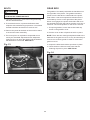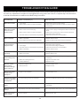
1
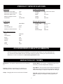
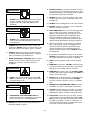
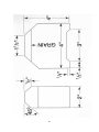
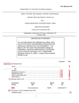
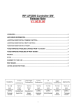
R
16” INDUSTRIAL PLANER
STEEL CITY TOOL WORKS
VER. 10.08
Model No.
40260H With
Helical Cutterhead
Manual Part No. SC75003
R
THANK YOU fo r pu rch as ing yo ur ne w St ee
l Ci ty
tes ted , an d ins pe cte d
d,
ne
sig
de
en
be
s
ha
r
ne
pla
is
Th
Pl an er.
he n pr op erl y us ed an d
wi th yo u, the cu sto me r, in mi nd . W
ide yo u wi th ye ars of
ma int ain ed , yo ur pla ne r wi ll pr ov
it is ba ck ed by on e of the
tro ub le fre e se rv ice , wh ich is wh y
bu sin es s.
lon ge st ma ch ine ry wa rra nti es in the
od uc ts in the St ee l
pr
ny
ma
of
e
on
t
jus
is
r
ne
pla
is
Th
ine ry an d is pr oo f of
ch
ma
ing
rk
wo
od
wo
of
ily
fam
s
Ci ty'
r sa tis fac tio n.
ou r co mm itm en t to tot al cu sto me
fo r ex ce lle nc e ea ch an d
At St ee l Ci ty we co nti nu e to str ive
yo u, ou r cu sto me r. Fo r
ev ery da y an d va lue the op ini on of
ee l Ci ty To ol Wor ks ,
co mm en ts ab ou t yo ur pla ne r or St
elc ity to olw or ks .co m
ple as e vis it ou r we b sit e at ww w. ste
2
TABLE OF CONTENTS
INTRODUCTION
SECTION 1
Warranty ......................................................................................................................................4
SECTION 2
Product Specifications ..................................................................................................................7
SECTION 3
Accessories and Attachments .......................................................................................................7
SECTION 4
Definition of Terms.........................................................................................................................7
SECTION 5
Feature Identification ....................................................................................................................8
SECTION 6
General Safety..............................................................................................................................9
SECTION 7
Product Safety ............................................................................................................................11
SECTION 8
Electrical Requirements...............................................................................................................12
SECTION 9
Grounding Instructions ................................................................................................................13
SECTION 10 Unpacking & Inventory.................................................................................................................14
SECTION 11 Assembly ...................................................................................................................................16
SECTION 12 Adjustments ...............................................................................................................................19
SECTION 13 Operations .................................................................................................................................27
SECTION 14 Maintenance ..............................................................................................................................29
SECTION 15 Troubleshooting Guide................................................................................................................30
SECTION 16 Parts List...................................................................................................................................33
INTRODUCTION
This user manual is intended for use by anyone working with this machine. It should be kept available
for immediate reference so that all operations can be performed with maximum efficiency and safety.
Do not attempt to perform maintenance or operate this machine until you have read and understand
the information contained in this manual.
This Planer is designed to process wood only. Any other use is forbidden. This machine is not to be
modified for any reasons.
The drawings, illustrations, photographs, and specifications in this user manual represent your
machine at time of print. However, changes may be made to your machine or this manual at any time
with no obligation to Steel City Tool Works.
3
WARRANTY
2 YEAR LIMITED WARRANTY
Steel City Tool Works, LLC (SCTW) warrants this SCTW machinery to be free of defects in workmanship and materials for a period
of 2 years from the date of the original retail purchase by the original owner for domestic use. Granite components are warranted for
2 years based on normal use and is void if non SCTW accessories are used that cause the break or chip. Customer must advise
SCTW within 30 days for any damage or defect found upon receipt of the product to qualify for the warranty on granite.
The warranty does not cover any product used for professional or commercial production purpose nor for industrial or educational
applications. Such cases are covered by our 1 year Limited Warranty with the Conditions and Exceptions listed below.
Conditions and exception:
Warranty applies to the original buyer only and may not be transferred. Original proof of purchase is required.
Warranty does not include failures, breakage or defects deemed after inspection by an Authorized Service Center, (ASC) or agent of,
have been directly or indirectly caused by or resulting from improper use, lack of or improper maintenance, misuse or abuse,
negligence, accidents, damage in handling or transport, or normal wear and tear of any part or component.
Additionally, warranty is void if repairs or alterations are made to the machine by an unauthorized service center without the direct
consent of SCTW
Consumables such as blades, knives, bits and sandpaper are not covered.
Wear items such as drive belt, bearings, switch, are covered for 1 year.
To file a claim of warranty or to find a service center, call toll free 877-724-8665 or email [email protected] and
you must be able to present the original or photo copy of the sales receipt including the serial number from the machine and/or carton.
SCTW will inspect, repair or replace, at its expense and its option, any part that has proven to be defective in workmanship or
material, provided that the customer returns the product prepaid to a designated ASC and provides SCTW with a reasonable
opportunity to verify the alleged defect by inspection. SCTW will return the product or replacement at our expense unless it is
determined by us that there is no defect or that the defect resulted from causes not within the scope of our warranty in which case we
will, at your direction, dispose of or return the product. In the event you choose to have the product returned, you will be responsible
for the handling and shipping costs of the return.
SCTW furnishes the above warranties in lieu of all other warranties, express or implied. SCTW shall not be liable for any special,
indirect, incidental, punitive or consequential damages, including without limitation loss of profits arising from or related to the
warranty, the breach of any agreement or warranty, or the operation or use of its machinery, including without limitation damages
arising from damage to fixtures, tools, equipment, parts or materials, direct or indirect loss caused by and other part, loss of revenue
or profits, financing or interest charges, and claims by and third person, whether or not notice of such possible damages has been
given to SCTW. Damages or any kind for any delay by or failure of SCTW to perform its obligations under this agreement or claims
made a subject of a legal proceeding against SCTW more than one (1) year after such cause of action first arose.
The validity, construction and performance of this Warranty and any sale of machinery by SCTW shall be governed by the law of the
Commonwealth of Pennsylvania, without regard to conflicts of law’s provisions of any jurisdiction. Any action related in any way to
any alleged or actual offer, acceptance or sale by SCTW or any claim related to the performance of and agreement including without
limitation this Warranty, shall take place in the federal or state courts in Allegheny County, Pennsylvania.
Warranty registration card must be submitted to SCTW for purpose of proof within 90 days of purchase with a copy of the sales
receipt. Failure to do so will, revert the 2 year warranty to 1 year as in the terms stated above. This registration is also needed to
facilitate contact in case of a safety recall.
This warranty gives you specific legal rights and you may have other rights which vary in certain States or Provinces.
Note to user
This instruction manual is meant to serve as a guide only. Specification and references are subject to change without prior notice.
Check the website www.steelcitytoolworks.com for updated manuals with reference to the VER# located on the front page.
LIMITED WARRANTY – ACCU-SHOP line of bench top tools
Steel City Tool Works, LLC (SCTW) warrants this SCTW ACCU-SHOP machinery to be free of defects in workmanship and materials
for a period of 2 years from the date of the original retail purchase by the original owner for domestic use.
Consumables such as blades, knives, bits and sandpaper are not covered.
Wear items such as drive belt, bearings, switch, are covered for 1 year.
The warranty does not cover any product used for professional or commercial production purpose nor for industrial or educational
applications. Such cases are covered by our 30 days Limited Warranty with the Conditions and Exceptions listed previously.
4
WARRANTY CARD
Name ________________________________________________
Street _______________________________________________
Apt. No. ______________________________________________
City _________________________ State ______ Zip __________
Phone Number_________________________________________
E-Mail ________________________________________________
The following information is given on a voluntary basis
and is strictly confidential.
2.
Where did you purchase your STEEL CITY machine?
Store: ____________________________________________
City:______________________________________________
CUT HERE
3.
4.
5.
Which of the following magazines do you subscribe to?
___ American Woodworker
___ American How-To
___ Family Handyman
___ Fine Homebuilding
___ Journal of Light Construction
___ Popular Mechanics
___ Fine Woodworking
___ Old House Journal
___ Popular Science
___ Popular Woodworking
___ Today’s Homeowner
___ WOOD
___ WOODEN Boat
___ Woodsmith
___ Woodcraft
___ Woodshop News
___ Woodwork
___ Woodworker
___ Workbench
___ Woodworker’s Journal
Other_________________
6.
7.
___ Air Compressor
___ Drill Press
___ Dust Collection
___ Band Saw
___ Drum Sander
___ Horizontal Boring Machine
___
___
___
___
___
___
___
___
Jointer
Mortiser
Planer
Radial Arm Saw
Lathe
Panel Saw
Power Feeder
Shaper
___ Belt Sander
___ Drill Press
___ Belt / Disc Sander
___ Band Saw
___ Grinder
___ Mini Lathe
___ Mini Jointer
___ Scroll Saw
___ Spindle / Belt Sander
Other______________________
12. Which portable / hand held power tools do you own?
Check all that apply.
___ Belt Sander
___ Biscuit Jointer
___ Dust Collector
___ Circular Saw
___ Detail Sander
___ Miter Saw
___ Drill / Driver
___ Orbital Sander
___ Palm Sander
___ Saber Saw
___ Portable Thickness Planer
___ Reciprocating Saw
___ Router
Other_______________________
13. What machines / accessories would you like to see added to the
STEEL CITY line?
____________________________________________________
Which of the following woodworking / remodeling shows do
you watch?
___ Backyard America ___ The American Woodworker
___ Home Time
___ The New Yankee Workshop
___ This Old House
___ Woodwright’s Shop
Other__________________________________________
____________________________________________________
14. What new accessories would you like to see added?
____________________________________________________
____________________________________________________
What is your annual household income?
___ $20,000 to $29,999
___ $30,000 to $39,999
___ $40,000 to $49,999
___ $60,000 to $69,999
___ $80,000 to $89,999
How many Steel City machines do you own? _____________
11. Which benchtop tools do you own? Check all that apply.
___ Friend
Other_______________________
––– Cabinetmaker
9.
___ Spindle Sander
___ Table Saw
___ Vacuum Veneer Press
___ Wide Belt Sander
Other____________________________________________
How did you first learn of Steel City Tool Works?
___ Advertisement
___ Mail Order Catalog
___ Web Site
___ Local Store
How would you rank your woodworking skills?
___ Simple
___ Intermediate
___ Advance
___ Master Craftsman
10. What stationary woodworking tools do you own?
Check all that apply.
Product Description:_____________________________________
Model No.: ___________________________________________
Serial No. _____________________________________________
1.
8.
15. Do you think your purchase represents good value?
___Yes
___ No
___ $50,000 to $59,999
___ 70,000 to $79,999
___ $90,000 +
16. Would you recommend STEEL CITY products to a friend?
___ Yes
___ No
What is your age group?
___ 20 to 29 years
___ 30 to 39 years
___ 40 to 49 years
___ 60 to 69 years
___ 50 to 59 years
___ 70 + years
17. Comments:
____________________________________________________
____________________________________________________
____________________________________________________
____________________________________________________
____________________________________________________
How long have you been a woodworker?
___ 0 to 2 years
___ 2 to 8 years
___ 8 to 20 years
___ over 20 years
5
FOLD ON DOTTED LINE
PLACE
STAMP
HER E
SteelCityToolWorks
#4 Northpoint Court
Bolingbrook, IL 60440
FOLD ON DOTTED LINE
6
PRODUCT SPECIFICATIONS
Product Dimensions
Capacities
Maximum stock width
16-in
Footprint
32-19/32 x 23-45/64 ”
Maximum stock thickness
6-in
Length
48 ”
Maximum depth-of-cut
1/8-in
Width
34-5/16 ”
Minimum length of stock
7-in
Height
42 ”
Feed Rate
16-30 FPM
Weight
630 Lbs.
Cutterhead
Shipping Dimensions
Speed
5000 RPM
Carton Type
Steel Frame
Diameter
3-1/5”
Length
27-1/4 ”
Cuts Per Minute
5000
Width
22-4/25 ”
Number of Helical Knives
32
Height
40 ”
Gross Weight
680 Lbs.
Motor Specifications
Type
Induction
Horsepower
3HP
Amps
14A
Voltage
240V
Phase
single
Hertz
60
RPM’s
3450
ACCESSORIES AND ATTACHMENTS
There are a variety of accessories available for your Steel City Product. For more information on
any accessories associated with this and other machines, please contact your nearest Steel City
distributor, or visit our website at : www.steelcitytoolworks.com.
DEFINITION OF TERMS
Workpiece - The wood or lumber that you are working
on.
Chatter Marks - An uneven “ washboard” type of cut
caused by incorrect chipbreaker settings.
Planing - Refers to the sizing of the lumber to a
desired thickness, while creating a level surface.
Chip Marks - Occurs when knives catch the chips and
drag them across the lumber being planed, caused by
exhaust blockage or improper chip deflector settings.
Snipe - Gouging that occurs at the end of a board.
Tear Out - Depth gouging caused by improper chipbreaker settings. Or improper feeding against the
gram.
7
FEATURE IDENTIFICATION
B
C
A
D
G
E
F
A) Switch
B) Return Rollers
C) Table Raise/Lower Handwheel
D) Bed Rollers
E) Lifting Handles
F) Access Panel
G) Belt Guard
8
GENERAL SAFETY
!
!
WARNING
WARNING
TO AVOID serious injury and damage to the machine,
read and follow all Safety and Operating Instructions
before assembling and operating this machine.
This manual is not totally comprehensive. It does not
and can not convey every possible safety and operational problem which may arise while using this
machine. The manual will cover many of the basic and
specific safety procedures needed in an industrial environment.
Exposure to the dust created by power sanding, sawing, grinding, drilling and other construction activities
may cause serious and permanent respiratory or
other injury, including silicosis (a serious lung disease), cancer, and death. Avoid breathing the dust,
and avoid prolonged contact with dust. The dust
may contain chemicals known to the State of
California to cause cancer, birth defects or other
reproductive harm.
All federal and state laws and any regulations having
jurisdiction covering the safety requirements for use of
this machine take precedence over the statements in
this manual. Users of this machine must adhere to all
such regulations.
Some examples of these chemicals are:
• Lead from lead-based paints.
• Crystalline silica from bricks, cement and other
masonry products.
• Arsenic and chromium from chemically-treated
lumber.
Below is a list of symbols that are used to attract your
attention to possible dangerous conditions.
!
This is the international safety alert symbol. It is used
to alert you to potential personal injury hazards. Obey
all safety messages that follow this symbol to avoid
possible injury or death.
!
Always operate tool in well ventilated area and provide for proper dust removal. Use a dust collection
system along with an air filtration system whenever
possible. Always use properly fitting NIOSH/OSHA
approved respiratory protection appropriate for the
dust exposure, and wash exposed areas with soap
and water.
DANGER
Indicates an imminently hazardous situation which, if
not avoided, WILL result in death or serious injury.
!
1. To avoid serious injury and damage to the machine,
read the entire User Manual before assembly and
operation of this machine.
WARNING
Indicates a potentially hazardous situation which, if not
avoided, COULD result in death or serious injury.
!
CAUTION
!
WARNING
Indicates a potentially hazardous situation, if not avoided, MAY result in minor or moderate injury. It may also
be used to alert against unsafe practices.
2. ALWAYS wear eye protection. Any machine can
throw debris into the eyes during operations,
which could cause severe and permanent eye
damage. Everyday eyeglasses are NOT safety
glasses. ALWAYS wear Safety Goggles (that
comply with ANSI standard Z87.1) when operating power tools.
CAUTION
CAUTION used without the safety alert symbol indicates a potentially hazardous situation which, if not
avoided, may result in property damage.
NOTICE
This symbol is used to alert the user to useful information about proper operation of the machine.
9
!
11. DO NOT FORCE the machine to perform an operation for which it was not designed. It will do a safer
and higher quality job by only performing operations
for which the machine was intended.
WARNING
12. DO NOT stand on a machine. Serious injury could
result if it tips over or you accidentally contact any
moving part.
3. ALWAYS wear hearing protection. Plain cotton is
not an acceptable protective device. Hearing
equipment should comply with ANSI S3.19
Standards.
!
13. DO NOT store anything above or near the machine.
14. DO NOT operate any machine or tool if under the
influence of drugs or alcohol.
WARNING
15. EACH AND EVERY time, check for damaged parts
prior to using any machine. Carefully check all
guards to see that they operate properly, are not
damaged, and perform their intended functions.
Check for alignment, binding or breakage of all
moving parts. Any guard or other part that is damaged should be immediately repaired or replaced.
4. ALWAYS wear a NIOSH/OSHA approved dust
mask to prevent inhaling dangerous dust or airborne particles.
16. Ground all machines. If any machine is supplied
with a 3-prong plug, it must be plugged into a 3contact electrical receptacle. The third prong is
used to ground the tool and provide protection
against accidental electric shock. DO NOT remove
the third prong.
5. ALWAYS keep the work area clean, well lit, and
organized. DO NOT work in an area that has slippery floor surfaces from debris, grease, and wax.
6. ALWAYS unplug the machine from the electrical
receptacle before making adjustments, changing
parts or performing any maintenance.
17. Keep visitors and children away from any machine.
DO NOT permit people to be in the immediate work
area, especially when the machine is operating.
7. AVOID ACCIDENTAL STARTING. Make sure that
the power switch is in the “OFF” position before
plugging in the power cord to the electrical
receptacle.
!
18. KEEP protective guards in place and in working
order.
19. MAINTAIN your balance. DO NOT extend yourself
over the tool. Wear oil resistant rubber soled shoes.
Keep floor clear of debris, grease, and wax.
WARNING
20. MAINTAIN all machines with care. ALWAYS KEEP
machine clean and in good working order. KEEP all
blades and tool bits sharp.
21. NEVER leave a machine running, unattended. Turn
the power switch to the OFF position. DO NOT
leave the machine until it has come to a complete
stop.
8. AVOID a dangerous working environment. DO
NOT use electrical tools in a damp environment
or expose them to rain.
!
22. REMOVE ALL MAINTENANCE TOOLS from the
immediate area prior to turning the machine ON.
WARNING
23. SECURE all work. When it is possible, use clamps
or jigs to secure the workpiece. This is safer than
attempting to hold the workpiece with your hands.
24. STAY ALERT, watch what you are doing, and use
common sense when operating any machine. DO
NOT operate any machine tool while tired or under
the influence of drugs, alcohol, or medication. A
moment of inattention while operating power tools
may result in serious personal injury.
9. CHILDPROOF THE WORKSHOP AREA by
removing switch keys, unplugging tools from the
electrical receptacles, and using padlocks.
10. DO NOT use electrical tools in the presence of
flammable liquids or gasses.
10
25. USE ONLY recommended accessories. Use of
incorrect or improper accessories could cause serious injury to the operator and cause damage to the
machine. If in doubt, DO NOT use it.
26. THE USE of extension cords is not recommended
for 230V equipment. It is better to arrange the
placement of your equipment and the installed
wiring to eliminate the need for an extension cord.
If an extension cord is necessary, refer to the chart
in the GROUNDING INSTRUCTIONS section of
this manual to determine the minimum gauge for
the extension cord. The extension cord must also
contain a ground wire and plug pin.
28. SAVE these instructions and refer to them frequently and use them to instruct other users.
29. Information regarding the safe and proper operation
of this tool is also available from the following
sources:
Power Tool Institute
1300 Summer Avenue
Cleveland, OH 44115-2851
www.powertoolinstitute.org
National Safety Council
1121 Spring Lake Drive
Itasca, IL 60143-3201
American National Standards Institute
25West 43rd. St, 4th Floor
New York, NY. 10036
ANSI 01.1 Safety Requirements
For Woodworking Machines
WWW.ANSI.ORG
U.S. Department of Labor Regulations
OSHA 1910.213 Regulations
WWW.OSHA.GOV
27. Wear proper clothing, DO NOT wear loose clothing,
gloves, neckties, or jewelry. These items can get
caught in the machine during operations and pull
the operator into the moving parts. Users must
wear a protective cover on their hair, if the hair is
long, to prevent it from contacting any moving parts.
PRODUCT SAFETY
1. Serious personal injury may occur if normal safety
precautions are overlooked or ignored. Accidents
are frequently caused by lack of familiarity or failure
to pay attention. Obtain advice from supervisor,
instructor, or another qualified individual who is
familiar with this machine and its operations.
2. Every work area is different. Always consider safety first, as it applies to your work area. Use this
machine with respect and caution. Failure to do so
could result in serious personal injury and damage
to the machine.
3. Prevent electrical shock. Follow all electrical and
safety codes, including the National Electrical Code
(NEC) and the Occupational Safety and Health
Regulations (OSHA). All electrical connections and
wiring should be made by qualified personnel only.
!
WARNING
6. Safety decals are on this machine to warn and
direct you to how to protector yourself or visitors
from personal injury. These decals MUST be maintained so that they are legible. REPLACE decals
that are not legible.
7. DO NOT leave the unit plugged into the electrical
outlet. Unplug the unit from the outlet when not in
use and before servicing, performing maintenance
tasks, or cleaning.
8. ALWAYS turn the power switch “OFF” before
unplugging the planer.
!
WARNING
9. DO NOT handle the plug or planer with
wet hands.
10. USE only accessories as described in this manual.
USE accessories only recommended by Steel City.
4. TO REDUCE the risk of electrical shock. DO
NOT use this machine outdoors. DO NOT
expose to rain. Store indoors in a dry area.
5. STOP using this machine, if at any time you experience difficulties in performing any operation.
Contact your supervisor, instructor or machine service center immediately.
11. DO NOT pull the planer by the power cord. NEVER
allow the power cord to come in contact with sharp
edges, hot surfaces, oil or grease.
12. DO NOT unplug the planer by pulling on the power
cord. ALWAYS grasp the plug, not the cord.
13. REPLACE a damaged cord immediately. DO NOT
use a damaged cord or plug. DO NOT use if the
planer is not operating properly, or has been damaged, left outdoors or has been in contact with
11
water.
14. DO NOT use the planer as a toy. DO NOT use near
or around children.
21. DO NOT try and remove excessive amounts of wood
in one single pass.
15. ENSURE that the machine sits firmly on the floor
before using. If the machine wobbles or is unstable,
correct the problem by using shims or blocks prior to
operation.
22. INSPECT all stock before planing, ensuring that
there are no foreign objects embedded in the wood,
loose knots, or knots that may become loose during
operation.
16. This machine is designed to process WOOD ONLY.
!
!
WARNING
WARNING
23. DO NOT attempt to remove jams until power is
disconnected and all moving parts have come to a
complete stop.
17. NEVER position fingers or thumbs near the infeed
roller.
24. MAKE SURE that there is adequate operating space
on both the infeed and outfeed sides of the planer
before operating.
18. Long pieces of stock should ALWAYS be supported
with some type of fixture.
19. DO NOT operate planer with dull or damaged
blades.
25. DO NOT attempt to plane wood that is less than 7"
long or less than 1/8-inch thick.
20. MAKE CERTAIN that the planer is properly adjusted
ELECTRICAL REQUIREMENTS
!
DO NOT connect the machine to the power source
before you have completed the set up process. DO NOT
connect the machine to the power source until instructed
to do so.
WARNING
TO PREVENT electrical shock, follow all electrical and
safety codes, including the National Electrical Code
(NEC) and the Occupational Safety and Health
Regulations (OSHA). All electrical connections and
wiring should be made by qualified personnel only.
The switch provided with your planer is designed for
240V single phase use only.
1. The switch has a power cord without plug attached.
There are many different configuration for 240V
outlets. A UL/CSA approved plug that matches the
configuration of your 240V outlet must be installed
before you can operate this tool.
TO REDUCE the risk of electrical shock, DO NOT use
machine outdoors. DO NOT expose to rain. Store
indoors in a dry area.
Fig. A
2. The switch junction box is attached behind of switch
mounting plate. Loosen 2 of the fastening screws
and remove the cover. Then connect the related wire
lead of power cord as picture shows. SEE FIG A.
BLACK
MOTOR
WHITE
240V
POWER
CORD
GREEN
GROUNDING
SWITCH BOX
12
GROUNDING INSTRUCTIONS
!
A machine with a 240 volt plug should only be
connected to an outlet having the same configuration as
the plug.
WARNING
This machine MUST BE GROUNDED while in use to
protect the operator from electric shock.
EXTENSION CORDS
In the event of a malfunction or breakdown, GROUNDING provides the path of least resistance for electric
current and reduces the risk of electric shock. The plug
MUST be plugged into a matching electrical receptacle
that is properly installed and grounded in accordance
with ALL local codes and ordinances.
!
To reduce the risk of fire or electrical shock, use the
proper gauge of extension cord. When using an
extension cord, be sure to use one heavy enough to
carry the current your machine will draw.
If a plug is provided with your machine DO NOT modify
the plug. If it will not fit your electrical receptacle, have a
qualified electrician install the proper connections to
meet all electrical codes local and state. All connections
must also adhere to all of OSHA mandates.
The smaller the gauge-number, the larger the diameter
of the extension cord is. If in doubt of the proper size of
an extension cord, use a shorter and thicker cord. An
undersized cord will cause a drop in line voltage
resulting in a loss of power and overheating.
IMPROPER ELECTRICAL CONNECTION of the equipment-grounding conductor can result in risk of electric
shock. The conductor with the green insulation (with or
without yellow stripes) is the equipment-grounding conductor. DO NOT connect the equipment-grounding conductor to a live terminal.
!
CAUTION
USE ONLY a 3-wire extension cord that has a 3-prong
grounding plug and a 3-pole receptacle that accepts the
machine's plug.
Check with a qualified electrician or service personnel if
you do not completely understand the grounding
instructions, or if you are not sure the tool is properly
grounded.
If you are using an extension cord outdoors, be sure it is
marked with the suffix "W-A" ("W" in Canada) to indicate that it is acceptable for outdoor use.
Make certain the extension cord is properly sized, and in
good electrical condition. Always replace a worn or
damaged extension cord immediately or have it repaired
by a qualified person before using it.
PLUGS/RECEPTACLES
!
WARNING
WARNING
Protect your extension cords from sharp objects,
excessive heat, and damp or wet areas.
• Electrocution or fire could result if this machine is
not grounded properly or if the electrical
configuration does not comply with local and state
electrical codes.
MINIMUM RECOMMENDED GAUGE FOR EXTENSION CORDS (AWG)
240 VOLT OPERATION ONLY
• MAKE CERTAIN the machine is disconnected from
power source before starting any electrical work.
25' LONG
• MAKE SURE the circuit breaker does not exceed
the rating of the plug and receptacle.
The motor supplied with your machine is a 240 volt, 60
hertz, single phase motor. Never connect the green or
ground wire to a live terminal
50' LONG
100' LONG
0 to 6 Amps
16 AWG
16 AWG
14 AWG
6 to 8 Amps
16 AWG
16 AWG
12 AWG
8 to 12 Amps
14 AWG
14 AWG
10 AWG
12 to 15 Amps
12 AWG
12 AWG
10 AWG
15 to 20 Amps
10 AWG
10 AWG
Not
recommended
13
UNPACKING & INVENTORY
off with a soft cloth. This may need redone several
times before all of the protective coatings are removed
completely.
! WARNING
• The machine is heavy; a forklift or overhead lift
are required to lift the machine.
After cleaning, apply a good quality paste wax to any
unpainted surfaces. Make sure to buff out the wax
before assembly.
• Use a safety strap to avoid tip over when lifting
machine.
Check shipping carton and machine for damage before
unpackaging. Carefully remove packaging
materials,parts and machine from shipping
carton.Always check for and remove protective
shipping materials around motors and moving
parts.Lay out all parts on a clean work surface.
Compare the items to inventory figures; verify that all
items are accounted for before discarding the shipping
box.
! WARNING
If any parts are missing, do not attempt to plug in the
power cord and turn “ON” the machine. The machine
should only be turned “ON” after all the parts have
been obtained and installed correctly. For missing
parts, contact Steel City at 1-877-SC4-TOOL.
Remove any protective materials and coatings from all
of the parts and the planer. The protective coatings can
be removed by spraying WD-40 on them and wiping it
A
B
A) Dust Chute
B) Extension Wings
14
C
O
D
(C) Handwheel
(D) Handle
(E) M12 Hex Nut
(F) Flat Washer
P
(G) 12-14mm Open End Wrench
(H) 8-10mm Open End Wrench
Q
(I)
R
6mm Allen Wrench
E
G
F
H
(J) 5mm Allen Wrench
S
(K) 4mm Allen Wrench
I
J
K
L
M
(L) 3mm Allen Wrench
T
(M) 2.5mm Allen Wrench
(N) M6 x 12mm Hex Head
Serrated Screw
U
(O) Knob
V
(P) M5 x 12mm Hex Soc Hd
Screw
(Q) 5.2x12x2t Flat Washer
N
(R) Hinge Bracket Right
(S) M8 x 20mm Hex Soc Set
Screw
(T) M10 x 30mm Hex Soc Hd
Screw
(U) M10 Lock Washer
(V) 10.2x21x2t Flat Washer
AC
AD
W
X
Y
Z
(W)
Locking Foot Pedal
(AA) M6 x 16mm Hex Soc Hd Screw
(X)
M8 Hex Nut
(AB) Roller
(Y)
M8 Flat Washer
(AC) Rear Roller Bracket
(Z)
M8 x 65mm Carriage Hd Screw
(AD) Front Roller Bracket
15
AA
AB
ASSEMBLY
Fig. 1
Before beginning assembly, take note of the following
precautions and suggestions
!
CAUTION
FLOOR
This tool distributes a large amount of weight over a
small area. Most commercial floors are appropriate for
this unit, however, in residential use, flooring may need
added reinforcement to accommodate the weight of the
machine and operator.
WORKING CLEARANCES
A
Take into consideration the size of the material to be
processed, space for auxiliary stands, work benches,
etc. before setting up this machine. Make sure that
you allow enough space for your machine to operate
freely.
HANDWHEEL
OUTLET PLACEMENT
1. Locate the handwheel shaft at the front right corner
of the planer.
The purpose of the handwheel is for raising and lowering the planer table
Outlets should be located close enough to the machine
so that the power cord or extension cord is not in an
area where it would cause a tripping hazard. Be sure to
observe all electrical codes if installing new circuits
and or outlets.
!
2. Insert key (Key is taped to shaft) into the keyway on
the handle shaft.
3. Line up the notch in the handwheel with the key and
slide the handwheel onto the handle shaft.
WARNING
4. Secure the handwheel using one M12 hex nut and
one M12 flat washer provided. SEE FIG 2.
1. DO NOT assemble the Planer until you are sure the
tool is not plugged in.
5. Screw handle into the threaded hole on the
handwheel.
2. DO NOT assemble the Planer until you are sure the
power switch is in the OFF position
Fig. 2
3. For your own safety, DO NOT connect the machine
to the power source until the machine is completely
assembled and you read and understand the entire
User Manual.
!
WARNING
This planer is a very heavy piece of equipment. To
assist with moving the unit, this Planer contains
lifting handles (A) that slide out from the base of
the planer head. SEE FIG 1. These handles can be
used as lifting points using a forklift or overhead
lift. Attempting to lift this unit without the proper
equipment or adequate assistance could result in
a serious injury.
16
LOCKING FOOT PEDAL
5. To attach the dust chute, mount the dust chute above
the upper cover on the planer.
Note: Assemble the locking foot pedal assembly
on to the planer before removing the planer from
metal pallet.
6. Line up the 3 holes on the top of the dust chute with
the 3 holes on the upper cover and fasten with three
M6 x 12mm hex head serrated screws(D) SEE FIG 5.
1. Loosen 4 M6 x 10mm pan head screws to
remove the cabinet front cover for assembling the
locking foot Pedal.
7. Use three M6 x 12mmhex head serrated screws and
fasten the dust chute to the body of the planer.
8. Rebolt the upper cover to the planer.
2. Use 2 M8 x 65mm carriage head screws to
assemble the foot pedal to the front of cabinet.
3. Assembly both M8 lock washers and tighten the
M8 hex nuts. Replace the cabinet front cover. SEE
FIG 3.
Fig. 5
Fig. 3
9. Assemble the either side of both front / rear roller
bracket(E) and do not tighten the screws.
DUST CHUTE
Note: The front roller bracket should be assembled on
the front side of upper cover and rear roller bracket
should be on the rear side, near the dust chute.
This planer features a 4-in dust chute for use with
a dust collection system.
10.Assemble both rollers into the roller brackets and
tighten all the screws.
1. Assemble the dust chute on to the left hinge
bracket(A) which is assembled on the back left
side of cutter head casting. SEE FIG4.
11.Spin rollers (C)by hand to insure that they move
Freely.
2. Assemble the hinge bracket(B) on the right side of
dust port.
SWITCH BRACKET ASSEMBLY
3. Use a 4 mm allen wrench to tighten both M5x12mm
hex soc screws and M5 washers to secure the right
hinge bracket.
1. Using 2 M6 x 16mm hex socket head screws and M6
lock washer to assemble the switch bracket on to the
left hand side of the cutter head casting.
4. Unbolt the upper cover from the planer to allow access
To the screw holes.
2. Use 5mm allen wrench and tighten both M6 x 16mm
hex soc screws. SEE FIG6.
Fig. 6
Fig. 4
17
Fig. 9
GEARBOX SHAFT KNOB ASSEMBLY
Assemble the knob on to the shaft shown in Fig 7 .
Fig. 7
4. Adjust the three set screws until edge of the extension table that is the furthest away from the main
table is even with the straight edge. Please note that
it may take several combinations of loosening and/or
tightening the set screws and mounting bolts to get
the extension table level with the main table.
EXTENSION TABLES
5. Repeat steps 1-4 to attach the other extension table
to the other side of the main table.
The extension tables support the workpiece as it enters
and exits the planer.
1. To mount the extension tables, thread three M8 x
20mm set screws into the bottom holes of the
extension table. Only screw them in about 1/3 of the
way for now.
2. Using three M8 x 25mm hex head mounting bolts,
mount one extension table to the main table.
SEE FIG 8.
Fig. 8
3. Place a straight edge on the main table so that it lies
flat on the table and extends out over the extension
table. SEE FIG 9.
18
ADJUSTMENTS
Some of the adjustments covered in this section have
already been made at the factory. It is still a good idea to
familiarize yourself with all of the following procedures
so that you have a solid understanding of the planers
operation.
Fig. 11
TABLE PARALLELISM ADJUSTMENT
To make adjustments to the table, it is necessary to
make a gauge block.
When constructing this block, be sure to use a
hardwood such as oak or maple. DO NOT use standard
2 x 4 material. A diagram for this block is located near
the end of the manual.
NOTICE: A substitute for this gauge block would be to
use a magnetic dial indicator. Anywhere it calls for use
of the gauge block in this section, you may substitute
with the dial indicator.
5. Referring back to your measurements with the
feeler gauge, if the gap difference from one side to
the other is .004" or less, no adjustment will be
necessary.
! WARNING
DO NOT make adjustments while the planer is running.
Make certain that the switch is in the off position and
that the machine is disconnected from the power
source.
!
If the gap is greater than .004", but less than .016",
proceed to step 6.
If the gap is greater than 0.016", refer to the
ADJUSTING CHAIN DRIVE section in the ADJUSTMENTS section of the manual.
6. For gap differences between .005" and .016",
deternine which side of the table needs to be raised
to fix the gap .
CAUTION
Planer knives are extremely sharp. Please use extra
caution when your hands are near the blades.
7. Loosen both sets of screws for each column on the
side that needs adjusted.
1. Having the table parallel to the cutterhead is essential
8. Pull up or push down on the table in the direction
that it needs to move, hold in position and retighten
the screws.
for planing stock perfectly square. Check this by placing the gauge block that you have constructed under
the left end of the cutterhead.
9. Repeat these steps until the variance is .004" or less.
2. Turn the handwheel clockwise to raise the table so
that the block barely touches the left side of the body
of the cutterhead. NOTE: Make sure that the block is
actually touching the body of the cutterhead and not
the knives. SEE FIG 11.
CHAIN ADJUSTMENTS
!
3. Slide the block to the right taking note of any gaps
between the top of the block and the bottom of the
cutterhead body. Measure any of these gaps with a
feeler gauge.
WARNING
MAKE CERTAIN THAT THE SAW IS DISCONNECTED FROM THE POWER SOURCE.
The chain drive in your planer transfers movement
from the hand wheel driven column to the three other
support columns. The chain drive may require an
adjustment to remove slack as the chain stretches over
time, or as part of table leveling procedures.
4. When moving the block from left to right, if the block
wedges tightly between the cutterhead and the table,
repeat steps 2 and 3, but start from the right side of
the cutterhead body and slide the block to the left.
19
CHAIN TENSION
ADJUSTING CHAIN DRIVE
To adjust Chain Tension:
Notice: The following steps should only be done
AFTER you have gone through the TABLE PARALELLISM ADJUSTMENT section of this manual and the
measurements you attained from that section are
greater than .016".
1. Remove the access panel (A) on the BASE.
SEE FIG 12.
Fig. 12
!
WARNING
MAKE CERTAIN THAT THE PLANER IS
DISCONNECT-ED FROM THE POWER SOURCE.
1. Remove the panel (A) to gain access to the chain
drive assembly. SEE FIG 12.
2. Loosen two hex head bolts (B) that fasten the idler
sprocket (C) to the base until you can turn each
corner sprocket (D) independently. One of the
corner sprockets is shown in Fig 13.
A
Notice: If the chain drive is loosened too much, it will
fall off all of the sprockets. Replacing a chain that has
come off the sprockets is a very tedious process. Make
sure to loosen the idler pulley just enough to allow you
to be able to turn the corner sprockets.
3. Each tooth on a corner sprocket represents .016" of
vertical movement as it turns.
2. Loosen the two hex head bolts (B) that fasten the
idler sprocket (C) to the base and move the idler
sprocket until excess slack in the chain has been
eliminated. SEE FIG 13.
4. Whichever end of the table is too high, turn the
sprockets at that end of the table clockwise to lower
the table. For example if the back end of the table is
too high, the back two sprockets would need to be
rotated clockwise to lower the back side of the table.
If the right end of the table is too high, the right two
sprockets would be rotated clockwise to lower the
right side, etc.
Fig. 13
Notice: Make certain, as you turn the sprockets, to
keep an accurate tooth count to ensure that the table is
lowered equally on a specific side.
5. Recheck Table Parallelism using your gauge block.
Once the tolerance is less than .016", replace
access cover and refer back to the TABLE
PARALELLISM ADJUSTMENT section in the
ADJUSTMENT section of this manual.
3. Retighten the two hex head bolts.
4. Replace access panel.
20
Fig. 15
CHIP BREAKER
H
H
The chip breaker is located on the top side of the
planer and it extends down around the front of the
cutterhead. The purpose of the chip breaker is to
prevent deep gouging, also known as tear-out,as the
knives do their job. It works by breaking up the
woodchips as they are being cut by the knives. The
chip breaker also deflects and shoots out the
woodchips away from the surface of the board and out
the planer.
G
G
E
F
! WARNING
DO NOT make adjustments while the planer is
running. Make certain that the switch is in the off
position and that the machine is disconnected from
the power source.
F
9. Retighten both lock nuts and replace hinged dust
hood.
1. Move the hinged upper cover assembly and lower
the table.
PRESSURE BAR
The pressure bar, like the chipbreaker, controls lumber
as it passes under the cutterhead. The pressure bar
helps to keep the lumber from lifting after it has been
planed. Incorrect positioning of the pressure bar can
result in a number of undesirable results such as snipe
or chatter marks. Setting the pressure bar too low can
also place excess load on the motor. To adjust the
pressure bar:
2. Make sure that the knives are properly adjusted.
3. Place the gauge block (A) on the table (B) directly
under the cutterhead (C). SEE FIG 14.
4. Rotate the cutterhead until one of the knives are at
its lowest point.
5. Using a .040" feeler gauge between the gauge block
and the cutterhead, raise the table until the knife just
touches the feeler gauge.
! WARNING
MAKE CERTAIN THE MACHINE IS DISCONNECTED FROM THE POWER SOURCE.
Fig. 14
1. Remove the hinged top cover and dust port
assembly.
2. Place the gauge block (A) on the table (B) directly
under the cutterhead (C). SEE FIG 14.
3. Rotate the cutterhead until one of the knives are at
its lowest point.
4. Loosen both locknuts(G) SEE FIG 15.
5. Place Gauge block under the center of the pressure
bar and adjust both of the setscrews(H) until the
pressure bar just touches the tip of the block.
6. Once the bar is set, retighten both of the locknuts
and replace top cover and dust port.
6. Remove your feeler gauge and slide the gauge
block under one side of the chip breaker (D).The
chip breaker should just touch the top of the gauge
block.
7. Slide the gauge block to the opposite side of the
chip breaker, checking it the same way.
8. If any adjustment is necessary, loosen the
locknuts(E)and turn the setscrews(F).stop turning
when the chipbreaker just touches the top of the
gauge block. SEE FIG 15.
21
FEED ROLLER HEIGHT
Fig. 17
The infeed and outfeed rollers are responsible for
moving the workpiece through the machine and pressing the workpiece flat against the main table.
!
WARNING
D
MAKE CERTAIN THE MACHINE IS
DISCONNECTED FROM THE POWER SOURCE
1. Lower the table so the gauge block(A) fits under one
side of the infeed roller (B).
2. Raise the table until the gauge block just barely
touches one side of the infeed roller. SEE FIG 16.
Fig. 16
C
9. Loosen the roller adjustment check nuts (D) to
change the height of the roller. SEE FIG 17.
B
10. When the roller is set in the correct position, retighten the check nuts from step 9.
11. Recheck roller height and repeat steps 8-10 if
necessary.
FEED ROLLER PRESSURE
Infeed and outfeed roller pressure is an important
aspect of any planer. When the workpiece is fed
through the planer, the correct amount of pressure will
help ensure that the board does not slip (too little
pressure) or does not jam (too much pressure).
A
3. Push the gauge block through so that it is under the
edge of one of the knives.
NOTICE: Excessive pressure may damage workpiece
It's important to note that different lumber will require
varying amounts of pressure, so you may have to
experiment with different settings. While some rough
cut lumber will go through the planer with little trouble
at one pressure setting. Other pieces may have some
more difficulty.
4. Turn the cutterhead (C) by hand using the pulley
until one of the knives are in its lowest position.
5. Using a feeler gauge, check the clearance between
the top of the gauge block and the edge of the knife.
Clearance should be .040".
NOTICE: Adjusting the roller pressure does not affect
height.
6. Repeat steps 1-5 for the opposite side of the roller.
7. Repeat this same process for the outfeed roller, If
any adjustment is necessary continue on to step 8.
!
8. Remove the gear box cover to access the roller
adjustments on the drive chain side on the planer.
One socket head cap screw holds the drive chain
cover in place.
WARNING
MAKE CERTAIN THE MACHINE IS DISCONNECTED FROM THE POWER SOURCE.
NOTE: There are two metal guard plates bolted to the
backside of the gear box cover. It may be necessary to
remove one of these guards in order to remove the
gear box cover.
1. Before adjusting roller pressure, ensure that the
knives and feed rollers are set correctly.
2. Unscrew the four large pressure set screws (A and
B) on the top of the planer body. SEE FIG 18.
22
Fig. 18
5. Hold the adjusting plate (C), turn the eccentric shafts
to adjust the roller height up or down as shown in
SEE FIG 19.
Fig. 19
A
B
3. Remove the springs that are in the holes left by the
set screws and check for any dirt or grit, cleaning off
any dirt and replace springs.
C
4. Screw the three regular pressure set screws (A) back
in until they are flush with the top of the head
casting.
6. Repeat steps 1-5 until clearance is .002" to .005".
5. Screw in the light pressure set screw (B) until it is
about 1/4" above the head casting. The reason this
screw is not tightened as much as the other three is
that the feed chain helps apply the needed tension to
this side of the outfeed roller.
7. Retighten all set screws.
8. Spin rollers by hand to ensure that they move freely.
6. Tightening the set screws down further will
INCREASE roller pressure, while backing them off
will DECREASE roller pressure.
CHIP DEFLECTOR
The chip deflector (A) is the plastic plate under the top
cover that keeps woodchips from falling onto the
outfeed roller. SEE FIG 20.
BED ROLLERS
!
The bed rollers aid the movement of the workpiece
through the planer. The height of these rollers will vary
depending on the types of wood. For rough stock, the
rollers should be set slightly higher to keep the lumber
from dragging along the bed. For smooth lumber, the
rollers should be set just above the surface of the table.
!
WARNING
MAKE CERTAIN THE MACHINE IS DISCONNECTED FROM THE POWER SOURCE
1. The beveled edge of the deflector should be about
1/8"-1/4" from the knife edge. Check this by carefully rotating the cutterhead by hand to gauge the
distance between the chip deflector and the knives.
WARNING
MAKE CERTAIN THE MACHINE IS DISCONNECTED FROM THE POWER SOURCE.
1. Lay a straight edge across both of the table rollers.
!
2. Using a feeler gauge, measure the clearance
between the bottom of the straight edge and the
table. Make sure to measure in several places.
If the chip deflector is set too close to the knives, the
rotating cutterhead may pull it in and destroy it.
3. If measurement is between .002" and .005", the
clearance is acceptable. If you do not have a
measurement of .002" to .005" go to step 4.
4. Loosen the set screws located on both sides of each
roller.
CAUTION
2. If adjustment is necessary, loosen the three deflector
mounting bolts.
23
Fig. 20
!
WARNING
DO NOT apply any oil or other lubricant to the
antikickback fingers as this can attract dust and
restrict the free movement of the fingers. This could
result in damage to the planer, the workpiece, or
even serious injury to the operator or others in the
work area. DO NOT attempt to use the planer if the
antikickback fingers are not functioning properly.
A
PULLEYS
!
WARNING
MAKE CERTAIN THE MACHINE IS DISCONNECTED FROM THE POWER SOURCE
3. Make sure the beveled edge of the deflector faces
the cutterhead.
4. Move the deflector until the edge is approximately
1/8”-1/4” from the edge of the knives.
1. To inspect pulleys, place a steel ruler or other type
of straight edge across the pulleys to check the
alignment. If the ruler crosses them evenly, the
pulleys are aligned correctly. SEE FIG 22.
5. Push down on the deflector with a wooden stick and
spin the cutterhead by hand to ensure that it does
not contact the knives.
Fig. 22
! CAUTION
Planer knives are extremely sharp. Please use extra
caution when your hands are near the blades.
6. Retighten the chip deflector mounting bolts and
remount the upper cover and dust port to the planer.
ANTI-KICKBACK FINGERS
Anti-kickback fingers (A) are an added safety feature
on this planer. They are suspended from a rod that
hangs across the front of the cutterhead casting.
These fingers should be inspected regularly, ensuring
that they swing freely and easily. SEE FIG 21.
Fig. 21
2. If pulleys are out of alignment, loosen the bolts (B)
the pulley can be adjusted as wall as moving the
motor mount bracket. SEE FIG 23.
3. Adjust the motor position until the pulleys are
aligned.
24
4. Retighten all bolts.
GEAR BOX
BELTS
!
WARNING
The gearbox is located just behind the handwheel on
the right side of the planer. The gearbox transfers
power from the belt driven cutterhead to the power
feed rollers. It has a two speed transmission that is
controlled by a lever on the right side of the planer.
When it is engaged, the power feed rollers will move
the workpiece through the planer at either 16 ft/ min or
30 ft/min. The center position on the lever is neutral.
MAKE CERTAIN THE MACHINE IS DISCONNECTED FROM THE POWER SOURCE
1. If the belt is too loose, remove the belt guard using
the two threaded knobs.
2. To check belt tension, squeeze the Belts at their
midpoint with moderate finger pressure. You should
be able to deflect each belt no more than 3/4 ".
1. To inspect gearbox, loosen the socket head cap
screw on the gearbox cover.
3. Remove the panel at the back of the machine stand
to access the motor assembly.
2. Pull the cover off the roll pins that hold it in place
4. The motor pivots on a platform suspended at one
end by two threaded adjustment bolts. Adjust the
locknuts (A) up or down the shafts until the desired
belt deflection is achieved. SEE FIG 23.
NOTE: There are two metal guard plates bolted to the
backside of the gear box cover. It may be necessary to
remove one of these guards in order to remove the
gear box cover.
Fig. 23
3. Inspect the bolts that hold the sprockets in place
4. Check the drive chains to make sure that the
retaining clips are in place. SEE FIG 24.
Fig. 24
A
B
25
OPERATIONS
!
Fig. 25
WARNING
This planer is a very powerful woodworking machine
designed and built for professional use. Because of
this, the machine should be operated with significant
care and caution. Failure to do so could result in
severe injury to the operator or others in the work
area. Be sure to read this entire manual for all safety
precautions before operating this machine.
PLANER SUMMARY
1. Examine all lumber carefully for defects such as
twisting, warping, knots, splits, crossgrain, and
foreign objects such as nails, staples, etc before
running it through the planer. If you are unsure
about the quality of the wood, DO NOT USE IT !!!
!
2. Use the full width of the planer. Alternate between
the left, right, and center when feeding lumber
through the planer. Doing so will help extend the life
of your blades.
CAUTION
The feed rate should be set ONLY while planer is
running, and BEFORE the workpiece is inserted into
the planer. DO NOT attempt to change speeds after
the cutting operation has started.
3. Be sure to clean off all glue of joined boards before
planning.
4. This planer is designed for natural wood only. DO
NOT use any composites, laminates, particle board,
plywood, or plastics in the planer.
DEPTH LIMITER
This planer is equipped with a depth limiter (A),located
at the bottom of the cutterhead casting, which controls
the maximum depth of cut to 1/8”. SEE FIG 26. With
the limiter installed, you will not be able to cut more
than 1/8” in a single pass. While it is possible to plane
as much as 1/8” at a time, it is not recommended.
Taking more shallow passes will improve the quality of
your work as well as extend the life of your planer.
5. ALWAYS plane with the grain of the wood. NEVER
feed end cut or end grained lumber through the
planer.
6. When making multiple passes through the planer on
long stock, use the stock return rollers located on
top of the machine to move the workpiece over to
the infeed side of the table.
7. Wood that has a high moisture content(greater than
20%)or wood exposed to rain or snow will plane
poorly and cause excessive wear to the knives, and
accelerate rust and corrosion.
Fig. 26
8. This manual does not cover every aspect of
planning wood. You should research alternative
publications for more specific requirements. This
type of follow up will help provide with a better
understanding of the planning process as well as
alert you to several precautions to take that may or
may not be listed in this manual.
A
POWER FEED
The power feed features two different feed rates,
16FPM (feet per minute) and 30FPM. WHILE THE
MACHINE IS RUNNING, moving the knob one
direction produces the 16FPM setting while moving the
other direction produces the 30FPM setting. There is
also a central position for the knob, which is neutral.
NOTICE: To avoid mechanical damage to the planer,
do not remove the depth limiter.
SEE FIG 25.
26
HANDLE WHEEL
TRIAL RUN
Turning the handwheel clockwise will raise the main
table while turning it counterclockwise will lower the
table. Crank the handwheel to raise or lower the
table according to the desired workpiece thickness.
SEE FIG 27.
Once all the assembly is complete and the
adjustments are complete, it's time for a test run.
1. Turn on the power supply
2. Press the start button. Keep your hand near the
switch, ready to shut the machine down quickly in
case anything does not sound right or if there
appears to be a problem.
Fig. 27
3. The planer should run smoothly with little to no
vibration or rubbing noises. If any strange noise is
noticed, shut down machine and recheck all
adjustments.
!
WARNING
Do not attempt to make adjustments while the
machine is running. Make certain the machine is
disconnected from the power source and the
machine has come to a complete stop.
!
WARNING
ALWAYS wear eye protection. Any machine can
throw debris into the eyes during operations which
could cause severe and permanent eye damage,
Everyday eyeglasses are NOT safety glasses.
ALWAYS wear Safety Goggles(that comply with
ANSI standard Z87.1)when operating power tools.
27
MAINTENANCE
GENERAL
GEAR BOX
Make a habit of inspecting your planer each time you
use it. Check the following conditions and repair or
replace as necessary.
Gear box oil should be drained after the first 20 hours
of operation. Replace with 80W-90 gear oil for use in
room temperature shops and 50W gear oil for
unheated winter shops. Inspect levels periodically and
change yearly for occasional use, more frequently with
heavy use.
1. Worn Switch
2. Damaged cords and/or plugs
3. Damaged belts
4. Loose bolts
To inspect oil level,
5. Any other condition that could hamper the safe
operation of the machine
1. Using the short end of a hex wrench, dip the wrench
inside the fill hole and rotate so the long end of the
wrench is parallel to the table.
TABLE
2. Remove the wrench. If the end of the hex wrench is
coated with oil, then the gearbox level is okay.
The table and other non-painted surfaces on the planer
should be protected against rust. Be sure to wipe the
table clean after every use. This will help prevent
moisture from the wood condensing on the bare metal
table. It is also a good idea to use a paste wax on the
bare metal surfaces. This will help keep moisture from
the table and hence help keep it from rusting. Over
time, some rust may still develop on the table. To get
rid of the rust, use some WD-40 and a fine steel wool.
3. If the end of the hex wrench is not coated with oil,
then you need to add more oil.
4. Remove gear box cover. For information on
removing gear box cover, refer to the gear box
section in the ADJUSTMENTS section of this
manual, page 26.
5. Replace fill plug when finished.
DRIVE CHAIN
LUBRICATION
The drive chain should be inspected and lubricated
monthly using a general purpose grease.
BEARINGS
Your planer is equipped with factory sealed bearings
requiring no lubrication during its lifetime. If the bearing
should fail, the planer will produce a pronounced
rumble that will get even louder under load. If it is
allowed to get worse, overheating can occur and
eventually the bearing can seize up, possibly causing
damage to other parts of the machine.
FEED ROLLER
WORM GEAR
LEAD SCREWS
The worm gear should be inspected monthly and
lubricated with a white lithium grease as needed.
Remove the worm gear box to inspect. See parts
diagram for location.
The four lead screws (A) should be lubricated with
general purpose grease at least one a week.
SEE FIG 28.
The infeed / outfeed pressure setscrews double as the
lubrication ports for the rollers. Add 1-2 drops of light
machine oil to all ports before every use. Daily
lubrication of feed rollers is CRUCIAL to the operation
of the planer. Lubricate before start up.
Fig. 28
CHAIN
The table height adjustment chain should be inspected
regularly and lubricated as needed. Lubricate with a
general purpose grease.
A
28
TROUBLESHOOTING GUIDE
This section covers the most common processing problems encountered in planing and what to do about them. Do
not make any adjustments until planer is unplugged and moving parts have come to a complete stop. See the section
on Wood Characteristics for additional troubleshooting information.
PROBLEM
Motor will not start.
LIKELY CAUSE(S)
SOLUTION
1. Low voltage.
1. Check power line for proper voltage.
2. Open circuit in motor or loose connections.
2. Inspect all lead connections on motor for loose or open
connections.
Motor will not start;
1. Short circuit in line cord or plug.
1. Inspect cord or plug for damaged insulation and shorted
2. Short circuit in motor or loose connections.
2. Inspect all connections on motor for loose or shorted
fuses or circuit
breakers blow.
wires.
terminals or worn insulation.
3. Incorrect fuses or circuit breakers in power line. 3. Install correct fuses or circuit breakers.
Motor overheats.
Motor stalls (resulting
1. Motor overloaded.
1. Reduce load on motor.
2. Air circulation through the motor restricted.
2. Clean out motor to provide normal air circulation.
1. Short circuit in motor or loose connections.
1. Inspect connections on motor for loose or shorted
2. Low voltage.
2. Correct the low voltage conditions.
in blown fuses or
tripped circuit).
terminals or worn insulation.
3. Incorrect fuses or circuit breakers in power line. 3. Install correct fuses or circuit breakers.
4. Motor overloaded.
4. Reduce load on motor.
Machine slows when
1. Feed rate too fast.
1. Change speed.
operating.
2. Depth of cut great.
2. Reduce depth of cut.
Loud, repetitious
1. Pulley setscrews or keys are missing or loose.
1. Inspect keys and setscrews. Replace or tighten if
2. Motor fan is hitting the cover.
2. Tighten fan or shim cover.
3. V-belt is defective.
3. Replace V-belt.
Machine is loud
1. Excessive depth of cut.
1. Decrease depth of cut.
when cutting.
2. Knives are dull.
2. Sharpen knives.
noise coming from
machine.
necessary.
Overheats or bogs
down in the cut.
Infeed roller marks
Depth of cut too shallow.
Increase depth of cut.
Too much spring tension on feed roller.
Refer to Feed Roller Pressure section for adjustment.
Long or heavy board sags as it enters and exits.
Lift up on unsupported end of board as it enters and exits
are left on the
workpiece.
Outfeed roller marks
are left on right side
of workpiece.
Cannot control
snipe.
Machine howls on
cutterhead.
Chip deflector too close to the cutterhead.
Move chip deflector back 1/8 ” to 1/4” from the cutterhead.
Knives or tip dull.
Replace knives / tips.
startup.
Table moves down
while cutting.
29
30
N NOTES N
31
PARTS LIST
2
1A
1B
1C
3
10(4)
11(4)
9
19(4)
24(8)
21(4)
20(4)
18
23(2)
22
25
36(2)
26(3)
32(2)
30(4)
31(2)
33(2)
29(2)
KEY
NO.
1A
1B
1C
2
3
4
5
6
7
8
9
10
11
12
13
14
15
16
17
PART
NO.
SC10221
SC72008
SC72009
SC71005
SC84506
SC10222
SC82107
OR93917
SC10010
SC80435
SC10223
OR91501
SC82105
OR94348
SC82105
OR94007
SC81101
SC10012
SC10224
DESCRIPTION
MOTOR 3HP, 220-240V,1PH
CAPACITOR 400uf,125V
CAPACITOR 25uF,250V
STRAIN RELIEF PG13.5
KEY 8 x 7 x 40mm
MOTOR PULLEY
FLAT WASHER Ø8.5 x Ø30 x 3mm
M8 x 20mm HEX HD SCR
SPACER
M6 x 12mm HEX SOC SET SCR
MOTOR MOUNTING PLATE
M8 HEX NUT
FLAT WASHER Ø8.3 X Ø22 X 3MM
M8 X 35MM HEX HD SCR
FLAT WASHER Ø8.3 X Ø22 X 3MM
FLAT WASHER Ø13 X Ø28 X 3MM
M12 X 1.5 HEX NUT
MOTOR ADJUSTMENT SHAFT ASSY
SUPPORT SHAFT
KEY
NO.
18
19
20
21
22
23
24
25
26
27
28
29
30
31
32
33
34
35
36
QTY
1
1
1
1
1
1
1
1
1
1
1
4
4
4
4
4
4
2
2
32
PART
NO.
SC76019
SC80108
OR94007
OR93912
SC10225
SC10226
OR93930
SC71005
SC80435
SC10016
SC80701
SC80102
SC82106
SC10017
OR91501
SC10018
OR91501
OR91500
OR90228
DESCRIPTION
SPEC. LABEL
M12 x 40mm HEX HD SCR
FLAT WASHER Ø13 x Ø28 x 3mm
M12 LOCK WASHER
MOTOR BASE
COVER
M6 x 10mm PAN HD SCR
STRAIN RELIEF PG13.5
M6 x 12mm HEX SOC SET SCR
LOCKING FOOT PEDAL
M8 X 65MM CARRIAGE HD SCR
M8 X 60MM HEX HD SCR
FLAT WASHER Ø8.5 x Ø16 x 2mm
WHEEL
M8 HEX NUT
MACHINERY PAD
M8 HEX NUT
M8 LOCK WASHER
M10 HEX NUT
QTY
1
4
4
4
1
2
8
1
3
1
2
2
4
2
2
2
2
2
2
78(4)
44(4)
45(4)
79(4)
43(2)
46(4)
41(6)
37(2)
40(6)
38(6)
39(6)
75(32)
42
74(8)
51(8)
54(3)
73(8)
81(2)
70(4)
82(2)
71(16)
63(12)
77(4)
76(12)
55
80(4)
57
58
59
60
56
33
61(2)
64(2)
62(2)
65(4)
66(4)
67(4)
68(4)
69(4)
KEY
NO.
PART
NO.
DESCRIPTION
2
60
SC85102
RETAINING RING STW-15
1
M10 x 30mm HEX SOC HD SCR
6
61
SC82105
FLAT WASHER Ø 8.3 x Ø 22 x 3mm
2
OR91281
M8x20 HEX SOC SET SCR
6
62
OR93917
M8 x 20mm HEX HD SCR
2
40
SC82109
FLAT WASHER Ø 10.2 x Ø 21 x 2mm
6
63
OR95007
BALL BEARING 6003ZZ
12
41
OR90227
M10 LOCK WASHER
6
64
OR91500
M8 LOCK WASHER
2
42
SC10228
BED CASTING
1
65
SC10033
SPROCKET 10T
4
43
SC10229
BED ROLLER
2
66
SC82108
FLAT WASHER Ø 10.2 x Ø 20 x 2mm
4
KEY
NO.
PART
NO.
DESCRIPTION
37
SC10227
EXTENSION WING
38
OR90231
39
QTY
QTY
44
SC10230
ECCENTRIC SHAFT
4
67
SC81201
M10 LOCK NUT(8.3B)
4
45
SC83004
BALL BEARING 608Z
4
68
SC85302
E-RING ETW-19
4
46
OR93552
M6 x 8mm HEX SOC SET SCR
4
69
SC10035
SHAFT
4
47
OR90132
RETAINING RING STW-12
1
70
SC10235
COLUMN SUPPORT
4
48
SC10024
WORM
1
71
SC80403
M8x16mm PAN HD SCR
16
49
SC85101
RETAINING RING STW-14
1
72
SC84504
KEY 5x5x16mm
4
50
SC10025
BUSHING
1
73
OR93372
M6 x 12mm HEX SOC HD SCR
8
51
SC10026
ELEVATION NUT
8
74
SC10037
ADJUSTING RING
8
52
SC84501
KEY 4x4x12mm
1
75
SC80607
M5 x 12mm HEX SOC HD NYLOCK SCR
32
53
SC10231
SCREW POST
1
76
OR93372
M6 x 12mm HEX SOC HD SCR
24
54
SC10232
SCREW POST
3
77
SC10038
BEARING RETAINER
8
55
SC10233
BASE
1
78
SC10039
ADJUSTING PLATE
4
4
56
SC10234
CHAIN #40-150
1
79
SC84001
SPRING PIN Ø 3 x 14
57
SC10031
CHAIN TENSIONER BRACKET
1
80
SC10040
SPACER
4
58
SC10032
SPROCKET SHAFT
1
81
OR92191
M6x25 HEX HD SCR
2
59
SC10033
SPROCKET 10T
1
82
OR90235
M6 HEX NUT
2
34
83
86
84
92(3)
91
89
90
88
85
87
93
KEY
NO.
PART
NO.
DESCRIPTION
QTY
KEY
NO.
PART
NO.
DESCRIPTION
83
SC10043
HANDLE ASS'Y
1
102
SC10053
BRACKET
1
84
OR94176
M12 HEX NUT
1
103
SC10054
WASHER
1
85
OR94007
FLAT WASHER Ø 13x Ø 28x3mm
1
104
SC10055
SPRING
1
86
SC10044
HANDLE WHEEL
1
105
SC10056
SPRING HOOK PLATE
1
QTY
87
SC10045
SPACER
1
106
OR93372
M6 x 12mm HEX SOC HD SCR
2
88
SC85103
RETAINING RING RTW-32
1
107
SC10066
SLIDE COVER GUARD
1
89
SC83001
BALL BEARING 6201-2RS
1
HELICAL CUTTERHEAD ASS'Y
108
SC80702
M5x8.8mm HEX LOULAR SOC
90
SC84502
KEY 4x4x16mm
1
91
SC10046
ELEVATING WORM SHAFT
1
92
SC80202
M6x55mm HEX SOC HD SCR
3
109
SC10240
93
SC10047
WHEEL BRACKET
1
110
SC84507
KEY 5X5X203MM
4
94
OR71001
GEAR BOX OPERATION LABEL
1
111
SC80709
M4X8MM HEX SOC SET SCR
32
95
OR90847
M5 x 25mm HEX SOC HD SCR
3
112
SC80605
M5x8mm HEX SOC SET SCR
4
96
SC10048
SIDE COVER
1
113
SC10241
CUTTER HEAD
1
97
SC10049
SIDE COVER GUARD
1
114
SC10242
KNIFE PLATE
32
98
OR94374
M5 x 10mm HEX SOC HD SCR
4
115
SC10243
ROUND NUT
2
99
SC10050
CHAIN TENSIONER SHAFT
1
116
SC10259
TORX WRENCH
1
100
SC10051
CHAIN TENSIONER
1
117
SC84506
KEY 8 x 7 x 40mm
1
101
SC10052
SHAFT
1
118
SC83003
BALL BEARING 6206-2RS
1
35
COUNTERSUNK HD SCR
32
KNIFE
32
124(2)
122(3)
119(6)
121(4)
122A(1)
120
138
123(2)
137
134(2)
135(2)
136(2)
139
131
128(6)
129(3)
141(4)
142(4)
130(6)
151
152
126
127
133
132(2)
140
125
146
144
145
147
148(4)
149(4)
150(4)
151(4)
152(4)
153(4)
36
143
QTY
KEY
NO.
PART
NO.
DESCRIPTION
6
147
SC10249
OUTFEED ROLLER
1
CHIP DEFLECTOR
1
148
SC10078
SPRING Ø3.5xØ19.5x70mm
4
SCREW
4
149
SC10079
BUSHING
4
SC10080
RETAINER PLATE
4
KEY
NO.
PART
NO.
DESCRIPTION
119
OR94029
M6x12mm HEX HD SERRATED SCR
120
SC10237
121
SC10058
QTY
3
150
122A SC80441
M8X50mm HEX SOC HD SCR W/THROUGH HOLE
1
151
OR93951
M6x16mm HEX SOC HD SET SCR
5
123
OR93951
M6 x 16mm HEX SOC SET SCR
2
152
OR90235
M6 HEX NUT
5
124
SC76008
OIL LEVEL LABEL
2
153
OR93918
M8x16mm HEX HD SCR
4
125
SC76020
SCALE
1
154
SC10250
SUPPORT SHAFT
1
126
OR90867
M5x10 PAN HD SCR
1
155
OR94176
M12 HEX NUT
1
127
SC10059
POINTER
1
156
SC10251
CHIP BREAKER SHAFT
1
128
OR94029
M6 x 12mm HEX HEAD SERRATED SCR
6
157
OR94280
M6 x 20mm HEX SOC SET SCR
2
129
SC10060
SPRING PLATE
3
158
OR90235
M6 HEX NUT
2
130
SC84301
RIVET Ø2x8mm
6
159
OR90132
RETAINING RING STW12
1
131
OR70484
NAME PLATE
1
160
SC10083
PRESSURE BAR MOUNT
2
132
OR90867
M5 x 10mm PAN HD SCR
2
161
OR93917
M8x20mm HEX HD SCR
2
133
SC10061
LIMIT PLATE
1
162
OR91500
LOCK WASHER M8
2
134
OR94280
M6 x 20mm HEX SOC SET SCR
2
163
SC10084
PRESSURE BAR
1
135
OR90235
M6 HEX NUT
2
164
SC84505
KEY 5x5x20mm
1
136
SC10062
ADJUSTING SHAFT
2
165
SC10085
CHIP BREAKER
1
137
SC10238
CHIP GASKET
1
166
SC10086
INFEED ROLLER SPROCKET 31T
1
138
SC10064
SPRING PLATE
1
167
SC82104
FLAT WASHERØ6.2xØ24x3mm
1
139
SC10239
CUTTER HEAD CASTING
1
168
OR94038
M6x16mm HEX HD SCR
1
140
SC80601
M8 x 16mm HEX SOC SET SCR
1
169
SC10087
CHAIN 06B-67
1
SC10253
INFEED ROLLER
1
1
122
OR90249
M8 x 50mm HEX SOC HD SCR
141
SC82104
FLAT WASHER Ø6.2 x Ø24 x 3mm
4
170
142
OR90333
M6 x 12mm HEX HD SCR
4
171
SC10248
ANTI-KICKBACK SHAFT
143
OR94038
M6x16mm HEX HD SCR
1
172
SC10067
SPACER
31
SC10068
ANTI-KICKBACK FINGER
30
SC85301
E-RING ETW-15
2
144
SC82104
FLAT WASHER Ø6.2xØ24x3mm
1
173
145
SC10076
OUTFEED ROLLER SPROCKET
1
174
146
SC84505
KEY 5x5x20mm
1
37
179
180
181
186(3)
182
187
183
218
184
192
193
185
221(4)
194
220(4)
188
219
190
189(4)
177(2)
178(2)
191
175(8)
176(2)
195
198
199(3)
206
201
200
!
196(2)
197(2)
212(2)
211(2)
204
228
222(2)
223(2)
202(2)
229
205(2)
210
230
224
225(2)
217(2)
203(3)
213(2)
207
226(2)
227(4)
231
214
215
232
216
233
235
234
38
209(2)
208(2)
KEY
NO.
PART
NO.
DESCRIPTION
175
OR93899
176
QTY
KEY
NO.
PART
NO.
DESCRIPTION
M6x16mm HEX SOC HD SCR
8
205
SC10098
KNOB
SC10041
FRONT ROLLER BRACKET
2
206
SC76006
WARNING LABEL
1
177
SC10236
ROLLER
2
207
SC10258
POWER SWITCH
1
178
SC10089
REAR ROLLER BRACKET
2
208
OR 93814
M5 x 20mm PAN HD SCR
2
179
OR90808
WRENCH 2.5mm
1
209
SC82101
FLAT WASHER Ø5.1 x Ø10 x 1mm
2
180
OR90804
WRENCH 3mm
1
210
SC10100
SWITCH MOUNT
1
181
OR90805
WRENCH 4mm
1
211
OR90362
M5 EXT TOOTH WASHER
2
QTY
2
182
OR93547
WRENCH 5 mm
1
212
OR90799
M5 HEX NUT
2
183
OR92172
WRENCH 6mm
1
213
OR93899
M6x16mm HEX SOC HD SCR
2
184
OR90908
OPEN END WRENCH 8mm/10mm
1
214
SC71005
STRAIN RELIEF PG13.5
1
185
OR93975
OPEN END WRENCH 12mm/14mm
1
215
SC71005
STRAIN RELIEF PG13.5
1
186
OR94029
M6 x 12mm HEX HD SERRATED SCR
3
216
SC72010
MOTOR CORD
1
187
SC10254
DUST CHUTE
1
217
OR90509
LOCK WASHER M6
2
188
SC10255
DUST HOOD
1
218
SC10103
PIVOT LEFT
1
189
SC10098
KNOB M6x26
4
219
SC10104
PIVOT RIGHT
1
190
OR72722
PLUNGER
1
220
SC82102
FLAT WASHER Ø5,2xØ12x2mm
4
191
SC10256
CHIP GASKET
1
221
OR90877
M5x12mm HEX SOC HD SCR
4
192
SC76003
GLASSES/RESPIRATOR LABEL
1
222
OR94841
M5 x 6mm PAN HEAD SCREW
2
193
SC76004
DANGER LABEL
1
223
OR90362
M5 EXT TOOTH WASHER
2
194
SC76005
WARNING LABEL
1
224
SC10220
JUNCTION BOX COVER
1
195
SC10094
CUTTERHEAD PULLEY
1
225
SC76017
GROUNDING LABEL
2
196
OR91501
M8 HEX NUT
2
226
OR94841
M5x6mm PAN HEAD SCR
2
197
SC82105
FLAT WASHER Ø8.3 x Ø22 x 3mm
2
227
OR90362
M5 EXT TOOTH WASHER
4
198
SC10257
BELT GUARD REAR
1
228
SC76018
WIRING DIAGRAM
1
199
OR94029
M6 x 12mm HEX HD SERRATED SCR
3
229
OR90264
M4x18mm PAN HD SCR
1
200
SC82107
FLAT WASHER Ø8.5 x Ø30 x 3mm
1
230
SC71004
TERMINAL BLOCK PA16
1
201
OR92735
M8x25mm HEX HD SCR
1
231
SC10219
GROMMET
1
202
SC10096
BELT GUARD MOUNT
2
232
SC72002
WHITE LEAD WIRE
1
203
SC73002
BELT M57
3
233
SC72006
BLACK LEAD WIRE
1
204
SC10257
BELT GUARD REAR
1
234
SC72007
GROUNDING WIRE
1
235
SC10261
33mm WRENCH
1
39
244(4)
246
245(2)
239
238
236
267
254
252A
253
252
313(1)
314(1)
317
247
256
237
240
248
249
255
316
250
315
251
271
CHAIN TENSIONER ASSY
269
312
274
257
270
272
260
275(3)
273
258(2)
259
264
276
263
262
268
277
265
266
261
241(2)
242
243
KEY
NO.
PART
NO.
DESCRIPTION
*
SC10105
236
SC10106
QTY
KEY
NO.
PART
NO.
DESCRIPTION
QTY
GEAR BOX ASSY CONST. OF:
1
259
SC10118
GEAR BOX
1
SPROCKET 14T
1
260
SC10119
GEARBOX GASKET
1
SC83001
BALL BEARING 6201-2RS
1
237
SC10107
CHAIN 06B-51
1
261
238
OR93918
M8 x 16mm HEX HD SCR
1
262
SC10120
GEAR ASSEMBLY
1
239
SC82105
FLAT WASHER Ø8.3 x Ø 22 x 3mm
1
263
SC10121
SHAFT
1
KNOB
1
264
OR93883
KEY 5 x 5 x 50mm
1
SC10122
SPRING Ø0,5xØ4,5x21mm
1
1
240
SC10108
241
SC10109
O-RING P9
2
265
242
SC10110
SHAFT
1
266
SC10123
STEEL BALL Ø 5
1
267
SC10124
OIL SEAL FB 20x35x7
1
268
SC83002
BALL BEARING 6204-2RS
1
243
SC10111
SHIFTING CLAW
244
OR93936
M6 x 25mm HEX SOC HD SCR
4
245
SC84002
PIN Ø 5 x 10mm
GEARBOX COVER
2
269
SC83001
BALL BEARING 6201-2RS
1
1
270
SC10125
GEAR
1
OR94061
KEY 5 x 5 x 10mm
1
246
SC10112
247
SC83001
BALL BEARING 6201-2RS
1
271
248
SC84503
KEY 5 x 5 x 14mm
1
272
SC10126
SHAFT
1
SC83001
BALL BEARING 6201-2RS
1
1
249
SC10113
SHAFT
1
273
250
SC10114
GEAR
1
274
SC10127
GEAR BOX COVER
251
SC83001
BALL BEARING 6201-2RS
1
275
OR90867
M5 x 10mm PAN HD SCR
3
276
SC84505
KEY 5x5x20mm
1
M5 x 16mm HEX SOC HD SCR
1
252A OR90145
M5 LOCK WASHER
1
253
SC10115
GEAR
1
254
255
SC83002
SC80404
BALL BEARING 6204-2RS
M6x10mm PAN HD SCR
1
1
252
OR93955
256
SC82103
F LAT WASHER Ø6 . 2xØ16x1mm
1
257
SC10116
OIL SEAL FB 25x40x10
1
258
SC10117
PLUG PT 1/4"
2
40
277
OR94227
RETAINING RING STW-20
1
312
SC10462
GASKET
1
*
SC10461
CHAIN TENSIONER ASSY (#313-317)
313
SC10050
CHAIN TENSIONER SHAFT
1
314
SC10051
CHAIN TENSIONER
1
315
SC80433
M6*P1.0*25MMHEX HEAD SCREW
1
316
SC82118
FLAT WASHER Ø6.2×Ø16×1mm
1
317
SC10459
BRACKET
1
41