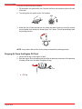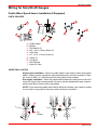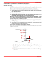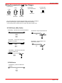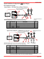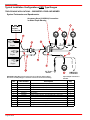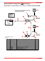
1
INSTALLATION MANUAL 200/225/250 OPTIMAX Important Information . . . . . . . . . . . . . . . . . . . . . . . . . . . . . . . . . . 1 Electric Fuel Pump . . . . . . . . . . . . . . . . . . . . . . . . . . . . . . . . . . . . 2 Boat Horsepower Capacity . . . . . . . . . . . . . . . . . . . . . . . . . . . . . 2 Start in Gear Protection . . . . . . . . . . . . . . . . . . . . . . . . . . . . . . . . 2 Selecting Accessories For The Outboard . . . . . . . . . . . . . . . . . 2 Fuel Tank Installation . . . . . . . . . . . . . . . . . . . . . . . . . . . . . . . . . . 2 Installation Specifications . . . . . . . . . . . . . . . . . . . . . . . . . . . . . . . 3 Lifting Outboard . . . . . . . . . . . . . . . . . . . . . . . . . . . . . . . . . . . . . . . 3 Applying Counter Rotation Decals . . . . . . . . . . . . . . . . . . . . . . . 3 Steering Cable . . . . . . . . . . . . . . . . . . . . . . . . . . . . . . . . . . . . . . . . 4 Steering Link Rod . . . . . . . . . . . . . . . . . . . . . . . . . . . . . . . . . . . . . 5 Determining Recommended Outboard Mounting Height . . . . . 6 Installing Outboard . . . . . . . . . . . . . . . . . . . . . . . . . . . . . . . . . . . . 7 Electrical, Hoses and Control Cables . . . . . . . . . . . . . . . . . . . . . 8 Front Clamp Assembly . . . . . . . . . . . . . . . . . . . . . . . . . . . . . . 8 Remote Wiring Harness . . . . . . . . . . . . . . . . . . . . . . . . . . . . . 9 Battery Cable Size . . . . . . . . . . . . . . . . . . . . . . . . . . . . . . . . . 9 Battery Information . . . . . . . . . . . . . . . . . . . . . . . . . . . . . . . . 10 Battery Cable Connections . . . . . . . . . . . . . . . . . . . . . . . . . 11 Fuel Hose Connection . . . . . . . . . . . . . . . . . . . . . . . . . . . . . 12 Oil Hose Connections . . . . . . . . . . . . . . . . . . . . . . . . . . . . . . 12 Speedometer Tubing Connection . . . . . . . . . . . . . . . . . . . . 12 Water Pressure Tubing Connection . . . . . . . . . . . . . . . . . . Shift Cable Installation . . . . . . . . . . . . . . . . . . . . . . . . . . . . . Throttle Cable Installation . . . . . . . . . . . . . . . . . . . . . . . . . . Filling Fuel System . . . . . . . . . . . . . . . . . . . . . . . . . . . . . . . . . . . Oil Injection Set-Up . . . . . . . . . . . . . . . . . . . . . . . . . . . . . . . . . . . Priming the Oil Injection Pump . . . . . . . . . . . . . . . . . . . . . . . . . Purging Air From the Engine Oil Tank . . . . . . . . . . . . . . . . . . . Propeller Installation . . . . . . . . . . . . . . . . . . . . . . . . . . . . . . . . . . Trim-In Stop Adjustment . . . . . . . . . . . . . . . . . . . . . . . . . . . . . . . Wiring for SmartCraft . . . . . . . . . . . . . . . . . . . . . . . . . . . . . . . . . Paddle Wheel Speed Sensor Installation . . . . . . . . . . . . . Wiring Connections to Paddle Wheel Speed Sensor, Oil Tank and Fuel Tank . . . . . . . . . . . . . . . . . . . . . Typical System Layouts – Single Engine . . . . . . . . . . . . . . Wiring Information for CAN Type Gauges . . . . . . . . . . . . . Wiring Accessories for CAN Type Gauges . . . . . . . . . . . . Typical Installation Configurations CAN Type Gauges . . Wiring Disconnect for Multiple Engines That Share a Common Junction Box . . . . . . . . . . . . . . . . . . . . . . . . . . . . . Configure Engine Location for Multiple Engines That Share a Common Junction Box . . . . . . . . . . . . . . . . . . . . . Typical Installation Configurations Non CAN Type Gauges . . . . . . . . . . . . . . . . . . . . . . . . . . . . . . . . . . . . . 12 13 17 18 19 19 20 21 22 23 23 27 28 30 31 32 36 36 37 NOTICE TO INSTALLER: After completing assembly, these instructions should be placed with the product for the owner’s future use. IMPORTANT: If the boat is to be water tested, the operator should be familiar with the operation procedures in the Operation and Maintenance Manual. Important Information Before Starting Engine Before starting engine for the first time, prime the oil injection pump. Procedure on page 19. CAUTION Prevent possible engine damage, Prime the oil injection pump before starting engine for the first time. Required Fuel Do not use pre-mixed gas and oil in this engine. Use a clean and fresh recommended gasoline during engine break-in and after engine break-in. Recommended Oil Mercury or Quicksilver Optimax/DFI 2-Cycle engine oil is recommended for your engine. If Optimax/DFI 2-Cycle engine oil is not available, we recommend using Mercury or Quicksilver TC-W3 Premium Plus 2-Cycle Oil. Severe engine damage may result from use of an inferior oil Avoiding Fuel Flow Restrictions IMPORTANT: Adding components to the fuel supply system as in filters, valves, fittings, etc. may restrict the fuel flow and could cause engine stalling at low speed, and/ or a lean fuel condition at high RPM, that could cause engine damage. Page 1 of 38 Printed in U.S.A. - 2003, Mercury Marine 90-10202050 MARCH 2004 200/225/250 OPTIMAX Electric Fuel Pump If an electric fuel pump is used, the fuel pressure must not exceed 4 psig at the engine. If necessary, install a pressure regulator to regulate the pressure. Boat Horsepower Capacity U.S. COAST GUARD CAPACITY MAXIMUM HORSEPOWER XXX MAXIMUM PERSON CAPACITY (POUNDS) XXX MAXIMUM WEIGHT CAPACITY XXX Do not overpower or overload the boat. Most boats will carry a required capacity plate indicating the maximum acceptable power and load as determined by the manufacturer following certain federal guidelines. If in doubt, contact your dealer or the boat manufacturer. WARNING Using an outboard that exceeds the maximum horsepower limit of a boat can: 1. cause loss of boat control 2. place too much weight at the transom, altering the designed flotation characteristics of the boat or 3. cause the boat to break apart, particularly around the transom area. Overpowering a boat can result in serious injury, death, or boat damage. Start in Gear Protection The remote control connected to the outboard must be equipped with a start-in-gear protection device. This prevents the engine from starting in gear. WARNING Avoid serious injury or death from a sudden unexpected acceleration when starting your engine. The design of this outboard requires that the remote control used with it must have a built in start-in-gear protection device. Selecting Accessories For The Outboard Genuine Quicksilver Parts and Accessories have been specifically designed and tested for this outboard. Some accessories not manufactured or sold by Quicksilver are not designed to be safely used with this outboard or outboard operating system. Acquire and read the Installation, Operation, and Maintenance manuals for all selected accessories. Fuel Tank Installation PORTABLE FUEL TANK Select a suitable location in boat within engine fuel line length limitations and secure tank in place. PERMANENT FUEL TANK These should be installed in accordance with industry and federal safety standards which include recommendations applicable to grounding, anti-siphon protection, ventilation, etc. Page 2 of 38 200/225/250 OPTIMAX Installation Specifications a a b a – Transom Opening – Minimum Single Engine (Remote) – 33-3/8 in. (848 mm) Dual Engines – 59-3/4 in. (1518 mm) b – Engine Center Line For Dual Engine 26 in. (660mm) Minimum Lifting Outboard Use Flywheel Puller/Lifting Eye (91-83164M). Applying Counter Rotation Decals IMPORTANT: For dual outboard counter rotation installations, the left-hand rotation outboard is generally placed on the port side of boat transom. Apply “COUNTER ROTATION” decal (supplied with left-hand rotation outboard) onto righthand rotation outboard. Match decal placement with left-hand rotation outboard. a b a - Decal (Left-Hand Rotation Outboard) b - Decal (Right-Hand Rotation Outboard) Page 3 of 38 200/225/250 OPTIMAX Steering Cable STARBOARD SIDE ROUTED CABLE 1. Lubricate O-ring seal and entire cable end. 95 95 2-4-C With Teflon (92-825407A12) 2. Insert steering cable into tilt tube. 3. Torque nut to 35 lb. ft. (47.5 N·m). Page 4 of 38 200/225/250 OPTIMAX Steering Link Rod 1. Install steering link rod per illustration. a c d b a b c d - Special Bolt (10-849838) Torque to 20 lb. ft. (27 N·m) - Nylon Insert Locknut (11-34863) Torque to 20 lb. ft. (27 N·m) - Flat Washer (2) - Nylon Insert Locknut (11-34863) Tighten Locknut Until it Seats, Then Back Nut Off 1/4 Turn IMPORTANT: The steering link rod that connects the steering cable to the engine must be fastened using special bolt (“a” - Part Number 10-849838) and self locking nuts (“b” & “c” - Part Number 11-34863). These locknuts must never be replaced with common nuts (non locking) as they will work loose and vibrate off, freeing the link rod to disengage. WARNING Disengagement of a steering link rod can result in the boat taking a full, sudden, sharp turn. This potentially violent action can cause occupants to be thrown overboard exposing them to serious injury or death. Page 5 of 38 200/225/250 OPTIMAX Determining Recommended Outboard Mounting Height 26 in. (660mm) 25 in. (635mm) 24 in. (609mm) b (e) 23 in. Outboard (584mm) Mounting Height (See 22 in. NOTE Below) (560mm) e c 21 in. (533mm) a d 20 in. (508mm) 19 in. (482mm) 10 NOTE: Add 5 in. (127mm) for XL models to the listed outboard mounting height. 20 30 40 50 60 70 80 Maximum Boat Speed Anticipated IMPORTANT NOTICE TO INSTALLER 1. The outboard should be mounted high enough on the transom so that the exhaust relief hole will stay at least 1 in. (25.4 mm) above the water line when the engine is running at idle speed. Having the exhaust relief hole above the water line will prevent exhaust restriction. Exhaust restriction will result in poor performance at idle. 2. However, keep in mind that the mounting height (e) of the outboard must not exceed 25 in. (635 mm) for L models, 30 in. (762 mm) for XL models. Mounting the outboard higher may cause damage to the gear case components. a. This solid line is recommended to determine the outboard mounting height. IMPORTANT: Increasing the height of outboard generally will provide the following: 1) Less steering torque, 2) more top speed, 3) greater boat stability, but, 4) will cause more prop “break loose” which may be particularly noticeable when planing off or with heavy load. c. This line may be preferred to determine outboard mounting height dimension, if maximum speed is the only objective. d. This line may be preferred to determine outboard mounting height dimension for dual outboard installation. e. Outboard mounting height (height of outboard transom b. These broken lines represent the extremes of known brackets from bottom of boat transom). For heights over successful outboard mounting height dimensions. Page 6 of 38 22 in. (560mm), a propeller, that is designed for surfacing operation is usually preferred. 200/225/250 OPTIMAX Installing Outboard 1. Use transom drilling fixture (91-98234A2) or attach (tape) engine mounting template (located in this manual) to boat transom. 2. Mark and drill four 17/32 in. (13.5mm) mounting holes. 3. Refer to “Determining Recommended Outboard Motor Mounting Height,” preceding and install outboard to the nearest recommended mounting height. 4. Fasten outboard with provided mounting hardware shown. d b a c e a - 1/2 in. Diameter Bolts (4) b - Flat Washers(4) c - Locknuts (4) d - Flat Washers (4) e - Marine Sealer - Apply to Shanks of Bolts, Not Threads Page 7 of 38 200/225/250 OPTIMAX Electrical, Hoses, and Control Cables IMPORTANT: Warning Horn Requirement – The remote control or key switch assembly must be wired with a warning horn. This warning horn is used with the engine warning system. Front Clamp Assembly REMOVAL Remove two screws with retainer and open the front clamp. a a b c 57803 a - Screws (2) b - Retainer c - Clamp INSTALLATION IMPORTANT: Sufficient slack must exist in engine wiring harness, battery cables, fuel hose, and oil hoses routed between clamp and engine attachment point, to relieve stress and prevent hoses from being kinked or pinched. 1. Place the neoprene wrap around the wiring, hoses, and control cables as shown. 57840 2. Secure both halves of clamp with sta-strap. 57802 Page 8 of 38 200/225/250 OPTIMAX 3. Secure clamp assembly into bottom cowl with retainer and 2 screws. b b a 57803 a - Retainer b - Screws Remote Wiring Harness 1. Connect wiring. Place harness into the holder. BLU/WHT GRN/WHT BLU/WHT GRN/WHT TAN TAN BRN/WHT BRN/WHT a b c 57789 a - Power Trim Connections b - Wire Connection For Non SmartCraft Water Temp Gauge c - Connection For Non SmartCraft Analog Trim Gauge Battery Cable Size If standard (original) battery cables are replaced with longer cables, the wire gauge size must increase. See chart following for correct wire gauge size. ÎÎ ÎÎ Wire Gauge Size Battery Cable Length Page 9 of 38 200/225/250 OPTIMAX Battery Cable Wire Gauge Size Mercury/Mariner Outboards Battery Cable Length 8 ft. 9 ft. 10ft. 11ft. 12ft. 13ft. 14ft. 15ft. 16ft. 17ft. 18ft. 19ft. 20ft. 21ft. 22ft. 23ft. 24ft. 2.4m 2.7m 3.0m 3.4m 3.7m 4.0m 4.3m 4.6m 4.9m 5.2m 5.5m 5.8m 6.1m 6.4m 6.7m 7.0m 7.3m Models Wire Gauge Size No. SAE 6-25 Hp #8* #8 #6 #6 #6 #6 #4 #4 #4 #4 #4 #4 #4 #4 #2 #2 #2 30-115 Hp #6* #4 #4 #4 #4 #4 #2 #2 #2 #2 #2 #2 #2 #2 #0 #0 #0 #6* #6 #4 #4 #4 #4 #4 #4 #2 #2 #2 #2 #2 #2 #2 #4* #2 #2 #2 #2 #2 #2 #2 #2 #2 #0 #0 #0 125-250 Hp (except DFI) DFI Models * = Standard (original) Cable Length and wire gage size. Battery Information CAUTION Hex huts must be used to secure battery to battery posts to avoid loss of electrical power. Do not use deep cycle batteries. Engines must use a marine starting battery with 1000 MCA or 800 CCA. When connecting engine battery, hex nuts must be used it secure battery leads to battery posts. Torque nuts to 13.5 Nm (120 lb. in.). IMPORTANT: Battery cable size and length is critical. Refer to battery cable wire gauge chart for size requirements. Decal needs to be placed in or near battery box for future service reference. One 5/16/in/ and one 3/8 in. hex nut are supplied per battery for wiring nut replacement. Metric hex nuts are not supplied. Page 10 of 38 200/225/250 OPTIMAX Battery Cable Connections SINGLE OUTBOARD b c (+) a (–) a b c d d - Black Sleeve (Negative) - Red Sleeve (Positive) - Hex nuts – Torque to 13.5 Nm (120 lb. in.) - Starting Battery DUAL OUTBOARDS Connect a common ground cable (wire size same as engine battery cables) between negative (–) terminals on starting batteries. (–) e (–) e - Ground Cable (Same Wire Size As Engine Battery Cable) – Connect Between Negative (–) Terminals Page 11 of 38 200/225/250 OPTIMAX Fuel Hose Connection Fuel Hose Size – Minimum fuel line inside diameter (I.D.) is 5/16 in. (8mm), with separate fuel line/fuel tank pickup for each engine. Fasten remote fuel hose to fitting with hose clamp. Oil Hose Connections Connect the remote oil hoses to the engine hose connections as shown. Fasten hose connections with sta-straps. Speedometer Tubing Connection (Models without SmartCraft Speedometer) This outboard has a speedometer water pick-up located in the leading edge of the gear case. If you want to use this water pickup for the speedometer, disconnect the water pickup tubing from the speedometer sensor and route tubing out of the cowl. Install coupler (provided with outboard) on end of tubing. Water Pressure Tubing Connection (Models without SmartCraft Water PSI Gauge) Make the water pressure gauge hose connection to this tubing as shown. h d c e f g j i l a b c d e f g h i j k b a - Remote Fuel Hose - Hose Clamp – Secure Remote Fuel Hose - Oil Hoses with Blue Stripe - Secure With Sta-Strap - Oil Hoses without Blue Stripe - Secure With Sta-Strap - Sta-Strap (2) - Secure Oil Hoses - Speedometer Water Pickup Tubing (Black Color) - Water Pressure Tubing (Gray Color) - Coupler (859747) – Push In on End of Coupler to Disconnect Plug or Tubing - Plug (if equipped) – Remove when Making Coupler Connection - Barb Hose Fitting (2) (859731) Provided with Outboard – Install this fitting into Coupler, if a Rubber Hose Connection is Required k - Speedometer Hose – Insert the barb hose fitting (j) into Coupler and Connect Hose l - Water Pressure Tube – Insert into Coupler, Pull on Tube to Verify That it is Locked Page 12 of 38 200/225/250 OPTIMAX Shift Cable Installation Install cables into the remote control following the instructions provided with the remote control. NOTE: Prior to installing shift and throttle cables on engine, for ease of installation, it is recommended that the bottom cowl be loosened and spread apart to avoid possibly kinking control cables during installation. 1. Remove the front clamp. a a - Clamp 2. Separate the front end of the bottom cowl as follows: a. Remove the 2 front screws (a) and loosen the rear 2 screws (b). b. Separate the bottom cowl. b a b a - Remove Front Screws b - Loosen Rear Screws - Remove Rubber Plug for Access to Lower Screw NOTE: Install the shift cable to the engine first. The shift cable is the first cable to move when the remote control handle is moved out of neutral. Page 13 of 38 200/225/250 OPTIMAX Counter Rotation Outboards Counter rotating (left hand) gear cases can be identified by a “L” stamped into the end of the propeller shaft. The Quicksilver Dual Engine Console Mount Control, P/N 88688A22 or 88688A52, is required to shift the counter rotation outboard. The installation instructions shipped with the control explain the procedure required to connect this control to a counter rotation outboard. IMPORTANT: If the counter rotation outboard is rigged similar to a standard rotation outboard OR if a standard rotation outboard is rigged similar to a counter rotation outboard, the reverse gear and bearing in the gear case must function as forward gear. THE REVERSE GEAR/BEARING ARE NOT DESIGNED TO CARRY THE SUSTAINED LOADS THAT ARE GENERATED WHEN RUNNING UNDER CONSTANT HIGH RPM AND THRUST CONDITIONS. OUTBOARD SHIFTING DIRECTION On counter rotation outboards, the shift linkage moves in the opposite direction compared to a standard rotation outboard. STANDARD ROTATION GEAR OUTBOARDS Forward Gear Reverse Gear COUNTER ROTATION OUTBOARDS Reverse Gear Page 14 of 38 Forward Gear 200/225/250 OPTIMAX Installation IMPORTANT: Step 1 must be followed for proper adjustment of the shift cable. 1. Locate the center point of the slack or lost motion that exists in the shift cable as follows: a. Move the remote control handle from neutral into forward and advance the handle to full speed position. Slowly return the handle back to the neutral. Place a mark (a) on the cable against the cable end guide. b. Move the remote control handle from neutral into reverse and advance the handle to full speed position. Slowly return the handle back to the neutral. Place a mark (b) on the cable against the cable end guide. c. Make a center mark (c), midway between marks (“a” and “b”). Align the cable end guide against this center mark when installing cable to the engine. STANDARD ROTATION OUTBOARDS a b c COUNTER ROTATION OUTBOARDS a b c Page 15 of 38 200/225/250 OPTIMAX 2. Position remote control and outboard into neutral. N 3. Slide the shift cable retainer forward until resistance is felt, then slide cable anchor toward rear until resistance is felt. Center the anchor pin between resistance points. a a - Anchor Pin 4. Align the shift cable end guide with the center mark as instructed in Step 1. 5. Place shift cable on anchor pin. Adjust cable barrel so it slips freely into the barrel holder. 6. Secure shift cable with shift cable retainer. a c d b a - Cable Barrel b - Shift Cable Retainer c - Locknut – Tighten locknut then back off locknut 1/4 turn d - Nylon Washer 7. Check shift cable adjustments as follows: a. With remote control in forward, the propshaft should lock solidly in gear. If it does not, adjust cable barrel closer to cable end guide. b. Shift remote control into neutral. The propshaft should turn freely without drag. If not, adjust barrel away from cable end guide. Repeat steps a and b. Page 16 of 38 200/225/250 OPTIMAX c. Shift remote control into reverse while turning propeller. The propshaft should lock solidly in gear. If not, adjust barrel away from cable end guide. Repeat steps a thru c. d. Return remote control handle to neutral. The propeller should turn freely without drag. If not, adjust barrel closer to cable end guide. Repeat steps a thru d. Throttle Cable Installation 1. Position remote control into neutral. N 2. Attach throttle cable to the throttle lever. Secure with washer and locknut. a b a - Nylon Washer b - Locknut – Tighten locknut then back off locknut 1/4 turn 3. Adjust the cable barrel so that the installed throttle cable will hold the idle stop screw against the stop. b a a - Cable Barrel – Adjust To Hold Idle Stop Screw Against Stop b - Idle Stop Screw Page 17 of 38 200/225/250 OPTIMAX 4. Check throttle cable adjustment as follows: a. Shift outboard into gear a few times to activate the throttle linkage. Make sure to rotate the propeller shaft while shifting into reverse. F N R b. Return remote control to neutral. Place a thin piece of paper between idle adjustment screw and idle stop. Adjustment is correct when the paper can be removed without tearing, but has some drag on it. Readjust cable barrel if necessary. IMPORTANT: The idle stop screw must be touching the stop. a b a - Idle Stop Screw b - Idle Stop 5. Lock the barrel holder in place with the cable latch. Filling Fuel System NOTE: For initial start of a new engine or for an engine that ran out of fuel, or was drained of fuel, the fuel system should to be filled as follows: Page 18 of 38 • Squeeze the fuel line primer bulb until it feels firm. • Turn the ignition key switch to the ON position for three seconds. This operates the electric fuel pump. 200/225/250 OPTIMAX • Turn the ignition key switch back to the OFF position, and squeeze the primer bulb again until it feels firm. Turn the ignition key switch to the “ON” position again for three seconds. Continue this procedure until the fuel line primer bulb stays firm. Oil Injection Set-Up 1. Fill remote oil tank with the recommended oil listed in the Operation and Maintenance Manual. Tighten fill cap. a a - Fill Cap 2. Remove cap and fill engine oil tank with oil. Reinstall the fill cap. b a a - Engine Oil Tank b - Fill Cap Priming the Oil Injection Pump Before starting engine for the first time, prime the oil injection pump. Priming will remove any air that may be in the pump, oil supply hose, or internal passages. a b 57916 a - Oil Injection Pump b - Oil Supply Hose CAUTION To prevent damage to the fuel pumps, fill the engine fuel system with fuel. Otherwise the fuel pumps will run without fuel during the priming process. Page 19 of 38 200/225/250 OPTIMAX Prime the oil injection pump as follows: 1. Fill the engine fuel system with fuel. Connect fuel hose and squeeze primer bulb until it fells firm. 2. Turn the ignition key switch to the “ON” position. 3. Within the first 10 seconds after the key switch has been turned on, move the remote control handle from neutral into forward gear 3 to 5 times. This will automatically start the priming process. N F NOTE: It may take a few minutes for the pump to complete the priming process. Purging Air From the Engine Oil Tank 1. Loosen the fill cap on the engine oil tank. 2. Start the engine. Run the engine until the all the air has been vented out of the tank and oil starts to flow out of the tank. Re-tighten fill cap. a a - Fill Cap Page 20 of 38 200/225/250 OPTIMAX Propeller Installation WARNING If the propeller shaft is rotated while the engine is in gear, there is the possibility that the engine will crank over and start. To prevent this type of accidental engine starting and possible serious injury caused from being struck by a rotating propeller, always shift outboard to neutral position and remove spark plug leads when you are servicing the propeller. Flo-Torq I Drive Hub Propellers bb ee a b c d e c dd aa - Forward Thrust Hub - Continuity Washer - Thrust Hub - Propeller Nut Retainer - Propeller Nut Flo-Torq II Drive Hub Propellers ee dd a b c d e cc b aa - Forward Thrust Hub - Replaceable Drive Sleeve - Rear Thrust Hub - Propeller Nut Retainer - Propeller Nut 1. Tighten propeller nut to 55 lb-ft (75 Nm). Bend tabs against nut. a bb a - Propeller Nut - Torque To 55 lb-ft (75 Nm) b - Bend Tabs Into Grooves Page 21 of 38 200/225/250 OPTIMAX Trim-In Stop Adjustment Some outboard boats, particularly some bass boats, are built with a greater than normal transom angle which will allow the outboard to be trimmed further “in” or “under”. This greater trim “under” capability is desirable to improve acceleration, reduce the angle and time spend in a bow high boat attitude during planing off, and in some cases, may be necessary to plane off a boat with aft live wells, given the variety of available propellers and height range of engine installations. However, once on plane, the engine should be trimmed to a more intermediate position to avoid a bow-down planing condition called “plowing”. Plowing can cause “bow steering” or “over steering” and inefficiently consumes horsepower. In this condition, if attempting a turn or encountering a diagonal, moderate wake, a more abrupt turn than intended may result. In rare circumstances, the owner may decide to limit the trim under. This can be accomplished by purchasing a stainless steel tilt pin (P/N 17-49930A1) and inserting it through whatever pin hole is desired. The non-stainless steel shipping bolt should not be used in this application other than on a temporary basis. WARNING Avoid possible serious injury or death. Adjust outboard to an intermediate trim position as soon as boat is on plane to avoid possible ejection due to boat spin-out. Do not attempt to turn boat when engine is trimmed extremely under or in. a a - Tilt Pin Page 22 of 38 200/225/250 OPTIMAX Wiring for SmartCraft Gauges Paddle Wheel Speed Sensor Installation (If Equipped) PARTS PROVIDED b j f a f h e i c a b c d e f g h i j d g - Paddle Wheel - Bracket - Flat Washer (2) - #10 - 3/4 in. (19 mm) Screw (2) - Cable Cap - # 6 - 1/2 in. (12 mm) Screw (4) - Clamp (2) - Connector - Wire Retainer - Spare Pin Yoke SELECTING LOCATION Single engine installation – Mount on paddle wheel on the transom where the propeller blade is rotating upward. [usually the right (starboard) side] to minimize cavitation. If feasible, mount at least 2 in. (50mm) beyond the swing radius of the propeller. Dual engine installation – Mount the paddle wheel between the engines as close to the center line (keel) of the boat as possible. On slower, heavier displacement boats, however, positioning it farther from the keel is acceptable. NOTE: Do not mount the paddle wheel directly behind any strakes, ribs, intakes or outlets for live wells or any protrusion that may cause turbulence or cavitation. 2 in. (50mm) Page 23 of 38 200/225/250 OPTIMAX Paddle Wheel Speed Sensor Installation (If Equipped) TRANSOM ANGLE REQUIREMENTS Standard 13° to 20° transoms – No special adjustments required. Stepped or undercut transom with 3° angles – A small shim of tapered plastic, metal or wood must be fabricated and installed as shown. Mount the paddle wheel on the step for best performance. 13° Transom Angle OK 20° Transom Angle OK Shim NO Stepped Transom OK Stepped Transom Stepped Transom INSTALLING BRACKET 1. Cut out the template an the end of this installation manual.. At the location you’ve selected, tape the template to the transom. Make sure the black dotted line on the template is aligned with the transom’s bottom edge, as shown. 2. Using a #28 or 9/64 in. bit, drill two 7/8 in. (22 mm) deep where indicated on the template. To prevent drilling too deeply, wrap masking tape around the drill 7/81 (22 mm) from the point. NOTE: In fiberglass hulls, first chamfer the gelcoat using a 1/4 in. (6mm) drill and drilling about 1/16 in. (15 mm) deep to prevent surface cracks. 3. To prevent water seepage into the transom, apply a marine sealant (such as RTV) to the two #10 screws provided. Using the washers provided, attach and tighten the bracket to the hull making sure the bracket is flush with the underside of the hull. 4. Fill any gap between the housing and the transom with a caulking material, as shown. Using a putty knife, smooth the surface to ensure proper water flow. a Caulking 2 in. (50mm) b a - Template b - #10 Screw (2) c - Flat Washer (2) Page 24 of 38 c 200/225/250 OPTIMAX Paddle Wheel Speed Sensor Installation (If Equipped) ROUTING THE CABLE NOTE: You can choose to drill a hole through the transom for routing the cable, or you can route the cable over the transom or through a drain hole above the water line. If you choose to drill a hole through the transom, follow these instructions: 1. Select a transom location for the hole above the water line that does not interfere with other cables and controls. 2. Drill a 5/8 in. (15 mm) diameter Hole. 3. Route the cable through the drilled hole. Seal the transom hole with silicone (RTV) or a comparable marine sealant after you routed the cable through. NOTE: The hole for the first clamp should be l in. (25 mm) above the paddle wheel. The hole for the second clamp should be positioned halfway between the first clamp and the cap covering the transom hole you drilled for the cable. 4. Using a 7/64 in. (2.8 mm) bit, drill holes for the clamps and cap approximately 1/2 in. (13 mm) deep. 5. Apply silicone (RTV) or a comparable marine sealant to the screw threads and Install the cable clamps and the cable feed-thru cap. If you choose not to drill a hole through the transom: If you prefer not to drill a hole, route the cable over the transom or through a drain hole that is above the water line. d c b a 1 in. (25.4 mm) a - The First Clamp Should be Placed 1 in. (25 mm) Above the Paddle Wheel b - The Second Clamp Should be Positioned Halfway Between the First Clamp and the Cable Cap c - Cable Cap d - If You Prefer Not to Drill A Hole, Route the Cable Over the Transom or Through a Drain Hole Page 25 of 38 200/225/250 OPTIMAX Paddle Wheel Speed Sensor Installation (If Equipped) INSTALLING AND REMOVING THE PADDLE WHEEL Installation – slide the pins into the slots in the bracket and snap the tabs into place. Removal – squeeze open (unlock) the tabs and pull up on the paddle wheel. b a a - Pins b - Tabs WIRE CONNECTIONS IMPORTANT: Before making wire connections, make sure wires are routed through the transom. NOTE: Wires can only be pushed into the connector one way. Align the wire terminal with the tabs inside the connector. 1. Have the wiring routed through the transom. 2. Push each wire terminal into its respective location in the connector. Push wires in until they snap into place. 3. Secure wires into connector with the wire retainer. WHITE YELLOW BLUE BLACK a b a - Connector b - Wire Retainer Page 26 of 38 b 200/225/250 OPTIMAX Wiring Connections to Paddle Wheel Speed Sensor, Oil Tank and Fuel Tank a IMPORTANT: DO NOT connect the Black/Orange wire to the fuel tank sensor when there is a engine battery ground strap connected to the fuel tank or sender assembly. If not used, plug the unused open bullet connector with rubber plug P/N 13541. 84-859743T2 859223 b a b c d Oil Tank Sender 816190A1 c d 57738 - Electronic Control Module (ECM) - Paddle Wheel Speed/Outside Water Temp Sensor (If Equipped) - Oil Tank - Fuel Tank Page 27 of 38 200/225/250 OPTIMAX Typical System Layouts – Single Engine Product Configurations Speedometer and Tachometer Non CAN Type Gauges NOTE: Non CAN type gauges can be used on all V-6 Model outboards that are equipped for SmartCraft Tachometer Speedometer Key Switch Standard Key Switch Harness 5 Pin Tachometer Plug CAN Type Gauges NOTE: CAN Type Gauges Can only be used on 2002 Model Year and newer V-6 model outboards that are equipped for SmartCraft Speedometer Tachometer GPS Connection System Link Gauges SC Data Cable Terminator Junction Box Page 28 of 38 + – System Link Connector 200/225/250 OPTIMAX Typical System Layouts – Single Engine Product Configurations System Monitor (CAN) NOTE: System Monitor can be used on 2001 model year and newer outboards that are equipped for SmartCraft System Monitor System Link Gauges System Link Connector SC1000-2RSL System Monitor Harness Tachometer Only CAN Type Gauge NOTE: CAN Type Gauges Can only be used on 2002 Model Year and newer outboards that are equipped for SmartCraft System Tachometer System Link Gauges System Link Connector SC1000-2RSL System Monitor Harness Page 29 of 38 200/225/250 OPTIMAX Wiring Information for CAN Type Gauges REQUIREMENTS SmartCraft communications are via the Controller Area Network (CAN), electrically implemented on a twisted pair of wires. signals. Note: SmartCraft harnesses include other signals besides CAN. The maximum distance between any two modules on the SmartCraft bus is 40 meters (130 feet). This distance is calculated as the total harness length between the modules (trunk length plus drop lengths). There must be exactly two termination resistors on the CAN bus. No more than 20 modules may be connected to the bus. This is the maximum number of connections supported by the engine control module software. INSTALLATION GUIDELINES SmartCraft installations should use Mercury Marine harnesses and junction boxes. This assures a robust mechanical implementation as well as proper connection of all signals. The ideal installation uses a single trunk line with short drops to individual modules. Two termination resistors, one at each end of the trunk line, minimize signal reflections. Signal reflections can increase radio frequency interference and the potential for bit errors on the bus. The trunk line is not defined by junction boxes. The trunk should be considered to be the distance between the termination resistors. Drops may be at the ends of the trunk line or anywhere else that is convenient for the installation. Note that the trunk line can “loop-back” in some installations. • • • • • Page 30 of 38 The single engine System Monitor example on page 32 illustrates a trunk line with two drops of essentially zero length, one at the engine and the other at the gauge. The single engine System Tach and Speedo example on page 32 illustrates a trunk line with one zero length drop at the engine and two three foot drops at the gauges. The dual engine examples on page 33 illustrates a 60 foot trunk line with two zero length drops at the engines and two (or three) three foot drops at the gauges. The triple engine example on page 34 illustrates a 45 foot trunk line with a zero length drop at one engine, two 10 foot drops (at the other engines), and four three foot drops at the gauges. The trunk line in the single engine dual station example on page 35 is the length of “a” plus the length of “f” There is a zero length drop at the engine and two three foot drops to the monitors. 200/225/250 OPTIMAX Wiring Accessories for CAN Type Gauges Junction Boxes 6 Way 8 Way ** Junction Box Weather Cap * Junction Box Terminator/Resistor 4 Way 859318T-2 859318T-1 878492A4 878492A6 878492A8 * For correct placement on these terminator/resistors, refer to Wiring Installation Guidelines preceding and Typical Installation configurations following. * * All unused junction box ports must be covered using these weather caps. SC1000 Series (Blue Cable) 84-879968T_ Harness without Terminator/Resistor 6 Ft 10 Ft 15 Ft 20 Ft 30 Ft 84-879981T_ Harness with Terminator/ Resistor on One End 10 Ft 15 Ft 20 Ft 30 Ft 84-879978T-1 System Speed Harness 3 Ft 84-879979T-1 System Monitor and Tachometer Harness 3 Ft 84-879982T_ Harness with Terminator/ Resistor on Both Ends 20 Ft 30 Ft SC100 Series 84-880756b_ System Link Extension Harness 3 Ft 10 Ft 30 Ft Page 31 of 38 200/225/250 OPTIMAX Typical Installation Configurations CAN Type Gauges NOTE: The typical installation configurations shown on this page and the next few pages are the lowest cost solutions. Other solutions are also possible. See Page 15 for general guidelines. SINGLE ENGINE APPLICATIONS System Monitor– 2001 Model Year and Newer Monitor b Accessory Horn (816492A9) Connection for Water Depth Warning a System Link Connection Engine Optional Depth Transducer c Ref. Part Number Description Qty. a 879982T_ Wiring Harness SC1000-2RSL (20,30 ft) 1 b 879896K2 System Monitor – Front Mount (Outboard Only) 1 b 879896K1 System Monitor – Rear Mount (Outboard Only) 1 b 879896K4 System Monitor 2 – Front Mount (All Models) 1 b 879896K3 System Monitor 2 – Rear Mount (All Models) 1 c 881931A1 Depth Transducer – Transom Mount 1 c 881932A1 Depth Transducer – In Hull 1 c 881933A1 Depth Transducer – Through Hull 1 d System Tach and Speedo – 2002 Model Year and Newer Accessory Horn (816492A9) Connection for Water Depth Warning e f Optional Depth Transducer is Available a Termination Resistor On This End BLUE Engine WHITE b c + – Air Temp Sensor NMEA GPS Connection Ref. Part Number a 879981T_ Wiring Harness SC1000R (10,15,20,30ft) 1 b 859318T1 Terminator/Resistor 1 c 878492T_ Junction Box (4,6,8) 1 d 879899K1 System Speedo and Tach – Single Application Kit – Gray Color 1 d 879899K11 System Speedo and Tach – Single Application Kit – White Color 1 e 879978T1 Wiring Harness SC1000-(3ft) Speed Harness 1 f 879979T1 Wiring Harness SC1000-SL-(3ft) Tach Harness 1 Page 32 of 38 Description Qty. 200/225/250 OPTIMAX Typical Installation Configurations CAN Type Gauges DUAL ENGINE APPLICATIONS System Monitor – 2001 Model Year and Newer Outboards c c Accessory Horn (816492A9) Connection for Water Depth Warning a Engine Termination Resistor On This End Engine d e d b Optional Depth Transducer is Available IMPORTANT: Make Wiring Disconnect On One Of The Engines. Refer to Wiring Disconnect for Multiple Engine s That Share A Common Junction Box following. Ref. Part Number Description Qty. a 879981T30 Wiring Harness SC1000R (30 ft) 2 b 879979T1 Wiring Harness SC1000-SL-(3ft) Tach Harness 2 c 879896K2 System Monitor – Front Mount (Outboard Only) 2 c 879896K4 System Monitor 2 – Front Mount (All Models) 2 d 859318T2 Weather Cap 2 e 878492T6 Junction Box 1 System Tach and Speedo – 2002 Model Year and newer Accessory Horn (816492A9) Connection d Optional Depth Transducer is Available for Water Depth Warning Sp ee d a Engine b f c IMPORTANT: Make Wiring Disconnect On One Of The Engines. Refer to Wiring Disconnect for Multiple Engine s That Share A Common Junction Box following. Air Temp Sensor Description BLUE WHITE Engine Termination Resistor On This End e + – NMEA GPS Connection Ref. Part Number Qty. a 879981T30 Wiring Harness SC1000R (30 ft) 2 b 859318T2 Weather Cap 1 c 878492T6 Junction Box 1 d 879899K2 System Speedo and Tach – Dual Application Kit – Gray Color 1 d 879899K12 System Speedo and Tach – Dual Application Kit – White Color 1 e 879978T1 Wiring Harness SC1000-(3ft) Speed Harness 1 f 879979T1 Wiring Harness SC1000-SL-(3ft) Tach Harness 2 NOTE: A junction box may be added to connect dual engine installation to single wiring harness running forward to dash. See wiring installation guidelines. Page 33 of 38 200/225/250 OPTIMAX Typical Installation Configurations CAN Type Gauges TRIPLE ENGINE APPLICATIONS – 2002 MODEL YEAR AND NEWER System Tachometer and Speedometer Accessory Horn (816492A9) Connection for Water Depth Warning j Termination Resistor On This End g h a d f Engine i Engine Air Temp Sensor IMPORTANT: Make Wiring Disconnect On One Of The Engines. Refer to Wiring Disconnect for Multiple Engine s That Share A Common Junction Box following. Part Number Description g – NMEA GPS Connection Optional Depth Transducer is Available Qty. a 84-879982T15 Wiring Harness SC1000R-15 (15 ft) 1 b 84-879968B10 Wiring Harness SC1000 (10 ft) 2 c 84-879968B30 Wiring Harness SC1000 (30 ft) 1 d 859318T1 Terminator/Resistor 1 e 878492T6 Junction Box 1 f 878492T4 Junction Box 1 g 879899K2 System Speedo and Tach – Dual Application Kit – Gray Color 1 g 879899K12 System Speedo and Tach – Dual Application Kit – White Color 1 h 879897K1 Extra System Tachometer – Gray Color 1 h 879897K11 Extra System Tachometer – White Color 1 i 879978T1 Wiring Harness SC1000-(3ft) Speed Harness 1 j 879979T1 Wiring Harness SC1000-SL-(3ft) Tach Harness 3 Page 34 of 38 + e b Ref. BLUE Engine WHITE c 200/225/250 OPTIMAX Typical Installation Configurations CAN Type Gauges SYSTEM MONITOR – SINGLE ENGINE – DUAL STATION – 2001 MODEL YEAR AND NEWER e Accessory Horn (816492A9) Connection for Water Depth Warning Terminator /Resistor On This End TAN/BLUE PURPLE d System Link Connection a g c Engine e f b c System Link Connection d Optional Depth Transducer is Available Ref. Part Number g Description Qty. a 879982T_ Wiring Harness SC1000R (10,30ft) 1 b 859318T1 Terminator/Resistor 1 c 878492T_ Junction Box (4,6,8) 2 d 859318T2 Weather Cap 2 e 879896K2 System Monitor – Front Mount (Outboard Only) 2 e 879896K1 System Monitor – Rear Mount (Outboard Only) 2 e 879896K4 System Monitor 2 – Front Mount (All Models)) 2 e 879896K3 System Monitor 2 – Rear Mount (All Models) 2 f 878968T_ Wiring Harness SC1000 1 g 879979T1 Harness SC1000-SL (3ft) Tach Harness 2 Page 35 of 38 200/225/250 OPTIMAX Wiring Disconnect for Multiple Engines That Share a Common Junction Box CAUTION Prevent possible engine electrical component damage, Make this wiring disconnect before powering up the engines. Each CAN Bus must only be powered from one engine. On dual engine installations that share a common junction box (as shown), the CAN Bus power (3 wire) connector on one of the engines must be disconnected. The CAN Bus power connector is located in the engine wiring approximately 3 in. from the SmartCraft Harness connector. Seal both ends of the power connector with caps. On triple engine installations, the CAN Bus power connector must be disconnected on 2 engines. Common Junction Box Engine Engine Cap 881176A1 Cap 881175A1 SmartCraft Harness Connector on Engine RED/BLK BLK PPL RED BLK PPL BLUE WHITE Configure Engine Location for Multiple Engines That Share a Common Junction Box NOTE: Engine location will allow user to configure multi engine installations with-in the SmartCraft network. All engines shipped from the factory are ECM configured as a starboard outside engine. For example, if a dual engine installation is desired, then the appropriate engine ECM needs to be reprogrammed to an outside port engine. Doing this will make sure the correct ECM data is transmitted to the correct set of SmartCraft gauges. Configure the engine ECM’s Using the Digital Diagnostic Terminal (DDT) along with SmartCraft Engine Diagnostic Cartridge Version 1.0 or newer. Follow instructions in the reference manual provided with the Diagnostic Cartridge for setting the engine locations. After the engines have been configured using the DDT, calibrate the SmartCraft gauges to read the correct engine. Page 36 of 38 200/225/250 OPTIMAX Typical Installation Configurations Non CAN Type Gauges + 12 Volt (Connect to Same Circuit as Engine Starting Battery) + 12 Volt (Connect to RED Same Circuit as Engine Starting Battery) RED Tachometer Single Engine BRNWHT GRY Speedometer Tachometer Dual Engine BRNWHT GRY ECM 84-859314A1 84-859315A1 Connection For Optional Visual Warning Light Key Switch Harness Tachometer/Accessory Plug Air Temp Sensor BLUE Diagnostic Port Plug WHITE TAN/BLUE + – NMEA GPS Connection Drilling Template – Paddle Wheel Speed Sensor Drill here Align dotted line with transom bottom edge and fold under fold line fold line Page 37 of 38 200/225/250 OPTIMAX Products of Mercury Marine W6250 Pioneer Road Fond du Lac, WI 54936-1939 Page 38 of 38 The following are registered trademarks of Brunswick Corporation: Autoblend, Force, Jet-Prop, Mariner, Merc, MerCathode, MerCruiser, Mercury, Mercury Marine, Quicksilver, Ride-Guide, and Thruster.