1
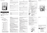
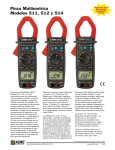
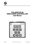
AC/DC True RMS Power Clamp Meter
ELECTRONIC TEST INSTRUMENTS
MODEL 325
CONTENTS
1. FEATURES ................................................ 2
2. Safety precaution ........................................ 2
Symbols Description .................................... 3
3. Specifications.............................................. 4
4. Electrical Specifications ................................ 4
800A rms ........................................... 4
800Arms (60 second).............................. 4
DC 500V AC500V rms ............................ 5
600V rms ........................................... 6
DC600V
........................................... 6
AC600V rms.......................................... 6
5. Instrument Description (fig.1)......................... 6
6. Alignment marks ......................................... 8
7. Measurement .............................................. 8
7-1. DC Current (DCA) measurement ............. 8
7-2. AC Current (ACA) measurement .............. 9
7-3. DC Voltage (DCV) measurement ............. 10
7-4. AC Voltage (ACV) measurement .............. 10
7-5.AC+DC Watt Measurement ...................... 11
7-6.Resistance measurements....................... 11
7-7.Continuity Tests ..................................... 12
7-8.Frequency measurements ....................... 13
7-9.Function key descriptions ........................ 13
? HOLD function.................................... 13
? ZERO relative function......................... 14
? MAX MIN function ............................... 14
? PEAK –H (PEAK HOLD) function........... 15
? AUTO POWER OFF function ................ 16
7-10. Measuring non-sinusoidal quantity ......... 16
? TRUE RMS MEASUREMENT ............... 16
? WAVEFORM COMPARISON ................ 17
? Battery Replacement ........................... 18
? Maintenance and Cautions ................... 19
325
1.
FEATURES
Thank you for purchasing this instrument. Please read
this instruction manual carefully and completely before
using the digital clamp meter. Correct operation will
insure the best performance and decrease the
possibility of damages.
2.
SAFETY PRECAUTION
CAUTION
Take extreme care for the
conditions while measuring
following
1. Measuring voltage over 20V as it may cause human
body electricity conduction.
2. Measure AC power.
3. Do not measure voltage, current under humid or wet
environment.
4. If any unusual condition (such as: breakage,
deformation, fracture, foreign substance, no display,
etc.) of the test leads end (metal part) and
attachment of the meter, please do not conduct any
measurement.
5. Do not contact any exposed metal (conductive)
parts, such as : end of test lead, jack, fixing object,
circuit, etc .
6. Keep you insulated from the object waiting for being
measured.
7. Do not operate the meter under the environment
with explosive gas (material), combustible gas
(material) steam or filled with dust.
EN-2
325
8. In order to avoid reading incorrect data, replace the
battery immediately when the symbol “ ” appears
on the LCD.
9. In order to avoid the damage caused by
contamination or static electricity, do not touch the
circuit board before you take any adequate action.
10. Operating Environment: Indoors use. This
instrument has been designed for being used in an
environment of pollution degree 2.
11. Operation Altitude: Up to 2000M.
12. Operating Temperature & Humidity: 5 ? ~ 40 ?
,below 80%RH.
13. Storage Temperature & Humidity: -10? ~ 60? ,
below 70%RH.
14. Fingers should hold under the protection guard of
test probe.
15. Category: EN 61010-1(2001) and EN 61010-2032(2002) CAT ? 600V & CAT ? 1000V
16.SYMBOLS DESCRIPTION
DC Voltag e or Current
AC Voltage or Current
DC/AC Voltage or Current
Ground
Meter Double insulated
Caution
Danger high voltage: risk of electric shock
Application around and removal from
hazardous live conductors is permitted
EN-3
325
3.
SPECIFICATIONS
1. Display: 3 3/4 digits LCD with max. reading 3999,
plus decimal point, unit symbol indication.
2. Overload Indication: LCD will show “OL” in the left
highest position.
3. Low Battery Indication: Replace battery immediately
when LCD displays “ ”.
4. Sampling Rate: 2 times per second for digital display.
5. Power Supply: 9V NEDA 1604 IEC 6F22 JIS 006P
battery x 1pc.
6. Battery Life: About 200 hours.
7. Jaws opening: Max. 36 mm.
8. Conductor size: Max. 35mm.
9. Dimension: 218mm(L)x75mm(W)x43mm(H).
10.Weight: About 375g. (Including battery)
11.Accessories : Test Leads ? manual? carrying case ?
battery.
4.
ELECTRICAL SPECIFICATIONS
Accuracy: ±(..%rdg…dgt)at 23? ±5? , below 80? RH
DCA
Range
Resolution
Accuracy
400A
0.1A
± (1.5%+5)
Overload Protection
800A rms
(60 second)
600A
1A
± (2.0%+5)
Range
Resolution
Accuracy
50Hz~60 Hz
Overload Protection
400A
0.1A
± (2.0%+5)
600A
1A
± (2.5%+5)
800Arms
(60 second)
ACA
EN-4
325
AC CURRENT (TRUE RMS:From 10% to 100% of
range)
Range
400A
600A
Resolution
0.1A
1A
Accuracy
40Hz~65Hz 65Hz~1kHz
± (2.0%+5) ± (3.0%+8)
± (2.0%+5)
± (3.0%+8)
Overload Protection
800A rms
(60 second)
CURRENT 1 mS PEAK HOLD
Range
400A
600A
Resolution
0.1A
1A
Overload Protection
600V rms
Accuracy
± (1.5%+15)
± (2.5%+15)
DC VOLTAGE
Range
400V
600V
Resolution
0.1V
1V
Accuracy
Overload Protection
± (1.0%+3)
600V rms
AC VOLTAGE (TRUE RMS:From 10% to 100% of
range)
Range Resolution
Accuracy
Overload Protection
400V
0.1V
40Hz~400Hz 400Hz~2kHz
600V rms
600V
1V
± (1.2%+5)
± (2.0%+5)
Input Impedance : 10M Ω// less than 100Pf.Crest factor : >3 :1.
VOLTAGE 1 mS PEAK HOLD
Range
400V
600V
Resolution
0.1V
1V
Accuracy
± (1.5%+15)
± (2.5%+15)
Overload Protection
600V rms
AC+DC WATT
Range Resolution
40KW
0.01KW
400KW
0.1KW
Accuracy
± (5.0+5)
± (5.0+5)
Frequency
Overload Protection
0~1KHz
600V rms
Continuity Test
Range
Resolution
1Ω
Max. Open
Voltage
Overload Protection
About
1.2V DC 500V AC500V rms
Lower 400Ω
Buzzer
RESISTANCE
Range
Resolution
Accuracy
Max. Open
Voltage
EN-5
Overload Protection
325
4000Ω
1Ω
± (1.0%+3)
0.4VDC
Accuracy
Max.
Sensibility
± (0.5%+3)
5Vrms
600V rms
Frequency Test
Range
Resolution
4KHZ
1HZ
40KHZ
10HZ
400KHZ
100HZ
5.
Overload Protection
DC600V
AC600V rms
INSTRUMENT DESCRIPTION (fig.1)
1. Inductive clamp jaw.
2. Safety guard.
3. HOLD button
4. Rotary switch Selector.
5. MAX/MIN key.
6. LCD
7. V/O Jack
8. COM Jack
9. PEAK-H
10. ZERO button.
11. Jaw Trigger.
EN-6
325
Fig.2
EN-7
325
6.
ALIGNMENT MARKS
Put the conductor within the jaws on intersection of
the indicated marks as much as possible (Figure 2) in
order to meet the meter accuracy specifications.
Fig.2
7.
MEASUREMENT
7-1. DC CURRENT (DCA) MEASUREMENT
WARNING
Make sure that all the test leads are disconnected with
the meter’s terminal for current measurement.
1. Set the rotary switch to A .
2. Check if the display shows zero in advance. If the
display doesn’t show zero, press ZERO key.
3. Open the clamp and put the tested conductor in
the center of the clamp jaw taking care to comply
with the current flow shown in the label placed
inside the Inductive clamp jaw and indicates.
4. The current value will be indicate on the display
with automatic detection of the appropriate range.
5. If the reading is preceded by the "-" sign check if
the current flow comply with consideration
indicated.
EN-8
325
6. If the reading is difficult, press the HOLD key to
hold the obtained value. To exit from this function
press HOLD key again. The analogy barograph
isn’t affected of enabling of this function.
CORRECT INCORRECT
Current Flow
Current Flow
Fig.3
7-2. AC CURRENT (ACA) MEASUREMENT
WARNING
Make sure that all the test leads are disconnected with
the meter’s terminal for current measurement.
1. Set the rotary switch to A ~ .
2. Open the clamp and put the tested conductor in
the center of the clamp jaw.
3. The current value will be indicate on the display
with automatic detection of the appropriate range.
4. If the reading is difficult, press the HOLD key to
hold the obtained value. To exit from this function
press HOLD key again. The analogy barograph
isn’t affected of enabling of this function.
EN-9
325
7-3. DC VOLTAGE (DCV) MEASUREMENT
WARNING
Max. input for DCV or ACV is 600V. Do not attempt to take
any voltage measurement which exceeds the limits.
Exceeding the limits could cause electrical shock and
damage the clamp meter.
1. Set the rotary switch to V .
2. Plug the test leads into the jacks. The red test lead
plugs into V/O jack, and the black test lead plugs
into COM jack.
3. Connect the two long ends of test leads with the
desired circuit, and then the reading will be
displayed with automatic detection of the
appropriate range.
4. If the reading is preceded by the "-" sign check if
the Voltage polarity comply with consideration
indicated.
5. If the reading is difficult, press the HOLD key to
hold the obtained value. To exit from this function
press HOLD key again. The analogy barograph
isn’t affected of enabling of this function.
7-4. AC VOLTAGE (ACV) MEASUREMENT
WARNING
Max. input for DCV or ACV is 600V. Do not
attempt to take any voltage measurement which
exceeds the limits. Exceeding the limits could
cause electrical shock and damage the clamp
meter.
1. Set the rotary switch to V~ .
EN-10
325
2. Plug the test leads into the jacks. The red test lead
plugs into V/O jack, and the black test lead plugs
into COM jack.
3. Connect the two long ends of test leads with the
desired circuit, and then the reading will be
displayed with automatic detection of the
appropriate range.
4. If the reading is difficult, press the HOLD key to
hold the obtained value. To exit from this function
press HOLD key again. The analogy barograph
isn’t affected of enabling of this function.
7-5.AC+DC WATT MEASUREMENT
1. Set the rotary switch to KW.
2. Plug the test leads into the jacks. The red test lead
plugs into V/O jack, and the black test lead plugs
into COM jack.
3. Connect the two long ends of test leads with the
desired circuit, Inductive clamp jaw on to the
active line, then reading will be displayed with
automatic detection of the appropriate range.
4. If the reading is difficult, press the HOLD key to
hold the obtained value. To exit from this function
press HOLD key again. The analogy barograph
isn’t affected of enabling of this function.
7-6.RESISTANCE MEASUREM ENTS
WARNING
Before measuring the resistance, please be sure to remove
power from the circuit being tested and discharge all the
capacitors. If the reading is over range, the symbol ”OL”
will be displayed.
EN-11
325
1. Set the rotary switch to O .
2. Plug the test leads into the jacks. The red test lead
plugs into V/O jack, and the black test lead plugs
into COM jack.
3. Connect the two long ends of test leads with the
desired circuit, then the reading will be displayed
with automatic detection of the appropriate range.
4. If the reading is difficult, press the HOLD key to
hold the obtained value. To exit from this function
press HOLD key again. The analogy barograph
isn’t affected of enabling of this function.
7-7.CONTINUITY TESTS
WARNING
Before measuring the resistance, please be sure to remove
power from the circuit being tested and discharge all the
capacitors. If the reading is over range, the symbol ”OL”
will be displayed.
1. Set the rotary switch to O .
2. Plug the test leads into the jacks. The red test lead
plugs into V/O jack, and the black test lead plugs
into COM jack.
3. Connect the two long ends of test leads with the
desired circuit, then the reading will be displayed
while the buzzer sounds when the resistance
value lower then 300O approximately.
4. If the reading is difficult, press the HOLD key to
hold the obtained value. To exit from this function
press HOLD key again. The analogy barograph
isn’t affected of enabling of this function.
EN-12
325
7-8.FREQUENCY MEASUREMENTS
WARNING
Max. input for DCV or ACV is 600V. Do not attempt to take
any voltage measurement which exceeds the limits.
Exceeding the limits could cause electrical shock and
damage the clamp meter.
1. Set the rotary switch to Hz.
2. Plug the test leads into the jacks. The red test lead
plugs into V/O jack, and the black test lead plugs
into COM jack.
3. Connect the two long ends of test leads with the
desired circuit, then the reading will be displayed
with automatic detection of the appropriate range.
4. If the reading is difficult, press the HOLD key to
hold the obtained value. To exit from this function
press HOLD key again. The analogy barograph
isn’t affected of enabling of this function.
7-9.FUNCTION KEY DESCRIPTIONS
? HOLD function
1. The HOLD function allows operator to hold the
displayed digital values. When this function is
enabled the display shows the "H" symbol.
2. The HOLD function will be disabled if:
l The HOLD key is pressed again.
l The position of the rotary switch is changed.
3. The analogy barograph isn’t affected of enabling
of this function so it continues showing present
readings.
EN-13
325
? ZERO relative function
1.The ZERO relative function subtracts an OFFSET
(stored when the key has been pressed) from the
present measurements and displays the result.
2.To enable this function press the ZERO key for less
than 1 second. Consequently on the display will
appear the message "ZERO" and the relative
value.
3.Pressing the ZERO key again for less than 1
second the display will show the offset; and the
message "ZERO" start blinking.
? MAX MIN function
WARNING
Before pressing MAX/MIN but ton, please take off
test leads from circuit and/or Voltage / Ohm jack to
prevent electric surge cause high MAX figures.
1. This function allows the instrument to store the
MIN and MAX values of the quantity selected with
the rotary switch.
2. To enable this function press the MAX/MIN key
less than 1 second; consequently on the display
will appear the message ”MAX”. In this mode the
clamp measures and shows the maximum value of
the selected quantity. This value will be
automatically update if a bigger value will occur.
3. Pressing again the MAX/MIN key less than 1
second, the message “MIN” will appear on the
display. In this mode the clamp measures and
shows the minimum value of the selected quantity.
EN-14
325
This value will be automatically update if a lower
value will occur.
4. Pressing again the MAX/MIN key less than 1
second, the blinking message “MAX MIN” will
appear on the display. In this mode the clamp
measures and store the minimum and the
maximum values of the selected quantity. To get
the minimum or maximum stored value press less
than 1 second the MAX/MIN key until the display
shows the desired quantity.
l
l
The MAX/MIN function will be disable if:
The MAX/MIN is pressed for more than 1 second.
The position of the rotary switch is changed.
? PEAK –H (PEAK HOLD) function
1. Set the rotary switch to V /A range.
2. Set the PEAK-H mode by pressing the PEAK-H >2
sec, The PEAK-H function will enter to calibration
mode, the LCD will show “CAL” and the internal
buffer will remember the internal OP offset voltage
then back to the 600V or 600A range.
3. The display shows Pmax to indicate the PEAK
MAX and shows Pmin to indicate the PEAK MIN.
(See Fi g 4)
* Under PEAK-H, the bargraph always show current
value.
EN-15
325
Fi g 4
The PEAK -H function will be disable if:
l The PEAK-H is pressed for more than 1 second.
l The position of the rotary switch is changed.
? AUTO POWER OFF function
1. In order to save the battery the clamp will be
switched off 30 minutes later last selecting
function or changing range operation.
2. If this function is enabled the symbol is
displayed.
3. To disable this function select OFF position then
select the V~ position while the MAX/MIN key is
pressed.
4. Turning OFF and ON the clamp the AUTO
POWER OFF will be re-enabled.
7-10. MEASURING NON-SINUSOIDAL
QUANTITY
? TRUE RMS MEASUREMENT
The meter measures the true RMS value of AC
voltages and currents. In physical terms, the RMS
(root-mean-square) value of a waveform is the
EN-16
325
equivalent DC value that causes the same amount of
heat to be dissipated in a resistor. True RMS
measurement greatly simplifies the analysis of
complex AC signals. Since the RMS value is the DC
equivalent of the original waveform, it provides a
reliable basis for comparing dissimilar waveforms.
By contrast, many meters use average-responding
AC converters rather than true RMS converters. The
scale factor in these meters is adjusted so that they
display the RMS value for a harmonic-free sine wave.
However, However, if a signal is not sinusoidal,
average-responding meters do not display correct
RMS readings.
?
WAVEFORM COMPARISON
Table 1.illustrates the relationship between AC
and DC components for common waveforms, and
compares readings for true RMS meters and averageresponding meters. For example, consider the first
waveform, a 1.414V (zero-to-peak) sine wave. Both
the 325 and RMS-calibrated average-responding
meters display the correct RMS reading of 1.000V(the
DC component equals 0). However, consider the 2V
(peak-to-peak) square wave. Both types of meter
correctly measure the DC component (0V), but your
TM-28E also correctly measures the AC component
(1.000V) The average-responding meter measures
1.111V, which amounts to an 11% error.
Table 1. WAVEFROM COMPARISON CHART
Peak Value
Metered Voltages
AC Components only
EN-17
Total RMS
325
AC coupled
Input
Waveform
Peak Peak
0-Peak
RMS CAL (*)
27E
DC
components
only
TRUE
RMS
2
AC
+ DC
2
Sine
Rectified sine
(Full Wave)
Rectified sine
(Half Wave)
2.828
1.414
1.000
1.000
0.000
1.000
1.414
1.414
0.421
0.436
0.900
1.000
2.000
2.000
0.779
0.771
0.636
1.000
2.000
1.000
1.111
1.000
0.000
1.000
1.414
1.414
0.875
0.707
0.707
1.000
2.000
2.000
4.442K
2K
2D
2√D
3.464
1.732
0.962
1.000
0.000
1.000
Square
Rectified
square
Rectangular
pulse
2
Triangle
Sawtooth
(*) RMS CAL is the displayed value for average responding meter that are
calibrated to display RMS for sine waves.
Crest Factor = Peak value/True value
?
Battery Replacement
WARNING
If the symbol “
” appears on the LCD, please replace
the battery immediately.
1. Before operating the battery replacement, please
remove all test leads and the conductor.
2. Set the range to OFF position.
3. Remove the screws from the battery cover with
screwdriver, and detach the battery cover from the
bottom cover.
4. Remove the battery from battery holder carefully,
(replace it with new 9V NEDA 1604 IEC 6F22 JIS
006P battery x 1pc.
EN-18
325
5.
Put the battery cover back to its right place and
tighten it with screws.
? Maintenance and Cautions
1. This meter is a precision digital instrument.
Whether in use or in storage, please do not
exceed the specification requirements to avoid any
possible damage or danger
2. during in operation.
3. Do not use strong / abrasive detergents , water or
wet cloth to clean the instrument.
4. Do not put the instrument in high temperature or in
humid condition. Being exposed to direct sunlight
is prohibited.
5. After finishing the measurement, please turn the
rotary switch to off position. Remove the battery
from battery holder if the instrument is not be used
for a long period in order to avoid the liquid
leakage from the battery.
6. Regarding to the other requirements for inspection
and maintenance which are not stated in the
manual, a qualified technician is necessary.
EN-19
Limited One-Year Warranty
B&K Precision Corp. warrants to the original purchaser that its product and the component
parts thereof, will be free from defects in workmanship and materials for a period of one
year from the data of purchase.
B&K Preci sion Corp. will, without charge, repair or replace, at its’ option, defective product
or component parts. Returned product must be accompanied by proof of the purchase
date in the form a sales receipt.
To obtain warranty coverage in the U.S.A., this product must be registered by completing
and mailing the enclosed warranty card to B&K Precision Corp., 22820 Savi Ranch
Parkway, Yorba Linda, CA 92887 within fifteen (15) days from proof of purchase.
Exclusions: This warranty does not apply in the event of misuse or abuse of the
product or as a result of unauthorized alternations or repairs. It is void if the serial
number is alternated, defaced or removed.
B&K Precision Corp. shall not be liable for any consequential damages, including without
limitation damages resulting from loss of use. Some states do not allow limitation of
incidental or consequential damages, so the above limitation or exclusion may not apply to
you.
This warranty gives you specific rights and you may have other rights, which vary from
state -to-state.
Model Number: ______________
Date Purchased: __________
22820 Savi Ranch Parkway
Yorba Linda, CA 9288 7
714.921.9095
714.921.6422 Facsimile
Service Information
Warranty Service: Please return the product in the original packaging with proof of
purchase to the below address. Clearly state in writing the performance problem and
return any leads, connectors and accessories that you are using with the device.
Non-Warranty Service: Return the product in the original packaging to the below address.
Clearly state in writing the performance problem and return any leads, connectors and
accessories that you are using with the device. Customers not on open account must
include payment in the form of a money order or credit card. For the most current repair
charges contact the factory before shipping the product.
Return all merchandise to B&K Precision Corp. with pre-paid shipping. The flat -rate
repair charge includes return shipping to locations in North America. For overnight
shipments and non -North America shipping fees contact B&K Precision Corp..
B&K Precision Corp.
22820 Savi Ranch Parkway
Yorba Linda, CA 92887
Phone: 714- 921-9095
Facsimile: 714-921-6422
Email: [email protected]
Include with the instrument your complete return shipping address, contact name,
phone number and description of problem.
B&K Precision
22820 Savi Ranch Parkway
Yorba Linda, CA. 92887
P/N.481-525-9-001