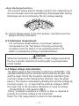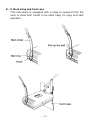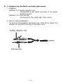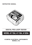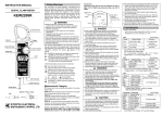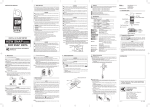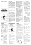
1
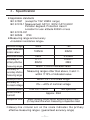
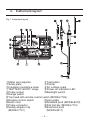
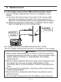
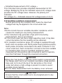
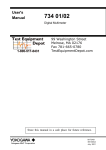
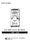
Instruction manual
Compact Insulation resistance tester with 2-range
KEW MEG series
MODEL3161A
KYORITSU ELECTRICAL INSTRUMENTS
WORKS,LTD.
Contents
1.Safety warnings ……………………………………………………1
2.Features ……………………………………………………………4
3.Specification ………………………………………………………5
4.Instrument layout …………………………………………………8
5.Preparation for measurement ……………………………………9
5−1 Mechanical zero adjustment ………………………………9
5−2 Test lead connection ………………………………………9
5−3 Battery voltage check ………………………………………10
5−4 Power-on-indication LED …………………………………10
6.Measurement ………………………………………………………11
6−1 AC voltage measurement …………………………………11
(Mains disconnection check)
6−2 Insulation resistance measurement ………………………12
6−3 Continuous measurement …………………………………14
6−4 Output voltage characteristics ……………………………14
6−5 Backlight function …………………………………………16
7.Battery replacement ………………………………………………16
8.Notes on Housing case and accessories ………………………17
8−1 Case lid ……………………………………………………17
8−2 Neck strap and Cord case …………………………………18
8−3 Test prods and replacement ………………………………19
8−4 Adaptors for the Earth cord and replacement …………20
8−5 Cleaning Meter cover ……………………………………21
1.Safety warnings
○ This instrument has been designed, manufactured and tested
according to IEC 61010-1: Safety requirements for Electronic
Measuring apparatus, and delivered in the best condition after
passed the inspection. This instruction manual contains
warnings and safety rules which must be observed by the user
to ensure safe operation of the instrument and retain it in safe
condition. Therefore, read through these operating instructions
before using the instrument.
WARNING
¡Read through and understand the instructions contained in this
manual before using the instrument.
¡Keep the manual at hand to enable quick reference whenever
necessary.
¡The instrument is to be used only in its intended applications.
¡Understand and follow all the safety instructions contained in
the manual.
It is essential that the above instructions are adhered to.Failure
to follow the above instructions may cause injury, instrument
damage and/or damage to equipment under test.
○ The symbol
indicated on the instrument, means that the user
must refer to the related parts in the manual for safe operation
of the instrument. It is essential to read the instructions
wherever the
symbol appears in the manual.
DANGER
WARNING
CAUTION
is reserved for conditions and actions that are
likely to cause serious or fatal injury.
is reserved for conditions and actions that can
cause serious or fatal injury.
is reserved for conditions and actions that can
cause injury or instrument damage.
―1―
DANGER
¡Never make measurement on a circuit in which the electrical
potential exceeds AC/DC600V(Measurement CAT. III 300V/CAT. II
600V).
¡Do not attempt to make measurement in the presence of flammable
gasses. Otherwise, the use of the instrument may cause sparking,
which can lead to an explosion.
¡Never attempt to use the instrument if it's surface or your hand are wet.
¡Be careful not to short-circuit the power line with the metal part of the
test leads when measuring a voltage. It may cause personal injury.
¡Do not exceed the maximum allowable input of any measuring range.
¡Never open the Battery cover during a measurement.
WARNING
¡Never attempt to make any measurement if any abnormal conditions,
such as a broken case or exposed metal parts are present on the
instrument and test leads.
¡Never press the Test button while connecting the test leads.
¡Never rotate the Range switch with the test leads connected to the
equipment under test.
¡Do not install substitute parts or make any modification to the
instrument. Return the instrument to your local KYORITSU distributor
for repair or re-calibration in case of suspected faulty operation.
¡Never touch the circuit under test during/immediately after the
insulation resistance measurement. The test voltage may cause
electrical shock.
¡Do not replace batteries if the instrument is wet.
¡Ensure that the test leads are firmly inserted into the terminal.
¡Set the Range switch to OFF position when opening the Battery
cover for battery replacement.
― 2 ―
CAUTION
¡Always set the Range switch to the appropriate position before
making measurement.
¡Set the Range switch to "OFF" position after use and remove the test
leads. The instrument consume small current at any range other
than OFF, and it shortens the battery life. Remove the batteries if the
instrument is to be stored and will not be in use for a long period.
¡Do not expose the instrument to direct sunlight, high temperatures,
humidity or dew.
¡Use a damp cloth with neutral detergent for cleaning the instrument.
Do not use abrasives or solvents.
¡Do not store the instrument if it is wet. Store it after it dries.
―3―
2.Features
MODEL3161A is a two-range insulation resistance tester for
testing various elevators and safety equipments.
¡Designed to following safety standards:
IEC 61010-1, IEC 61010-031, IEC 61557 (500V/ 100MΩ only)
¡Small and light weight.
¡Auto-discharge function
When insulation resistance like a capacitive load is measured,
electric charges stored in capacitive circuits are automatically
discharged after measuring. Discharge can be checked with the
meter.
¡Color-coded scales for easy and correct reading
¡Power-on indicator on insulation resistance and battery check
ranges.
¡Backlight function to facilitate working at dimly illuminated
location or at nighttime work.
¡AC voltage measurement function
¡Measures AC voltage on all ranges without pressing the Test
button
¡Test leads with remote control switch
(voltage won't be outputted when the test lead is not connected.)
¡Robust housing case
¡Neck strap for both hand's operation
¡User-changeable test prod
―4―
3.Specification
¡Applicable standards
IEC 61557 (except for 15V/ 20MΩ range)
IEC 61010-1 Measurement CAT.III 300V/ CAT.II 600V
Pollution degree2, Protection class II
Location for use: altitude 2000m or less
IEC 61010-031
IEC 60529
IP40
¡Measuring range and accuracy
<Insulation resistance range>
Nominal voltage
Max. effective
scale value
Mid-scale value
Accuracy in
primary effective
measuring ranges
Accuracy in
secondary effective
measuring ranges
Accuracy at 0 and ∞
Accuracy at
no-load voltage
Nominal current
Short-circuit
current
Response time
500V
15V
100MΩ
20MΩ
2MΩ
0.05MΩ
0.1∼
0.005∼
50MΩ
2MΩ
within ±5% of indicated value
Measuring ranges other than above, 0 and ∞.
within ±10% of indicated value
within ±0.7% of scale length
0%∼+20% of nominal voltage
1mA 0%∼+20%
Not specified
Approx. 2mA
Meter reading comes within accuracy within 3 sec.
(It may take time when measuring a capacitive load.
※Heavy-line circular arc on the scale indicates the primary
effective measuring ranges. (guaranteed accuracy range)
―5―
<Operating error>
Operating error (B) is an error obtained under the nominal operating
conditions, and calculated with the intrinsic error (A), which is an
error of the instrument used, and the error (En) due to variations.
According to IEC61557, the maximum operating error should be
within +/-30%.
B =︱A︱+ 1.15 × √
( E12 + E22 + E32 )
A : Intrinsic error (%)
B : Operating error (%)
E1: Variation due to changing the temperature (%)
E2: Variation due to changing the Battery voltage (%)
E3: Variation due to changing the position (%)
¡ Nominal operating conditions
Ambient temperature : 0 ∼ 40℃
Relative humidity
: 90% or less
External magnetic field : 400A/m or less
Position
: Horizontal ∼ ±90°
Battery voltage
: within "BATTERY. GOOD" range
< AC voltage range>
Measured voltage
Accuracy
0 ∼ 600V
within ±3% of the max. scale value
<Current consumption>(*Supply voltage: 6V)
Outputting
Mid-point
at shortStandRange
circuited nominal current measuremet
by
230mA
500V/100MΩ
170mA/0.5MΩ
85mA/2MΩ 55mA
230mA
15V/20MΩ
Not specified
Not specified 55mA
230mA
BATT.CHECK
Increased by 45mA
Using Back light
<Number of measurement>
Possible number of measurement within the "BATTERY.GOOD"
range.(Measure 5 sec., and take pause for 25 sec..)
Possible number
Resistor
Range
of measurement
for test
at least 700 times
15V/20MΩ
0.05MΩ
at least 700 times
500V/100MΩ
0.5MΩ
―6―
Temperature & humidity
range
Storage temperature &
humidity range
Insulation resistance
Withstand voltage
: 0℃ ∼ 40℃ (RH: 85% or less)
(no condensation)
: -20℃ ∼ +60℃ (RH: 75% or less)
(no condensation)
: at least 50MΩ/ DC500V between
the electrical circuit and the enclosure
: AC3700V(50/60Hz) for 1 min. between
the electrical circuit and the enclosure
Overload protection
Insulation resistance range:
15V
100V (50/60Hz) for 10 sec.
500V
600V (50/60Hz) for 10 sec.
AC voltage range:
600V
720V (50/60Hz) for 10 sec.
Dimension
: approx. 90(L) x 137(W) x 40(D)mm
Weight
: approx. 340g (including batteries)
Power source
: R6P (SUM-3), AA, x 4pcs
Nominal power
: 1.8VA
Accessories
MODEL7139 Test lead with remote control switch
MODEL7101 Flat test bar
MODEL7131 Safety alligator clip
MODEL8017 Extension prod
Neck strap
Cord case
R6P (SUM-3), size AA
Instruction manual
Optional
MODEL7116 Extension probe
MODEL8016 Pickle type prod
Pickle type prod
Extension probe
―7―
1 set
1 pce
1 pce
1 pce
1 pce
1 pce
4 pcs
1 pce
4.Instrument layout
Fig. 1 Instrument layout
①Meter zero adjuster
②Test button
③Scale plate
④Pointer
⑤Insulation resistance scale
⑥AC voltage scale
⑦"BATTERY-GOOD" range
⑧Power-on-indication LED
⑨Probe socket
⑩Backlight switch
⑪Range switch
⑫Test lead with remote control switch (MODEL7139)
⑬Remote control switch
⑭Line probe
⑮Earth cord
⑯Standard prod (MODEL8072)
⑰Probe connector
⑱Flat test bar (MODEL7101)
⑲Safety alligator clip
⑳Extension prod
(MODEL7131)
(MODEL8017)
―8―
5.Preparation for measurement
5-1 Mechanical zero adjustment
With the Range switch set to the OFF position and without
pressing the Test button, turn the Zero adjuster with a
screwdriver so that the pointer lines up with the "∞" mark on
an insulation resistance scale. In case the instrument is used
at the sloping place, ensure that the pointer lines up with the
"∞" mark tilting the instrument to the necessary angle.
5-2 Test lead connection
Insert the Probe connector into the Probe socket on the
instrument correctly as shown below.
DANGER
When the Test button or the Remote control switch is pressed
with the Range switch set to an insulation resistance range,
take care not to touch the tip of the Test probe where a high
voltage is present in order to avoid possible shock hazard.
CAUTION
Instrument doesn't operate without connecting the test lead
even if the Test button is pressed down. Battery check and
operation check are not available without connecting the test
lead. The Backlight function is available at any time.
―9―
5-3 Battery voltage check
(1) Connect the test lead to the instrument, and set the
Range switch to the BATT. CHECK position.
(2) Press the Test button or Remote control switch.
(3) If the meter pointer does not move to BATT GOOD, replace
the batteries as shown in Section 7 "Battery replacement".
Batteries have exhausted.
Replace the batteries.
Proceed to measurement.
CAUTION
Never keep the Test button pressed or locked during battery
check to avoid battery power drain.
5-4 Power-on-indication LED
On an insulation resistance range or BATT. CHECK range,
when the Test button or Remote control switch is pressed, the
power-on-indication LED (red) lights up, indicating the
instrument is in the operation mode.
― 10 ―
6.Measurement
6-1 AC voltage measurement (Mains disconnection check)
The AC voltage measurement function is available on any
ranges.
(1) Connect the Earth probe to the earth of the circuit under
test and Line probe to the other side. If the circuit is not
earthed, connect Earth probe to any appropriate conductor.
(2) Without pressing the Test button or Remote control switch,
take the reading on the AC voltage scale.
CAUTION
Never press
remote switch
CAUTION
Never press
test button
AC voltage measurement (Mains disconnection check)
The AC voltage measurement function is available on any ranges.
DANGER
¡Never make measurement on a circuit in which the electrical
potential exceeds AC/DC300V in order to avoid possible shock
hazard. (Refer to Section 3. "Specification, AC voltage
measurement.)
¡When testing installation that has a large current capacity, such
as a power line, be sure to make measurement on the
secondary side of a circuit breaker in order to avoid personal
injury.
¡Do not press the Test button or Remote control switch during
voltage measurement.
¡Never short live conductors with the tip of a probe to avoid
personal injury.
¡Do not make measurement with the Battery cover removed.
― 11 ―
< Simplified measurement of DC voltage >
This instrument also provides simplified measurement of DC
voltage. Multiplying 0.9 by the indicated value at AC voltage scale
provides the DC voltage value. However, the polarity isn't
indicated.
DC voltage (V) = Indicated value at AC voltage scale x 0.9 (V)
6-2 Insulation resistance measurement
Before performing any insulation test, check the maximum
voltage that may be applied to the circuit under test.
Note:
¡Some circuits have an unstable insulation resistance, which
causes the reading to vary during measurement.
¡The instrument may generate a high pitch tone during
measurement. This is not a failure.
¡If the circuit under test has a large capacitive load, it may take
some time before the final reading can be obtained.
¡On insulation resistance range, DC voltage is supplied through
Earth and Line probes, with Earth probe having positive polarity.
Earth probe should be connected to the earth conductor in the
circuit under test. Such connection is known to be more suitable
for insulation tests since an insulation resistance value
measured with the positive side connected to earth is typically
less than that taken through the reversed connection.
DANGER
¡When the Test button or Remote control switch is pressed with
the Range switch set to an insulation resistance range position,
take care not to touch the tip of the test probe or the circuit
under test where a high voltage is present in order to avoid
possible shock hazard.
¡Do not make measurement with the Battery cover removed.
CAUTION
Ensure that the circuit under test is de-energized prior to any
insulation testing.
― 12 ―
(1) Check the maximum voltage that may be applied to the circuit
under test. Set the Range switch to a desired insulation
resistance range.
(2) Connect Earth probe to the earth terminal of the circuit under
test. If the circuit is not earthed, connect Earth probe to any
appropriate conductor.
(3) Connect Line probe to the circuit under test and press the
Test button or Remote control switch.
(4) Take the reading on the scale for the selected insulation
resistance range.
Connect side Earth terminal
source side
Select range
Circuit breaker
CAUTION
Make sure to turn
Remote control switch Load side off the circuit
breaker.
Test button
Press the test button or remote control switch.
(5) Release the Test button or Remote control switch and leave
the probes connected to the circuit under test to discharge
charges stored in the capacitance of the circuit.
DANGER
¡Do not touch the circuit under test immediately after testing.
Charges stored in the capacitance of the circuit may cause
electrical shock.
¡Leave the probes connected to the circuit under test
until the pointer returns to the left end of the scale. Never touch
the circuit before the discharging completes.
― 13 ―
<Auto discharge function>
This function allows electric charges stored in the capacitance of
the circuit under test to be automatically discharged after testing.
Discharge can be monitored by the AC voltage reading.
(6) Set the Range switch to the OFF position, and disconnect the
probes from the instrument.
6-3 Continuous measurement
For continuous measurement, a lock-down feature is
incorporated on the Test button. Pressing and turning
clockwise locks the button in the operating position, the
button is released by turning it counterclockwise.
DANGER
While the Test button is locked down, a high voltage is present at
the tip of a probe. Attention should be paid to avoid possible
shock hazard.
6-4 Output voltage characteristics
The 500V range of this instrument conforms to IEC61557. This
standard defines that the nominal current shall be at least 1mA,
and the lower limit of the insulation resistance maintaining the
nominal voltage at the measurement terminal. (See the graph
below.) This value is calculated by dividing the nominal voltage by
nominal current. i.e., in case that the nominal voltage is 500V,
the lower limit of the insulation resistance is found as follows.
Divide 500V by 1mA equals 0.5MΩ
That is, insulation resistance of 0.5MΩ or more is required to
provide the nominal voltage to the instrument.
Note) The 15V range doesn't conform to this standard.
― 14 ―
M-3161A Output characteristics
― 15 ―
6-5 Backlight function
To facilitate working in dimly lit situations, a backlight function is
provided which illuminates the scale plate. Press the backlight
switch to operate this function. The backlight will light up for
about 30 sec., and then turned off automatically.
7.Battery replacement
DANGER
Never open the Battery cover during a measurement.
WARNING
To avoid possible electric shock, remove test leads before
opening the Battery cover. After replacing batteries, be sure
to tighten up the screws for Battery cover.
CAUTION
Do not mix new and old batteries.
Install batteries in correct polarity as marked inside the Battery
compartment.
― 16 ―
(1) Set the Range switch to "OFF" position, and remove the test
leads from the instrument.
(2) Loosen the Battery-cover-fixing screws, and remove the Battery
cover. Always replace all 4 batteries with new one at the same
time.
(3) After replacing batteries, be sure to tighten up the screws for
Battery cover.
Fixing-screws
Install batteries in correct
polarity as marked inside the
Battery compartment.
8.Notes on Housing case and accessories
8−1 Case lid
Case lid can be fit under the Housing case while making
measurement.
(1) Unhook and open the Case lid.
(2) Turn it 180 degrees.
(3) Put the Case lid under the Housing case.
(4) Hook it on to the Housing case.
― 17 ―
8−2 Neck strap and Cord case
This instrument is equipped with a strap to suspend from the
neck to allow both hands to be used freely for easy and safe
operation.
― 18 ―
8−3 Test prods and replacement
1. Types of Test prods
MODEL8072:Standard Test prod
Used for ordinary measurement.
(Attached to the Line probe at the time of
purchase.)
MODEL8017:Extension probe
Used in difficult-to-reach situations.
MODEL8016:Pickle prod (Optional)
Used to hook the probe on a conductor.
2. How to replace Test prod
To remove the Test prod, turn the cap of LINE probe
counterclockwise. Insert the threaded end of another prod
into the hexagonal hole on the probe cap as shown. Then,
turn the probe cap clockwise to secure it on the body of the
probe.
Male Screw
Female
Screw
Hexagonal Hole
Extension Prod
Prod
Pickel Prod
― 19 ―
8−4 Adaptors for the Earth cord and replacement
1. Adaptors
MODEL7131:Safety alligator clip
Connected to the Earth terminal of the Earth
terminal board.
MODEL7101:Flat test bar
Connected to the earth side of the outlet.
2. How to replace Adaptors
To remove the adaptors, pull them out. Then firmly attach the
adaptor as desired to the tip of the Earth cord.
Sefety alligator clip
Flat test bar
― 20 ―
8−5 Cleaning Meter cover
This instrument is managed by our company's quality standard
and is delivered in the best condition after passed the
inspection. But in the dry time of winter static electricity
sometimes builds up on the meter cover due to the
characteristic of plastic.
When static builds up on the meter cover and affects the meter
reading, use a cloth damped with off-the-shelf anti-static agent
or detergent to wipe the meter cover surface.
CAUTION
¡When the pointer deflects by touching the surface of this
instrument or zero adjustment cannot be made, do not try to
make measurement.
¡Antistatic agent has been applied to the meter cover of the
instrument for electrification prevention, therefore, do not rub it
strongly with a dry cloth etc. even if it is dirty.
¡ To avoid possible deforming or discoloring, do not use
solvents.
― 21 ―
DISTRIBUTOR
KYORITSU ELECTRICAL
INSTRUMENTS
WORKS, LTD.
No.5-20, Nakane 2−chome,Meguro-ku,
Tokyo, 152-0031 Japan
Phone:81−3−3723−0131 Fax:81−3−3723−0152
URL:http://www.kew-ltd.co.jp
E-mail:[email protected]
Factories:Uwajima & Ehime
04-08
92-1647