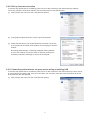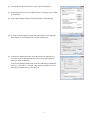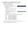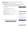
1
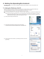
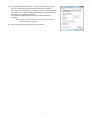
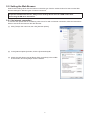
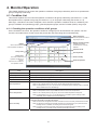
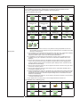
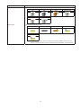
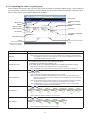
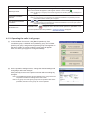
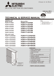
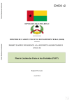
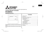
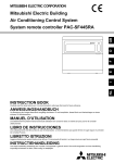
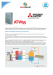
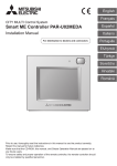
Air Conditioning Control System
Centralized Controller
EB-50GU-A/EB-50GU-J
Instruction Book
–Web Browser for User–
Contents
1. Introduction............................................................................2
1-1. Terms Used in This Manual..........................................................2
1-2. PC Requirements..........................................................................2
2. Setting the Operating Environment.......................................3
2-1. Setting the IP Address of the PC..................................................3
2-2. Setting the Web Browser..............................................................5
3. Logging in to the Web Browser for User................................8
4. Monitor/Operation................................................................10
4-1. Condition List..............................................................................10
Before using the controller, please read this Instruction Book carefully to ensure proper operation.
Retain this manual for future reference.
1.Introduction
Mitsubishi Electric Corporation’s Centralized Controller EB-50GU-A/EB-50GU-J features functions to allow users
to monitor and operate the air conditioning units from a PC over the LAN.
This Instruction Book explains how to monitor and operate the units connected to the EB-50GU-A/EB-50GU-J
using a Web browser.
1-1. Terms Used in This Manual
- "Centralized Controller EB-50GU-A/EB-50GU-J" is referred to as "EB-50."
- "Booster unit" and "Water HEX unit" are referred to as "Air To Water (PWFY) unit."
- Screen images used in this manual are from Windows 7 ® and Internet Explorer 9.0.
Note: Windows is a registered trademark or trademark of Microsoft Corporation in the United States and other countries.
1-2. PC Requirements
Table1-1 PC Requirements
Item
Requirement
CPU
1 GHz or faster
Memory
512 MB or more
Screen resolution
1024 x 768 or higher recommended
Windows
Microsoft ® Internet Explorer 8.0
Microsoft ® Internet Explorer 9.0
* J ava execution environment is required.
(Oracle ® Java Plug-in Ver. 1.7.0_11)
* Install Oracle ® Java Plug-in that is appropriate for your operating system. When
using a 64-bit Internet Explorer, install a 64-bit Java Plug-in.
* The version of the Oracle ® Java Plug-in can be verified by clicking [Java] in the
Control Panel.
Macintosh
Safari 6
* J ava execution environment is required.
(Oracle ® Java Plug-in Ver. 1.7.0_11)
* The version of the Oracle ® Java Plug-in can be verified by clicking [Help]-[Installed
Plug-ins] on the Safari browser.
Browser
On-board LAN port or LAN card
100 BASE-TX
Pointing device
e.g., mouse
Note: Microsoft is a registered trademark or trademark of Microsoft Corporation in the United States and/or other countries.
Oracle and Java are trademarks or registered trademarks of Oracle Inc. in the United States and/or other countries.
2
2.Setting the Operating Environment
This chapter explains how to make PC settings and Web browser settings to monitor and operate the air
conditioning units.
2-1. Setting the IP Address of the PC
Follow the instructions below to set the PC's IP address for the Web browser to recognize the EB-50 unit.
The PC's IP address must have the same network address as the EB-50's IP address.
(i.e., EB-50's IP address: [192.168.1.1], PC's IP address: [192.168.1.101])
When connecting an EB-50 to an existing LAN, consult the system administrator to decide the IP address of the
PC.
Note: When using an EB-50-dedicated LAN, it is recommended that the main EB-50 unit be assigned an IP address
between the range [192.168.1.1] and [192.168.1.40] and that the PC connected to the EB-50 be assigned an IP
address between the range [192.168.1.101] and [192.168.1.150].
(1) Click [Control Panel] in the Start menu.
(2) Click [Network and Sharing Center]>[Local Area Setting].
In the [Local Area Connection Status] window, click [Properties].
(3) Click [Internet Protocol Version 4 (TCP/IPv4)] to select it, and click
[Properties].
3
(4) In the [Internet Protocol Version 4 (TCP/IPv4) Properties] window,
check the radio button next to [Use the following IP address].
Enter the PC’s IP address (e.g., [192.168.1.101]) in the [IP address]
field, and enter the subnet mask [255.255.255.0] (unless otherwise
specified) in the [Subnet mask] field.
In the [Default gateway] field, enter the gateway address as
necessary.
Note: Consult the system administrator to decide the IP, subnet
mask, and gateway addresses.
(5) Keep clicking [OK] or [Close] to close all windows.
4
2-2. Setting the Web Browser
Web browser setting varies with the Internet connection type. See the sections below for how to make Web
browser settings for different types of Internet connection.
To prevent unauthorized access, always use a security device such as a VPN router when
connecting the EB-50 to the Internet.
2-2-1. No Internet connection
To monitor and operate the air conditioning units from a PC with no Internet connection, follow the instructions
below to set the environment for the Web browser.
(1) Click [Tools] in the menu bar, then click [Internet options].
(2) In the [Internet Options] window, click the [Connections] tab.
(3) Check the radio button next to [Never dial a connection] in the middle
of the window, and click [OK] to close the window.
5
2-2-2. Dial-up Internet connection
To monitor and operate the air conditioning units from a PC that connects to the Internet through a dial-up
connection, follow the instructions below to set the environment for the Web browser.
(1) Click [Tools] in the menu bar, then click [Internet options].
(2) In the [Internet Options] window, click the [Connections] tab.
(3) Check the radio button next to [Dial whenever a network connection
is not present] in the middle of the window, and click [OK] to close the
window.
By making these settings, a message will appear asking whether
or not to use a dial-up connection when an Internet connection is
necessary. Follow the message to connect to the Internet.
2-2-3. Connecting to the Internet via proxy server using an existing LAN
To monitor and operate the air conditioning units from a PC that connects to the Internet through a proxy server
by connecting to an existing LAN, such as a LAN within your company, follow the instructions below to set the
environment for the Web browser.
(1) Click [Tools] in the menu bar, then click [Internet options].
6
(2) In the [Internet Options] window, click the [Connections] tab.
(3) Check the radio button next to [Never dial a connection] in the middle
of the window.
(4) Click [LAN settings] under [Local Area Network (LAN) settings].
(5) In the [Local Area Network (LAN) Settings] window, check [Bypass
proxy server for local addresses], and click [Advanced].
(6) In the [Proxy Settings] window, enter the EB-50’s IP address (e.g.,
192.168.1.1) in the [Exceptions] field. Then, keep clicking [OK] or
[Close] to close all windows.
If connecting multiple EB-50 units, enter the addresses of all EB-50
units (e.g., [192.168.1.1; 192.168.1.2]). It is also possible to use an
asterisk as a wildcard (e.g., [192.168.1.*]).
7
3.Logging in to the Web Browser for User
(1) Enter the web page address in the address field of the Web browser as follows:
http://[IP address of the EB-50]/index.html
Press the [Enter] key. A login screen will appear.
Note: If the IP address of the EB-50 is [192.168.1.1], the web page
address is [http://192.168.1.1/index.html].
Note: Default IP address of EB-50 is [192.168.1.1].
Note: If the login screen does not appear then take the steps below
to delete the temporary files.
<Internet Explorer>
1. Click [Tools] in the menu bar, then click [Internet options].
2. On the [General] tab, click [Delete] in the middle of the
window.
3. In the [Delete Browsing History] window, click [Delete].
<Java>
1. Click [Control Panel] from the Start menu.
2. C
lick the [Java] icon to launch the Java Control Panel.
3. O
n the [General] tab, click [Settings] in the [Temporary
Internet Files] section.
4. C
lick [Delete Files].
5. In the [Delete Files and Applications] window, click [OK].
Note: The web page will be displayed in the same language as the operating system on the PC.
The web page can be displayed in other languages by entering the web page address as follows:
Chinese
English
French
German
Italian
Japanese
Portuguese
Russian
Spanish
http://[IP address of the EB-50]/zh/index.html
http://[IP address of the EB-50]/en/index.html
http://[IP address of the EB-50]/fr/index.html
http://[IP address of the EB-50]/de/index.html
http://[IP address of the EB-50]/it/index.html
http://[IP address of the EB-50]/ja/index.html
http://[IP address of the EB-50]/pt/index.html
http://[IP address of the EB-50]/ru/index.html
http://[IP address of the EB-50]/es/index.html
Note: You can add the web page address to your Favorites for easy access in the future.
(2) Enter the user name and the password in the login screen, and click [Login]. A Condition List screen will
appear, which shows the operation conditions of all groups.
Note: Consult the building manager for your user name and password.
8
Encrypting the communication data and logging in to the Web browser
(HTTPS connection)
EB-50 can encrypt communication data using HTTPS (SSL).
When connecting the EB-50 to the LAN that is accessible to the general public, it is recommended that the
following settings be made so that the units are monitored and controlled on the encrypted web page.
Note: Depending on the operating system or the Java version, HTTPS encrypted communication may not be enabled
properly. If this happens, use an HTTP connection as explained in the previous page.
(1) Prefix the web address with [https], enter the rest of the address, and
press the [Enter] key.
https://[IP Address of the EB-50]/index.html
Note: If the IP address of the EB-50 is [192.168.1.1], the web page address is
[https://192.168.1.1/index.html].
The encrypted data communication will begin, and the Login screen
will appear.
If a security certificate error page appears instead of the Login
screen, go to step (2) below.
(2) If the security certificate is invalid, a security certificate error page (as
shown at right) will appear.
Click [Continue to this website (not recommended)].
(3) If the connection is successfully made, the Login screen will appear.
Note: Although the address bar will turn red and a message "Certificate
error" will appear, you can still access the Web browser.
9
4.Monitor/Operation
This chapter explains how to monitor the operation conditions of all groups collectively and how to operate each
group or all groups collectively.
4-1. Condition List
This section explains how to monitor the operation conditions of all groups collectively (see section 4-1-1) and
also explains how to operate each group (see section 4-1-2), or all groups collectively (see section 4-1-3).
After login, a Condition List screen will appear, which shows the operation conditions of all air conditioning unit
groups, LOSSNAY unit (ventilator) groups, general equipment groups, and Air To Water (PWFY) unit groups.
4-1-1. Checking the operation conditions of all groups
On the Condition List screen, the operation conditions of all groups can be monitored. The operator can also
check the unit malfunctions on this screen and prevent the units from being left on unintentionally.
Batch Operations
Click to operate the units in
all groups at once.
Weekly schedule number
Indicates the weekly
schedule that is currently
effective.
Update
Click to show the most
recent operation conditions.
Operation mode
Group name
Set temperature
Group icons
The icons indicate the
operation conditions of
groups.
Click the icon to switch to
the operation screen.
Room humidity
Room temperature
Item
Description
Update
Click to show the most recent operation conditions.
Batch Operations
Click to operate the units in all groups at once. (See section 4-1-3.)
Group name
The name of the group will appear.
Operation mode
The operation mode of the group will appear.
The set temperature of the group will appear.
Set temperature
Note: For Air To Water (PWFY) unit groups, the set water temperature will appear.
Note: The temperature unit (°C or °F) can be set on the Basic System settings screen, accessible
via the Web Browser for Initial Settings.
Indoor unit return air temperature will appear.
Room temperature
Note: The temperature shown may be different from the actual room temperature.
Note: For Air To Water (PWFY) unit groups, the current water temperature will appear.
Note: The temperature unit (°C or °F) can be selected on the Basic System settings screen,
accessible via the Web Browser for Initial Settings.
The reading of the indoor unit return air humidity or the humidity sensor on the ME remote
controller (Smart ME controller) will appear.
Room humidity
Note: The value will not appear if the indoor unit does not have a humidity measurement function.
Note: If a ME remote controller (Smart ME controller) is connected to the group and the built-in
humidity sensor is enabled, the reading of the sensor will appear.
Note: The indoor unit return air humidity has priority to be displayed over the reading of the
humidity sensor on the ME remote controller (Smart ME controller).
10
Item
Description
Each group icon indicates the operation condition of the group. Move the cursor to the
icon to display its group name. Clicking the icon will bring up the operation screen.
The icons to indicate the operation conditions are shown below.
(1) Air conditioning unit group
ON
OFF
Error
Filter sign ON
Interlocked
LOSSNAY ON
Interlocked
LOSSNAY OFF
Schedule set
HOLD ON
Energy-saving ON
Setback ON
Starting up
Occupied/Vacant
*1
*2
*3*4*5
(Blue)
(Gray)
Bright/Dark
*6*7*8
(Yellow)
Group icons
(Gray)
Note: Besides the 4-way airflow unit icons, 2-way airflow or ceiling-suspended unit icons are
also available. Icons can be selected on the group settings screen, accessible via the Web
Browser for Initial Settings.
*1 If the LOSSNAY unit is interlocked with the operation of Mr. Slim units, "Interlocked LOSSNAY
ON" icon will appear, even when the LOSSNAY unit is operated individually.
(Applicable M-NET adapter model: PAC-SF48/50/60/70/80/81MA-E)
*2 If a LOSSNAY unit is interlocked with the operation of indoor units in multiple groups, the
LOSSNAY unit may be in operation, even when the "Interlocked LOSSNAY OFF" icon is
displayed.
*3 The Occupancy/Vacancy status icon will appear only when [Show occupancy icon], [Show
vacancy icon], or [Show both icons] is selected in the [Occupancy sensor display] section
under the [Display Format] section of the Basic System settings screen, accessible via the
Web Browser for Initial Settings.
*4 The Occupancy/Vacancy status icon will not appear if the remote controller in the group does
not have an occupancy sensor.
*5 The Occupancy/Vacancy status icon takes priority over the "Interlocked LOSSNAY ON" or
"Interlocked LOSSNAY OFF" icon.
*6 The Brightness/Darkness status icon will appear only when [Show bright symbol], [Show dark
symbol], or [Show both symbols] is selected in the [Brightness sensor display] section under
the [Display Format] section of the Basic System settings screen, accessible via the Web
Browser for Initial Settings.
*7 The Brightness/Darkness status icon will not appear if the remote controller in the group does
not have a brightness sensor.
*8 The "Setback ON" icon takes priority over the Brightness/Darkness status icon.
(2) LOSSNAY unit (ventilator) group
ON
OFF
Error
Schedule set
HOLD ON
Energy-saving ON
11
Filter sign ON
Item
Description
(3) Air To Water (PWFY) unit group
Group icons
ON
OFF
HOLD ON
Energy-saving ON
Error
Schedule set
Error
Schedule set
(4) General equipment group
ON
OFF
HOLD ON
Note: Besides the lighting icons, pump or card key icons are also available. The icon can be
selected on the group settings screen, accessible via the Web Browser for Initial Settings.
12
4-1-2. Operating the units in a given group
In the Condition List screen, click one of the group icons to display its operation settings screen, which shows the
current operation conditions. Change the desired settings and click [OK] to reflect the changes. Click [Cancel] to
return to the previous screen without making any changes.
Group name
"Centrally Controlled"
mark
Interlocked LOSSNAY
ON/OFF
Block name
ON/OFF
Operation mode
Fan speed
Set temperature
Air direction
Fan speed of interlocked
LOSSNAY
Filter Sign Reset
OK
Click to reflect the changes
made.
Cancel
Click to return to the
previous screen without
making any changes.
Item
Description
Click [ON] or [OFF] to turn on or off the units in a given group.
ON/OFF
Operation mode *1
Note: Switching this switch will turn on or off the LOSSNAY unit as well that is interlocked with
the operation of indoor units in the group. To turn on or off the LOSSNAY unit only, use the
"Interlocked LOSSNAY ON/OFF" switch.
Click the desired operation mode.
Air conditioning unit: Cool, Dry, Fan, Heat, Auto, Setback
LOSSNAY unit: Heat Recovery, Bypass, Auto
Air To Water (PWFY) unit: Heating, Heating ECO, Hot Water, Anti-freeze, Cooling
Note: Only the operation modes available for the unit model will appear.
Note: The Setback mode can be selected on the EB-50GU-A, but not on the EB-50GU-J.
Click
or
to adjust the set temperature of the air conditioning unit or the Air To
Water (PWFY) unit.
Set temperature *1
Note: The settable temperature ranges depend on the unit model.
Note: If the indoor unit supports the dual set point function in the AUTO mode and when the
operation mode above is set to Auto or Setback, two set temperatures for Cool mode and
Heat mode can be set.
Note: The temperature range restrictions settings on the Set Temperature Range Limit settings
screen on the Web Browser for Initial Settings will be effective on this screen.
Note: The temperature unit (°C or °F) can be selected on the Basic System settings screen,
accessible via the Web Browser for Initial Settings.
Click
or
(Mid 3)
to adjust the air direction.
(Mid 2)
(Mid 1)
(Mid 0)
(Horizontal)
Air Direction *1
Note: Available air directions depend on the unit model.
Click
or
(Low)
to adjust the fan speed.
(Mid 2)
(Mid 1)
(High)
Fan Speed *1
Note: Available fan speeds depend on the unit model.
13
(Auto)
(Swing)
(Auto)
Item
Filter Sign Reset
Interlocked LOSSNAY
ON/OFF
Fan speed of interlocked
LOSSNAY
Prohibition icon
Description
Click [Reset] to switch between resetting and not resetting the filter sign. The rectangular
icon next to Reset will appear in yellow-green when it is set to Reset ( ).
Note: If a filter sign in the group has not been triggered, then the item [Filter Sign Reset] will not
appear.
Click [ON] or [OFF] to turn on or off the interlocked LOSSNAY unit.
Note: For a group that is not connected to an interlocked LOSSNAY unit (ventilator), the item
[Interlocked ventilator ON/OFF] will not appear.
Click
or
to adjust the fan speed of the interlocked LOSSNAY unit (ventilator).
Note: For a group that is not connected to an interlocked LOSSNAY unit, the item [Fan speed of
interlocked LOSSNAY] will not appear.
Prohibition icon
will appear next to the item whose operation is prohibited. If one
or more operation items are prohibited,
*1 The item may not be displayed, depending on the unit model.
4-1-3. Operating the units in all groups
(1) In the Condition List screen, click [Batch Operations]. If air
conditioner group, LOSSNAY unit (ventilator) group, Air To Water
(PWFY) unit group, and general equipment group exist together in
the same system, a screen to select a group type will appear.
Click one of the group types to change its settings.
(2) On the operation settings screen, change the desired settings and
click [OK] to reflect the changes.
Click [Cancel] to return to the previous screen without making any
changes.
Note: The settable temperature range is limited for the group whose set
temperature restrictions settings have been made.
Note: If any group out of the given groups has an operation item that is
prohibited, the item for the group can not be operated.
14
will appear.
15
This product is designed and intended for use in the residential,
commercial and light-industrial environment.
The product at hand is based on the following EU regulations:
• Electromagnetic Compatibility Directive 2004/108/EC
• Restriction of Hazardous Substances 2011/65/EU
Please be sure to put the contact address/telephone number
on this manual before handing it to the customer.
HEAD OFFICE: TOKYO BLDG., 2-7-3, MARUNOUCHI, CHIYODA-KU, TOKYO 100-8310, JAPAN
WT06536X01