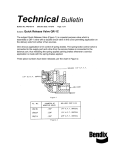
1
Pipeline Online Permitting System (POPS) User Guide Railroad Commission of Texas Information Technology Services Division August 21, 2015 Table of Contents Table of Contents .................................................................................................................... 3 Table of Figures ....................................................................................................................... 7 Pipeline Online Permitting System (POPS) Basics .................................................................. 11 POPS Screens Overview—Operator ....................................................................................... 12 Log In ....................................................................................................................................................... 12 Navigating the Pipeline Online Permitting Website ............................................................................... 13 Left Navigation Menu ......................................................................................................................... 13 List Navigation ..................................................................................................................................... 13 About the Dashboard .......................................................................................................................... 15 Search for Permits and Filings ............................................................................................................. 17 T-4 Permit and System Search ........................................................................................................ 17 T-4 Permit Filings Search ................................................................................................................. 20 Filtering Search Results ................................................................................................................... 23 Initial T-4 Permit Screens .................................................................................................................... 23 About the Permit Header Tab ......................................................................................................... 24 About the System/Segment Tab ..................................................................................................... 26 About the Attachments Tab ............................................................................................................ 27 About the Mapping Tab .................................................................................................................. 28 About the Certify/Submit Tab ......................................................................................................... 30 About the Amendment Info Tab ..................................................................................................... 30 About the Event Log Tab ................................................................................................................. 31 About the Merge Information Tab .................................................................................................. 32 POPS Screens Overview—Internal ......................................................................................... 34 About the Comments Tab ............................................................................................................... 34 About the Review Tab ..................................................................................................................... 34 Apply for a New T-4 Permit ................................................................................................... 36 Complete the Permit Header Tab ........................................................................................................... 36 Complete the System/Segment Tab ....................................................................................................... 38 Complete the Attachments Tab .............................................................................................................. 42 Complete the Mapping Tab .................................................................................................................... 43 Page 3 Complete the Certify/Submit Tab ........................................................................................................... 44 Verify Your Application Submission ........................................................................................................ 45 View PDF ............................................................................................................................... 47 View an Existing T-4 Permit ................................................................................................... 49 Edit an Application ................................................................................................................ 51 Renew, Inactivate, or Reactivate Filing for Existing T-4 Permit .............................................. 53 Renew a T-4 Permit ................................................................................................................................. 53 Inactivate a T-4 Permit ............................................................................................................................ 57 Reactivate a T-4 Permit ........................................................................................................................... 59 Amend an Existing T-4 Permit ................................................................................................ 60 Merge an Existing T-4 Permit or System ................................................................................ 62 Merge One or More T-4 Permits............................................................................................................. 62 Merge One or More Systems .................................................................................................................. 63 Transfer an Existing T-4 Permit, System, or Segment ............................................................. 66 Operator .................................................................................................................................................. 66 Supervisor ............................................................................................................................................... 66 Transfer a Permit ................................................................................................................................ 66 Transfer a System................................................................................................................................ 70 Transfer a Segment ............................................................................................................................. 71 Review T-4 Permit Applications—Internal ............................................................................. 74 About Reviewer Roles ............................................................................................................................. 74 About the Work Queue ........................................................................................................................... 74 Approve or Reject a T-4 Permit Application ........................................................................................... 75 About the 15-Day Window ................................................................................................................. 75 About the 45-Day Window ................................................................................................................. 76 Permitting Reviewer ........................................................................................................................... 76 Tools for Review and Validation ..................................................................................................... 77 Mapping Reviewer .............................................................................................................................. 83 POPS Tools for Review and Validation ............................................................................................ 84 GIS Tools for Review and Validation ............................................................................................... 88 GIS Workflow for Mapping Reviewers .......................................................................................... 104 Page 4 Gas Services Reviewer ...................................................................................................................... 109 Tools for Review and Validation ................................................................................................... 109 The Supervisor Role .......................................................................................................................... 114 The Supervisor as a Reviewer ....................................................................................................... 114 Simple Transfers............................................................................................................................ 115 Appendix A: Editing with ArcMap ........................................................................................ 123 A Quick Tour of Editing ......................................................................................................................... 123 Editor Toolbar ................................................................................................................................... 123 Create Features Window .................................................................................................................. 123 Template Properties Dialog Box ....................................................................................................... 124 Snapping Toolbar .............................................................................................................................. 125 Attributes Window ............................................................................................................................ 125 Edit Sketch Properties Window ........................................................................................................ 126 Editing Options Dialog Box ................................................................................................................ 127 Starting an Edit Session (Start Editing).............................................................................................. 127 Stopping an Edit Session (Stop Editing) ............................................................................................ 128 About Snapping ................................................................................................................................. 128 Enabling Snapping ............................................................................................................................. 130 Disabling Snapping ............................................................................................................................ 131 Turning on SnapTips .......................................................................................................................... 131 Setting the Snapping Tolerance ........................................................................................................ 132 Setting the Color Used for the Snap Symbol..................................................................................... 132 Using Select By Attributes ................................................................................................................. 132 Field Display Options in the Select By Attributes Dialog Box ............................................................ 134 Displaying a Subset of Features in a Layer ........................................................................................ 134 Creating a Definition Query .......................................................................................................... 135 Selecting Features While Editing ...................................................................................................... 135 Selecting Features With the Edit tool Compared With Other Selection Tools ................................. 136 Deleting a Feature ............................................................................................................................. 137 About Editing Attributes ................................................................................................................... 137 Editing Attributes in the Attributes Window ................................................................................ 137 Page 5 Keyboard Shortcuts in the Attributes Window ............................................................................. 139 Editing Attributes in the Table Window ........................................................................................ 139 Editing Values in a Table ................................................................................................................... 139 Editing Values in the Table Window ............................................................................................. 139 Copying and Pasting Records in Multiple Cells ............................................................................. 140 Editing Values in the Attributes Window .......................................................................................... 141 Editing Attributes in the Attributes Window .................................................................................... 142 Setting the Direction Type And Units Used When Editing ................................................................ 143 About Direction Measuring Systems and Units ............................................................................ 143 Direction Measuring Systems ....................................................................................................... 143 Direction Measuring Units ............................................................................................................ 145 Setting the Ground to Grid Correction ............................................................................................. 146 Adding a Segment to a Traverse Using a Direction-Distance Course ............................................... 146 Starting a Traverse From a Known Coordinate ............................................................................. 146 Calculating Area, Length, and Other Geometric Properties ............................................................. 147 Page 6 Table of Figures Figure 1: RRC Online System Screen ........................................................................................................... 12 Figure 2: Navigating a List ........................................................................................................................... 14 Figure 3: Pipeline Permit Application Dashboard ....................................................................................... 15 Figure 4: Pipeline Permit Application Dashboard Functions ...................................................................... 16 Figure 5: Filtering Dashboard Items ............................................................................................................ 17 Figure 6: The T-4 Permit and System Search Tab ....................................................................................... 17 Figure 7: Search for Operator ..................................................................................................................... 19 Figure 8: Search T-4 Permit Information and System Information ............................................................. 19 Figure 9: View Search Results on the T-4 Permit and System Search Screen ............................................. 20 Figure 10: The T-4 Permit Filings Search Screen ......................................................................................... 20 Figure 11: Search for Operator ................................................................................................................... 22 Figure 12: Search T-4 Permit Information and System Information ........................................................... 22 Figure 13: Filings Search Results ................................................................................................................. 23 Figure 14: Filtering Search Results .............................................................................................................. 23 Figure 15: The Permit Header Tab .............................................................................................................. 24 Figure 16: The System/Segment Tab .......................................................................................................... 26 Figure 17: The Attachments Tab ................................................................................................................. 28 Figure 18: The Mapping Tab ....................................................................................................................... 29 Figure 19: The Certify/Submit Tab .............................................................................................................. 30 Figure 20: The Amendment Info Tab .......................................................................................................... 31 Figure 21: The Event Log Tab ...................................................................................................................... 32 Figure 22: The Merge Information Tab ....................................................................................................... 33 Figure 23: The Comments Tab .................................................................................................................... 34 Figure 24: The Review Tab .......................................................................................................................... 35 Figure 25: Applying for a New T-4 Permit, Step 1 ....................................................................................... 36 Figure 26: Applying for a New T-4 Permit, Step 2 ....................................................................................... 37 Figure 27: Saving Your Progress .................................................................................................................. 37 Figure 28: Entering System Information ..................................................................................................... 39 Figure 29: Required Fields........................................................................................................................... 40 Figure 30: The Add Segment Button ........................................................................................................... 40 Figure 31: Adding Segment Information ..................................................................................................... 41 Figure 32: A Completed System/Segment Tab ........................................................................................... 41 Figure 33: Completing the Attachments Tab .............................................................................................. 42 Figure 34: Completing the Mapping Tab .................................................................................................... 44 Figure 35: Completing the Certify/Submit Tab ........................................................................................... 45 Figure 36: Verifying the Application Submission ........................................................................................ 46 Figure 37: Viewing a PDF ............................................................................................................................ 47 Figure 38: Example of a T-4 Application PDF .............................................................................................. 48 Figure 39: Viewing an Existing Permit ......................................................................................................... 49 Figure 40: View an Existing T-4 Permit ....................................................................................................... 50 Page 7 Figure 41: The Filing Status Column ............................................................................................................ 51 Figure 42: Editing an Application ................................................................................................................ 52 Figure 43: A T-4 Permit’s Dates................................................................................................................... 53 Figure 44: Renewing a T-4 Permit ............................................................................................................... 54 Figure 45: Renew a T-4 Permit, Steps 4 to 7 ............................................................................................... 55 Figure 46: Renew a T-4 Permit, Steps 9 to 13 ............................................................................................. 56 Figure 47: Renew a T-4 Permit Filing Type Updated................................................................................... 56 Figure 48: Inactivating a T-4 Permit ............................................................................................................ 57 Figure 49: Viewing a Permit after Inactivating ........................................................................................... 58 Figure 50: Viewing Permit Status on the Dashboard .................................................................................. 58 Figure 51: Reactivating a Permit ................................................................................................................. 59 Figure 52: Amending a T-4 Permit, Steps 1 – 3 ........................................................................................... 60 Figure 53: Amend a Permit, Steps 5 – 9 ...................................................................................................... 61 Figure 54: Merge One or More T-4 Permits, Steps 1 and 2 ........................................................................ 62 Figure 55: Merge One or More T-4 Permits, Steps 3 to 8 ........................................................................... 63 Figure 56: Merge a System Steps 1 and 2 ................................................................................................... 64 Figure 57: Merge a System, Steps 3 to 8 .................................................................................................... 65 Figure 58: Transfer a Permit, Steps 1 and 2 ................................................................................................ 66 Figure 59: Transfer a Permit, Step 4 ........................................................................................................... 67 Figure 60: Transfer a Permit, Steps 5 and 6 ................................................................................................ 67 Figure 61: Transfer a Permit, Steps 7 and 8 ................................................................................................ 68 Figure 62: Transfer a Permit, Step 10 ......................................................................................................... 69 Figure 63: Transfer a System, Steps 4 to 6 .................................................................................................. 70 Figure 64: Transfer a System, Steps 7 and 8 ............................................................................................... 70 Figure 65: Transfer a System, Steps 10 and 11 ........................................................................................... 71 Figure 66: Transfer a Segment, Steps 2 and 3 ............................................................................................ 72 Figure 67: Transfer a Segment, Steps 4 to 6 ............................................................................................... 72 Figure 68: Transfer a Segment, Steps 7 to 10 ............................................................................................. 73 Figure 69: Transfer Segment, Steps 11 to 12 .............................................................................................. 73 Figure 70: Permitting Reviewer Work Queue ............................................................................................. 76 Figure 71: Permitting Reviewer Steps 1 and 2 ............................................................................................ 77 Figure 72: Permitting Review: Header Tab ................................................................................................. 78 Figure 73: Permitting Reviewer System/Segment Tab ............................................................................... 79 Figure 74: Permitting Reviewer Attachments Tab ...................................................................................... 79 Figure 75: Permitting Reviewer Amendment Info Tab ............................................................................... 80 Figure 76: Permitting Reviewer Comments Tab ......................................................................................... 80 Figure 77: Permitting Reviewer Review Tab ............................................................................................... 81 Figure 78: Permitting Reviewer Work Queue Showing Filing Status Update ............................................. 82 Figure 79: Mapping Reviewer Workflow .................................................................................................... 83 Figure 80: Mapping Reviewer Work Queue................................................................................................ 84 Figure 81: Mapping Reviewer Steps 1 and 2............................................................................................... 84 Figure 82: Mapping Review: Header Tab .................................................................................................... 85 Page 8 Figure 83: Mapping Reviewer Mapping Tab ............................................................................................... 86 Figure 84: Mapping Reviewer Comments Tab ............................................................................................ 86 Figure 85: Mapping Reviewer Review Tab .................................................................................................. 87 Figure 86: Mapping Reviewer Work Queue Showing Filing Status Update ................................................ 88 Figure 87: The Summary Report ................................................................................................................. 91 Figure 88: The Validation Detail Report ...................................................................................................... 93 Figure 89: The Workflow Manager Tool .................................................................................................... 95 Figure 90: The Validate All Tool .................................................................................................................. 97 Figure 91: The Validate All Complete Dialog Box ........................................................................................ 97 Figure 92: The Validate Fields Tool ............................................................................................................. 98 Figure 93: The Validate Fields Completed Dialog Box ................................................................................ 98 Figure 94: The Validate Projection Tool ...................................................................................................... 99 Figure 95: The Validate Projection Completed Dialog Box ......................................................................... 99 Figure 96: The Validate Coordinates Tool ................................................................................................. 100 Figure 97: The Validate Coordinates Completed Dialog Box .................................................................... 100 Figure 98: The Validate Mileage Tool ....................................................................................................... 101 Figure 99: The Validate Mileage Completed Dialog Box ........................................................................... 101 Figure 100: The Validation Report Button ................................................................................................ 102 Figure 101: The Summary Report Button ................................................................................................. 102 Figure 102: The Workflow Manager Button ............................................................................................ 102 Figure 103: The TPMS Copy Tool .............................................................................................................. 103 Figure 104: The Upload to TPMS Tool ...................................................................................................... 103 Figure 105: Filter a Summary Report—Initial Validation Complete ......................................................... 105 Figure 106: Update Status in the Workflow Manager Tool ..................................................................... 105 Figure 107: Open the Application in POPS ................................................................................................ 106 Figure 108: Filter the Summary Report .................................................................................................... 107 Figure 109: Review the Validation Report ................................................................................................ 107 Figure 110: Open the Application in POPS ................................................................................................ 108 Figure 111: Gas Services Reviewer Work Queue ...................................................................................... 109 Figure 112: Gas Services Reviewer Steps 1 and 2 ..................................................................................... 110 Figure 113: Gas Services Review: Header Tab .......................................................................................... 110 Figure 114: Gas Services Reviewer System/Segment Tab ........................................................................ 111 Figure 115: Gas Services Reviewer Attachments Tab ............................................................................... 111 Figure 116: Gas Services Reviewer Amendment Info Tab ........................................................................ 112 Figure 117: Gas Services Reviewer Comments Tab .................................................................................. 112 Figure 118: Gas Services Reviewer Review Tab ........................................................................................ 113 Figure 119: Gas Services Reviewer Work Queue Showing Filing Status Update ...................................... 114 Figure 120: Supervisor Work Queue ......................................................................................................... 115 Figure 121: Permit Transfer, Steps 1 and 2 ............................................................................................... 116 Figure 122: Permit Transfer, Step 3 .......................................................................................................... 116 Figure 123: Permit Transfer, Steps 4 – 6 ................................................................................................... 117 Figure 124: Permit Transfer, Step 7 .......................................................................................................... 117 Page 9 Figure 125: Permit Transfer, Step 8 .......................................................................................................... 118 Figure 126: Supervisor System Transfer, Steps 1 and 2 ............................................................................ 119 Figure 127: Supervisor System Transfer, Step 3 ....................................................................................... 119 Figure 128: Supervisor System Transfer, Steps 4 and 5 ............................................................................ 120 Figure 129: Supervisor System Transfer, Steps 7 and 8 ............................................................................ 120 Figure 130: Supervisor System Transfer, Step 9 ....................................................................................... 121 Figure 131: Supervisor Segment Transfer, Steps 1 and 2 ......................................................................... 121 Figure 132: Supervisor Segment Transfer, Steps 3 and 4 ......................................................................... 122 Figure 133: Supervisor Segment Transfer, Steps 5 and 6 ......................................................................... 122 Figure 134: ArcMap Editor Toolbar........................................................................................................... 123 Figure 135: ArcMap Create Features Window.......................................................................................... 124 Figure 136: ArcMap Template Properties Dialog Box ............................................................................... 125 Figure 137: ArcMap Snapping Toolbar ..................................................................................................... 125 Figure 138: ArcMap Attributes Window ................................................................................................... 126 Figure 139: ArcMap Edit Sketch Properties Window ................................................................................ 126 Figure 140: ArcMap Editing Options Dialog Box ....................................................................................... 127 Figure 141: ArcMap Snapping ................................................................................................................... 129 Figure 142: ArcMap Snapping to a Vertex ................................................................................................ 129 Figure 143: ArcMap Snap to an Endpoint ................................................................................................. 130 Figure 144: ArcMap Select By Attributes Dialog Box ................................................................................ 133 Figure 145: ArcMap Specify Selection Method......................................................................................... 133 Figure 146: ArcMap Field Display Options ................................................................................................ 134 Figure 147: ArcMap Create a Definition Query ........................................................................................ 135 Figure 148: ArcMap Layer Properties Fields Tab ...................................................................................... 138 Figure 149: ArcMap Table Window .......................................................................................................... 140 Figure 150: Copying Excel Data into an ArcMap Table ............................................................................. 141 Figure 151: Pasting Excel Data into an ArcMap Table .............................................................................. 141 Figure 152: The ArcMap Attributes Window ............................................................................................ 142 Figure 153: ArcMap Polar Angles .............................................................................................................. 144 Figure 154: ArcMap North Azimuth .......................................................................................................... 144 Figure 155: ArcMap South Azimuth .......................................................................................................... 144 Figure 156: ArcMap Quadrant Bearing ..................................................................................................... 145 Page 10 Texas RRC Pipeline Online Permitting System User Guide Pipeline Online Permitting System (POPS) Basics The purpose of this document is to describe the steps users will take to use the Texas Railroad Commission’s Pipeline Online Permitting (POPS) Application. This application is developed for use by both RRC regulated communities as well as internal agency staff members. TIP: For the best viewing results, see the Browser Recommendations below. This web browser-based application allows the regulated community to electronically submit initial Pipeline T-4 Permit Applications (Form T-4), Pipeline T-4 Permit Amendments (including changes in mileage, characteristics changes, etc.), Pipeline System Additions, Pipeline T-4 Permit Inactivations, and Pipeline T-4 Permit Renewals. It will also provide for generation of Pipeline T-4 Permit Approval Letters when a Pipeline T-4 Permit is approved for an Operator in the system. Finally, the project will allow the public and other state agency personnel to access documents that have been submitted electronically, as well as reports based on Pipeline T-4 Permit data. TIP: Blue hyperlinks in this document are live links; they will take you directly to the named portion of the document. Browser Recommendations Internet Explorer 11.0+ and Google Chrome 39.0+ are recommended for the best viewing results. IMPORTANT: POPS does not display correctly in Compatibility View in Internet Explorer. To turn off Compatibility View, click the Compatibility View button in the Internet Explorer address bar. Internet Explorer 10.0 and below are not recommended. JavaScript must be enabled. Pop-up blocking in your browser must be disabled. TIP: To verify that pop-up blocking is disabled on your computer, use our Pop-up Blocker Test. Page 11 Texas RRC Pipeline Online Permitting System User Guide POPS Screens Overview—Operator Log In To access the Pipeline Online Permitting website, navigate to the following web address: https://webapps.rrc.state.tx.us/security/login.do. On the RRC Online System screen, click the Pipeline Online Permitting link, as depicted in Figure 1 below. Figure 1: RRC Online System Screen Page 12 Texas RRC Pipeline Online Permitting System User Guide Navigating the Pipeline Online Permitting Website There are many ways of getting around the Pipeline Online Permitting website, and this section describes the navigational menus that will help you get to where you want to go. Left Navigation Menu The left-hand navigation menu allows you to go to different pages in the Railroad Commission of Texas’ website. You can move to these new sections by clicking on one of the following links: 1. Home – Click the Home link to go to the RRC Online System page. 2. Dashboard (Pipeline Online Permitting Home) – Click the Dashboard link to go to the Pipeline Online Permitting Home page and view all In-Progress applications on your Dashboard. 3. Search Operator – Click the Search Systems, and T-4 Filings. 4. Application – Click the Initial T-4 Permit new T-4 Permit application. 6. User Guide – Click the User Guide link to go to the Search page and look up T-4 Permits and link to go to the New Application page and begin a link to be presented with a PDF copy of the User’s Manual. List Navigation Navigate lists of information by following the instructions below: 1. Click the sort order button of any column to sort the application list by the column you select. Clicking it again reverses the order of the search results. 2. Click the text boxes under the column names and enter a full or partial word to filter the application list by strings that only contain the string you entered in the text box. Page 13 Texas RRC Pipeline Online Permitting System User Guide Figure 2: Navigating a List For example, if you enter “John,” only results that contain the characters “John” are displayed. Remove the filter text in the text box to return the results to their initial state. The Contains text at the bottom of the column shows you what string you are currently using as a filter. 3. The navigation bars at the top and the bottom of the list allow you to quickly show more results on the page, or quickly move from page to page. a. First, the numbers next to the navigation bar show you what page you are currently on, and how many pages total are in the list of applications. b. Click the drop-down list in the navigation bar to select how many results per page you want to see in the list of applications. c. Click the next button in the navigation bar to go to next page of the list of applications. If you are on the last page, this button cannot be used. d. Click the previous button in the navigation bar to go to previous page of the list of applications. If you are on the first page, this button cannot be used. e. Click the last button in the navigation bar to go to last page of the list of applications. If you are on the last page, this button cannot be used. f. Click the first button in the navigation bar to go to first page of the list of applications. If you are on the first page, this button cannot be used. g. Clicking the numbered buttons the number you clicked on. takes you directly to the page that corresponds to Page 14 Texas RRC Pipeline Online Permitting System User Guide 4. You can also download the list’s information by doing the following: a. Click the Excel button to download the list in XSLX (Microsoft Excel) format. About the Dashboard When you enter the Pipeline Online Permitting System, you will first see your Dashboard. The Dashboard is a compilation of all the permits in the system along with their current states, including T-4 Filings search, search for T-4 Permits, and Initial T-4 Permit. The dashboard also lists all permit applications and T-4 Permits in the system. An example Dashboard is depicted in Figure 3 below. Figure 3: Pipeline Permit Application Dashboard Your Dashboard is uniquely customized to display your permits—only the ones you are authorized to work with (in other words, if you are an Operator, you will be unable to see permits filed by other Operators, and they will be unable to see yours). The Dashboard enables you to perform a variety of functions, which will be described in further detail in the following sections of this document. An overview of the Dashboard is summarized below in Figure 4. Page 15 Texas RRC Pipeline Online Permitting System User Guide Figure 4: Pipeline Permit Application Dashboard Functions 1. The Home section of the left navigation provides a link to the RRC Online website. 2. The Dashboard section of the left navigation provides a link back to your Dashboard. 3. The Work Queue section of the left navigation provides links to your work queue(s). 4. The Search section of the left navigation provides links to both search options: the T-4 Permit and System Search and T-4 Permit Filings search. 5. The Application section of the left navigation provides a link to begin applying for a T-4 permit. 6. This navigation bar allows you to scroll between pages of records in your work queue, if there is more than one page of records. 7. This header row allows you to filter items in your work queue by typing information into the text boxes at the top of each column. You can filter items by any column heading. Figure 5 below depicts a user entering an Application ID number to filter the results. You can also filter results by clicking the sort order button near a column heading. Click the sort order button once to display the results in ascending order, and click the sort order button again to reorder the results in descending order. Page 16 Texas RRC Pipeline Online Permitting System User Guide Figure 5: Filtering Dashboard Items 8. The Actions button drops down a list of the available actions for the permit. The list of actions is dynamic, and reflects the state of the application. For example, if the application’s status is In Progress (begun but not yet submitted), the available options are View, View PDF, and Edit. Search for Permits and Filings The Search interface provides a wide range of search operations to help you find the permit, system, and/or filing you are looking for. T-4 Permit and System Search On the T-4 Permit and System Search screen, you can perform searches on Permits and Systems, including Permit Type, Permit Creation Date, and System Status. A sample T-4 Permit and System Search screen is depicted in Figure 6 below. Figure 6: The T-4 Permit and System Search Tab You can search for Permits and Systems by entering search terms into any of the onscreen fields. You can enter search terms into more than one field. The fields are described below. Page 17 Texas RRC Pipeline Online Permitting System User Guide Operator Information Section Operator Name Operator P-5 T-4 Permit Information Section T-4 Permit Number T-4 Permit Type T-4 Permit Creation Date From T-4 Permit Creation Date To The name of the Operator The Operator P-5 Number The T-4 Permit Number The T-4 Permit Type (Gas or Liquid) The starting date of the creation date of the T-4 permit you are searching for The ending date of the creation date of the T-4 permit you are searching for TIP: To use the Creation Date From and Creation Date To fields, you must select a date range of 30 days or less. For example, if you are searching for a T-4 permit you believe was created sometime during June of 2015, you might select June 1, 2015 as the T-4 Permit Creation Date From date, and June 30, 2015 as the T-4 Permit Creation Date To date. The results that will be displayed will include any T-4 permits that were created between June 1, 2015 and June 30, 2015. T-4 Permit Status Classification System Information Section PES System ID System Status Intra-Interstate Commodity Transported H2S Pipeline The status of the T-4 Permit. Options are: Active, Inactive, Invalid for Failure to Timely Review, and New The T-4 Permit classification. Options include Common Carrier, Gas Utility, and Private. The PES System ID associated with the T-4 permit The System status. Options include Abandoned, Active, and In Progress. Select between Intrastate and Interstate to narrow your search results Select one or more options including Crude, Natural Gas, Products, and Condensate. Select yes or no to narrow your search results To perform a Permit or System search, perform these steps: 1. Click the Search Operator button to find your Operator Name, as shown in Figure 6 above. IMPORTANT: You must always enter information into the Name of Operator field when searching. Page 18 Texas RRC Pipeline Online Permitting System User Guide Figure 7: Search for Operator 2. Click the Operator Name you want to select it, as shown in Figure 7. You will return to the T-4 Permit and System Search screen; you will see that the Operator Name is now filled in on the Search screen, as depicted in Figure 8 below. Figure 8: Search T-4 Permit Information and System Information 3. Enter search terms into the T-4 Permit Information section and/or the System Information Section. 4. Click the Search button to display the search results. An example of search results is shown in the green box on Figure 9 below. Page 19 Texas RRC Pipeline Online Permitting System User Guide Figure 9: View Search Results on the T-4 Permit and System Search Screen T-4 Permit Filings Search The T-4 Permit Filings Search page gives you fewer search options to help streamline your search results. Using the T-4 Permit Filings Search page is depicted in Figure 10 below, and works in exactly the same way as the T-4 Permit and System Search described above. Figure 10: The T-4 Permit Filings Search Screen You can search for filings by entering search terms into any of the onscreen fields. You can enter search terms into more than one field. The fields are described below. Operator Information Section Name of Operator The name of the Operator Page 20 Texas RRC Pipeline Online Permitting System User Guide Operator P-5 T-4 Permit Information Section T-4 Permit Number T-4 Permit Type T-4 Filing Type T-4 Filing Status Classification PES System ID Submission Date From Submission Date To The Operator P-5 Number The T-4 Permit Number The T-4 Permit Type (Gas or Liquid) The T-4 Filing Type. Use the drop-down menu to select one or more options that describe the T-4 Filing type you are searching for The status of the T-4 Permit. Use the drop-down menu to select one or more options that describe the T-4 Filing status you are searching for The T-4 Permit classification. Options include Common Carrier, Gas Utility, and Private. Use the drop-down menu to select one or more options that describe the T-4 Permit Classification you are searching for The PES System ID associated with the T-4 permit The starting date of the submission date of the T-4 permit you are searching for The ending date of the submission date of the T-4 permit you are searching for TIP: To use the Submission Date From and Submission Date To fields, you must select a date range of 30 days or less. For example, if you are searching for a T-4 permit you believe was submitted sometime during June of 2015, you might select June 1, 2015 as the Submission Date From date, and June 30, 2015 as the Submission Date To date. The results that will be displayed will include any T-4 permits that were submitted between June 1, 2015 and June 30, 2015. To perform a Filings search, perform these steps: 1. Click the Search Operator button to find your Operator Name, as shown in Figure 10 above. IMPORTANT: You must always enter information into the Name of Operator field when searching. Page 21 Texas RRC Pipeline Online Permitting System User Guide Figure 11: Search for Operator 2. Click the Operator Name you want to select it, as shown in Figure 11. You will return to the T-4 Permit and System Search screen; you will see that the Operator Name is now filled in on the Search screen, as depicted in Figure 12 below. Figure 12: Search T-4 Permit Information and System Information 3. Enter search terms into the T-4 Permit Information section and/or the System Information Section. 4. Click the Search button to display the search results. An example of search results is shown in the green box on Figure 13 below. Page 22 Texas RRC Pipeline Online Permitting System User Guide Figure 13: Filings Search Results Filtering Search Results After getting the results of your application or operator search, you can filter the results to show the information that you think is important. Click the text boxes under the column names and enter a full or partial word to filter the application list by strings that only contain the string you entered in the text box. For example, if you enter “Issued” in the Filing Status text box, only results that have an operator number of “Issued” are displayed, as depicted in Figure 14 below. Remove the filter text in the text box to return the results to their initial state. Figure 14: Filtering Search Results Initial T-4 Permit Screens This section of the guide is designed to help you become familiarized with the screens you’ll use in the Pipeline Online Permitting application. This section only provides detailed information on each screen. Page 23 Texas RRC Pipeline Online Permitting System User Guide Steps for how to perform a variety of actions in the Pipeline Online Permitting application are provided later in this document. About the Permit Header Tab The Permit Header tab collects header information for the T-4 Permit, which includes contact information for individuals and companies associated with the permit. The Permit Header tab is the first tab displayed during the T-4 Permit application process; it is depicted in Figure 15 below. Each field that appears onscreen, by section, is described below. Figure 15: The Permit Header Tab Operator Information Section Operator Name Operator Number Address 1 Address 2 ZIP Code City State The name of the Operator The Operator Number First line of address information Second line of address information ZIP code of Operator address City of Operator address State of Operator address Page 24 Texas RRC Pipeline Online Permitting System User Guide Pipeline Owner Section If you select No on the dropdown next to the question in the Pipeline Owner Section “Does the operator own the pipeline? If no, provide name and address” you must complete the Pipeline Owner information. Pipeline Owner Name The name of the Pipeline Owner Address The address of the Pipeline Owner City City of Pipeline Owner Address State State of Pipeline Owner Address ZIP Code ZIP code of Pipeline Owner Address If you select No on the dropdown next to the question in the Economic Operator box “Does the Operator control the Economic operations of the pipeline? If no, provide the Economic Operator’s P-5 number.” you must enter a P-5 number. Economic Operator P-5 Number Economic Operator P-5 Name The P-5 number of the Economic Operator for the pipeline The P-5 name of the Economic Operator for the pipeline Compliance Representative Contact Information Section If you select No on the dropdown next to the question in the Compliance Representative Contact Information Section “Is the Compliance Representative the same as the Operator contact?” you must complete the fields in this section. IMPORTANT: The Compliance Representative is the contact person who will receive notifications from the Texas Railroad Commission about the status of your T-4 Permit. It is therefore important to have completely filled out all the fields for the Compliance Representative on your T-4 Permit. Full Name Address City State ZIP Code Phone Email Title The name of the Compliance Representative The address of the Compliance Representative City of Compliance Representative Address State of Compliance Representative Address ZIP code of Compliance Representative Address Compliance Representative Phone number Compliance Representative Email Address Compliance Representative Title Filing Contact Information Section Full Name Address City State The name of the Filing Contact The address of the Filing Contact City of Filing Contact Address State of Filing Contact Address Page 25 Texas RRC Pipeline Online Permitting System User Guide ZIP Code Phone Email ZIP code of Filing Contact Address Filing Contact Phone number Filing Contact Email Address Pipeline Permit Information Section Permit Type Pipeline Classification Total Permit Miles Permit Number Select Gas or Liquid For Gas: Gas Utility or Private For Liquid: Common Carrier or Private This field is calculated based on information you enter in the System/Segment tab This field is populated after the permit has been approved IMPORTANT: POPS requires that each tab is fully completed and any error messages are cleared before users can proceed to the next tab. About the System/Segment Tab The System/Segment tab, depicted in Figure 16 below, is where you will enter details about the systems and segments associated with your permit application. Each field, by section, is described below. Figure 16: The System/Segment Tab Pipeline System Section System Name System Status The System Name The System’s current status Page 26 Texas RRC Pipeline Online Permitting System User Guide PHMSA Operator ID Intra-Interstate Commodity Transported Commodity Transported Subtype Pipeline Function Description H2S Concentration in PPM Does the pipeline cross or use any of the following? Does pipeline carry only gas/liquids Produced by the operators? Was a New Construction Report Filed? PES System ID Total miles of pipeline in system Docket Number Assigned Docket Number Assigned Date The PHMSA Operator ID Indicates intrastate or interstate pipeline Indicates the commodity transported by the pipeline Indicates the commodity subtype transported by the pipeline (for gas, products, or others) Indicates the pipeline function Captures a description of the pipeline function Captures the H2S Concentration in PPM Check one or more of the available options: Navigable Waterway, Other Common Carrier Right of Way, Public Highway, Public Utility Easement, Railroad, Road Select yes or no from the dropdown. If no, select one of the available options: Both purchased from and transported for others, But Transported For Fee, Fluids Produced and Owned by Pipeline Owner/Operator, Purchased from Others Select yes or no from the dropdown. If no, input the New Construction Report (NCR) number into the text field. The PES System ID number Captures the total number of miles of pipeline in the system Captures the Docket Number, if available Captures the date the Docket Number was assigned, if available About the Attachments Tab The Attachments tab, depicted in Figure 17 below, is where you will attach any files that are relevant to your T-4 permit application. Each field, by section, is described below. TIP: The most common attachment for a new T-4 permit is a PS-48, or New Construction, form. Page 27 Texas RRC Pipeline Online Permitting System User Guide Figure 17: The Attachments Tab IMPORTANT: The items on this screen are dynamic; they will change dependent on a number of factors about your pipeline type and status. The screen shot in Figure 17 above is a representation only and may not exactly match what you see on your screen. Select the basis supporting the classification being sought for the pipeline. Select one or more options that best match your pipeline’s classification. Select the purpose being sought for the pipeline. Select one or more options that best match the purpose of your pipeline. Attach documentation for the following If you are required to attach a PS-48 form, you will upload it here. List of attachments Displays the list of attachments you have already uploaded. About the Mapping Tab The Mapping tab, depicted in Figure 18 below, is where you will attach map files that are relevant to your T-4 permit application. Each field, by section, is described below. Page 28 Texas RRC Pipeline Online Permitting System User Guide Figure 18: The Mapping Tab TIP: The most common map for a new T-4 permit is an overview map. You can also attach shapefiles on this screen. Mapping Information In this area, use the dropdown to select the type of map you are uploading, then upload it. Mapping/GIS Contact: Full Name Captures the full name of the operator’s mapping contact person. Email Captures the email of the operator’s mapping contact person. Phone Captures the phone number of the operator’s mapping contact person. List of attachments Displays the list of attachments you have already uploaded. Page 29 Texas RRC Pipeline Online Permitting System User Guide About the Certify/Submit Tab The Certify/Submit tab, depicted in Figure 19 below, is where you agree to the Operator certification before submitting the T-4 Permit Application. Each field, by section, is described below. Figure 19: The Certify/Submit Tab IMPORTANT: You can not submit a new T-4 Permit Application without agreeing to the Certification. Operator Certification Place a check in the box if you agree to the Certification. Electronic Signature Enter the displayed code in the text box below to serve as your electronic signature. About the Amendment Info Tab The Amendment Info Tab, shown in Figure 20 below, provides a history of amendments made to the permit. The entries are displayed in reverse chronological order (i.e., the most recent update is displayed first). IMPORTANT: The Amendment Information Tab is not available when you are applying for a new T-4 permit, so this tab might not always be visible. You will see this tab only when viewing an existing permit. This tab will be blank if the permit has never been amended. IMPORTANT: There are no actions to take on this screen; it is designed for informational purposes only. Page 30 Texas RRC Pipeline Online Permitting System User Guide Figure 20: The Amendment Info Tab For instructions on making amendments, refer to the Amend an Existing T-4 Permit section of this guide. About the Event Log Tab The Event Log Tab, depicted in Figure 21 below, provides a history of any changes and updates that are made to the permit. The entries are displayed in reverse chronological order (i.e., the most recent update is displayed first). IMPORTANT: There are no actions to take on this screen; it is designed for informational purposes only. Page 31 Texas RRC Pipeline Online Permitting System User Guide Figure 21: The Event Log Tab About the Merge Information Tab The Merge Information Tab, depicted in Figure 22 below, provides functionality for merging permits, systems, and segments. IMPORTANT: The Merge Information Tab is not available when you are applying for a new T-4 permit, so this tab might not always be visible. You will see this tab only when viewing an existing permit. Information will only appear on this tab if the permit has already been merged. Page 32 Texas RRC Pipeline Online Permitting System User Guide Figure 22: The Merge Information Tab For instructions on merging permits, systems, and/or segments, refer to the Merge an Existing T-4 Permit section of this guide. Page 33 Texas RRC Pipeline Online Permitting System User Guide POPS Screens Overview—Internal This section describes screens that are visible only to internal Texas Railroad Commission employees. About the Comments Tab The Comments Tab, depicted in Figure 23 below, is visible only to Reviewers. During the Review process, a Reviewer can add optional comments to the permit application. To learn more about entering comments, see the Review T-4 Permit Applications section of this document. Figure 23: The Comments Tab About the Review Tab The Review Tab, depicted in Figure 24 below, is visible only to Reviewers. On this screen, Reviewers indicate whether a T-4 Permit will be Accepted or marked Incomplete. For Reviewer instructions for accepting T-4 permits, see the Review T-4 Permit Applications section of this document. Page 34 Texas RRC Pipeline Online Permitting System User Guide Figure 24: The Review Tab Page 35 Texas RRC Pipeline Online Permitting System User Guide Apply for a New T-4 Permit The T-4 Permit application collects a variety of information from applicants through a tabbed screen process. The Pipeline Online Permitting System is designed to collect the same information that the paper-based PDF T-4 forms have always collected. Although the online screens look different than the paper forms, you will provide the same information in applying for a T-4 permit that the Railroad Commission has always required. This section describes how to apply for a new T-4 Permit. Complete the Permit Header Tab To begin the process of applying for a new T-4 permit, follow the steps below. 1. Click the Initial T-4 Permit link in the left navigation area of the screen, as depicted in Figure 25 below. Figure 25: Applying for a New T-4 Permit, Step 1 The Permit Header screen appears, as depicted in Figure 26 below. Page 36 Texas RRC Pipeline Online Permitting System User Guide Figure 26: Applying for a New T-4 Permit, Step 2 2. Enter the appropriate information into the fields on the Permit Header tab. IMPORTANT: The Compliance Representative is the contact person who will receive notifications from the Texas Railroad Commission about the status of your T-4 Permit. It is therefore important to have completely filled out all the fields for the Compliance Representative on your T-4 Permit. Figure 27: Saving Your Progress 3. When you have finished entering information on the Permit Header tab, click the Save button, shown in Figure 27 above. Page 37 Texas RRC Pipeline Online Permitting System User Guide TIP: Clicking the Save button saves the information you have entered so far. It does not submit your permit application. You can click the Save button at any time to save all the information you have entered; this function allows you to come back to your application at any time and continue where you left off. 4. To continue entering information for your application, click the Add New System button shown in Figure 27 above. Clicking the Add New System button takes you to the System/Segment tab. IMPORTANT: POPS requires that each tab is fully completed and any error messages are cleared before users can proceed to the next tab. Complete the System/Segment Tab To enter System and Segment information for your pipeline, follow the steps below. 1. Enter system Information. Figure 28 below shows a sample screen where system information is being entered. Complete each field to the best of your ability. Page 38 Texas RRC Pipeline Online Permitting System User Guide Figure 28: Entering System Information 2. When you have finished entering information about the System, click the Save button. TIP: Some fields on this screen are required; you must enter information or select a choice from a drop-down field in order to proceed. If you do not fully complete the required fields when you click the Save button, you will see error messages near each field you missed, as depicted in Figure 29 below. Required fields that are incomplete will display error messages on all POPS tabs. Page 39 Texas RRC Pipeline Online Permitting System User Guide Figure 29: Required Fields 3. Click the Add Segment button to begin adding information about each segment in your pipeline System. The Add Segment button, depicted in Figure 30 below, appears after clicking Save as indicated in Step 2 above; you will only see if after you have entered a System. Figure 30: The Add Segment Button 4. Enter segment Information. Figure 31 below shows a sample screen where segment information is being entered. Complete each field to the best of your ability. Some of the fields on this screen are required. TIP: As indicated in Figure 29 above, you will receive an error message next to required fields that have not been completed when you click the Save button. Page 40 Texas RRC Pipeline Online Permitting System User Guide Figure 31: Adding Segment Information 5. Click the Save button when you are finished entering information. The System/Segment tab appears, containing the information you entered for the system and segment in Steps 1 – 4 above. Figure 32 below shows an example of the System/Segment tab after one System and one segment have been added. Figure 32: A Completed System/Segment Tab 6. Add more segments to your system by clicking the Add Segment button, as shown in Figure 32 above. Repeat Steps 4 and 5 until you have finished entering all segments. Page 41 Texas RRC Pipeline Online Permitting System User Guide 7. Click the Done button when you are finished entering all segments. 8. Click the Add New System button to add more systems. Repeat Steps 1 and 2 above to enter system information. 9. Click the Add Segment button to add new segments to new systems. Repeat Steps 3 – 7 above to enter segment information. 10. When you are finished entering all the systems and segments for your T-4 permit, click the Done button to proceed to the Attachments tab. Complete the Attachments Tab On the attachments tab, you select statements that are appropriate to your pipeline before attaching files that support your T-4 permit application. Like many screens in the Pipeline Online Permitting system, items on the Attachments tab are dynamic; different options are displayed based on responses you have already made (gas vs. liquid, etc.) during your T-4 permit application. An example Attachments Tab is shown below in Figure 33 . Figure 33: Completing the Attachments Tab To enter Attachments for your pipeline, follow these steps: Page 42 Texas RRC Pipeline Online Permitting System User Guide 1. Select one or more options that best describe your situation in the first section “Select the basis supporting the classification being sought for the pipeline.” TIP: If you select “Other” in this section, you must upload a sworn statement providing factual basis supporting the classification being sought for the pipeline. 2. Select one or more options that best describe your situation in the second section “Select the purpose being sought for the pipeline.” 3. Click the Attachment Type dropdown to select the type of attachment you will be uploading. 4. Click the Choose button to select the file you will attach to your T-4 Permit application. 5. Click the Upload button to upload the file. 6. Click the Cancel button to cancel the upload. 7. Repeat Steps 3 – 5 for each additional file you want to attach to your T-4 Permit application. 8. Click the Save button when you have finished uploading attachments to your T-4 Permit application. When you are finished uploading attachments, click the Mapping tab to proceed with your T-4 Permit application. Complete the Mapping Tab The Mapping tab provides you with the ability to upload maps that are relevant to your pipeline. To submit a complete T-4 Permit application, you must upload both an Overview Map, and a set of Shapefiles (a set of four files that the mapping specialists use to determine the exact size and shape of the pipeline). IMPORTANT: Shapefiles must always be uploaded in a set of four; they consist of a projection file, an excel-like file that contains the coordinates, and two other files that assist in drawing the map. File extensions for the four shapefile types are: .SHX, .SHP, .DCX, and .PRJ. The file names on all four shapefiles must be the same; i.e., 12345.SHP, 12345.DCX, etc. To upload mapping files, follow the steps shown in the example Mapping tab image in Figure 34 below. Page 43 Texas RRC Pipeline Online Permitting System User Guide Figure 34: Completing the Mapping Tab 1. 2. 3. 4. 5. 6. 7. 8. 9. 10. Click the Map Type dropdown and select the type of map file you are uploading. Click the Choose button to select the file you are uploading. Click the Upload button to upload the file. Click the Cancel button to cancel the upload. Repeat Steps 1 – 3 for all the map files you are uploading; you can upload only one file at a time. Check the List of Attachments area to ensure your file upload was received. Enter the first and last name of the mapping/GIS contact in the Full Name field. Enter the email address of the mapping/GIS contact in the Email field. Enter the phone number of the mapping/GIS contact in the Phone field. Click the Save button when you have finished uploading mapping files and entering the mapping/GIS contact information. When you have finished uploading mapping files and entering the mapping/GIS contact information, click the Certify/Submit tab to continue with your T-4 Permit application. Complete the Certify/Submit Tab On the Certify/Submit tab, you place a check box next to the statement(s) you’ll need to agree to in order to finalize your T-4 Permit online. In the past, you may have been required to print and mail signed, sworn statements; the Certify/Submit tab is designed to replace that process. TIP: You may see one or more statements on this screen. You must agree to the statements by placing a check in the box. Page 44 Texas RRC Pipeline Online Permitting System User Guide A sample Certify/Submit tab is depicted in below. To complete the Certify/Submit tab, follow the steps beneath the image. Figure 35: Completing the Certify/Submit Tab 1. Place a check next to the Operator Certification box, and any other boxes that are present on this screen. 2. Enter the Electronic Signature code. The Electronic Signature code is displayed in large text toward the center of the screen. Enter the same sequence of letters and numbers into the text box. 3. Click the Refresh button if you need the system to display a different code. 4. Click the Submit button when you are finished. IMPORTANT: Clicking the Submit button on this screen sends your application for a T-4 permit to the Texas Railroad Commission. Once you click the Submit button, you can not immediately make edits. See Amend an Existing T-4 Permit for more information. Verify Your Application Submission After you click the Submit button on the Complete the Certify/Submit Tab, the system returns you to your Dashboard. On the Dashboard, you will see the T-4 permit application you just submitted along with any other T-4 permits you may have submitted. The image in Figure 36 below depicts a sample Dashboard; the permit that was just submitted is highlighted in green. TIP: A T-4 Permit is issued an Application ID number when the permit has been submitted to the Texas Railroad Commission for review. Since the permit application has not yet been approved, at this point the application does not have a permit number Page 45 Texas RRC Pipeline Online Permitting System User Guide and has been assigned an Application ID number for reference. You can use the Application ID number to refer to your permit application, even after the Permit Number has been issued. The image in Figure 36 below shows the Application ID surrounded by a red box. Figure 36: Verifying the Application Submission To learn more about navigating your Dashboard, see the About the Dashboard section of this guide. Page 46 Texas RRC Pipeline Online Permitting System User Guide View PDF You can view a PDF of your T-4 Permit application regardless of its Filing Status. This feature is enabled to allow you to (for example) print a record of your application, check it for mistakes, or save the PDF file for your records. To view a PDF of your T-4 Permit application, follow the steps as depicted in Figure 37 below. Figure 37: Viewing a PDF 1. Click the Actions button on the row that contains the T-4 Permit application you want to edit. 2. Click View PDF on the drop-down menu. The PDF version of T-4 Permit appears in a new browser tab. A sample T-4 Permit Application PDF is shown in Figure 38 below. Page 47 Texas RRC Pipeline Online Permitting System User Guide Figure 38: Example of a T-4 Application PDF Page 48 Texas RRC Pipeline Online Permitting System User Guide View an Existing T-4 Permit You can view an existing T-4 permit at any time using the Pipeline Online Permitting system. After you Log In, your Dashboard appears. Your Dashboard is uniquely customized to display your permits—only the ones you are authorized to work with. To view an Existing T-4 Permit, follow the steps numbered in Figure 39 below. Figure 39: Viewing an Existing Permit 1. Click the Actions button in the row of the existing T-4 Permit or Permit Application you want to view. A drop-down menu appears. 2. Click View on the drop-down menu. The selected permit appears, as depicted in Figure 40 below. The default view is the Permit Header, but you can click any of the tabs to view additional information about the permit. The list of available actions depends on your permissions and the state of the application. Possible actions include Edit, Delete, View, View PDF, Amend, Reactivate, Inactivate, and Merge. If the application’s status is In Progress (begun but not yet submitted), the available options are View, View PDF, and Edit. If the application’s status is Submitted, it can be edited and submitted. 3. Navigate through the tabs at the top of the screen (Permit Header, Attachments, System/Segment, etc.) to view more information. IMPORTANT: You can not make any changes when you are Viewing a permit; as the action suggests, this is a view-only option. Page 49 Texas RRC Pipeline Online Permitting System User Guide Figure 40: View an Existing T-4 Permit Page 50 Texas RRC Pipeline Online Permitting System User Guide Edit an Application If you realize you made a mistake during the process of applying for a new T-4 Permit, or perhaps left off some information, you may be able to edit it before it goes to the review process. When your application shows a Filing Status of In Progress, Incomplete, or Denied, the options available on the Actions button drop-down menu are Edit and View. For any other Filing Status, the only option on the Actions button drop-down menu is View. An example Dashboard is shown in Figure 41 with the Filing Status column outlined in green. Figure 41: The Filing Status Column Therefore, if your application’s Filing Status is In Progress, Incomplete, or Denied, you can edit your application. To edit your application, follow the steps below , as depicted in Figure 42. Page 51 Texas RRC Pipeline Online Permitting System User Guide Figure 42: Editing an Application 1. Click the Actions button on the row that contains the T-4 Permit application you want to edit. 2. Click Edit on the drop-down menu. The T-4 Permit appears, open to the Permit Header Tab. 3. Make any edits you need to your T-4 Permit application, and click the Submit button on the Certify/Submit Tab (just like when you initially submitted the application). When you are returned to the Dashboard, your T-4 Permit application will have the same status as it did before you edited it. The edit function is designed to allow you to correct mistakes like typographical or spelling errors; it is not designed for making amendments or other significant changes to your application. Page 52 Texas RRC Pipeline Online Permitting System User Guide Renew, Inactivate, or Reactivate Filing for Existing T-4 Permit You can perform various actions on an existing T-4 permit using the Pipeline Online Permitting system, including Renew, Inactive, and Reactivate. TIP: You can check the Issue Date, Expiration Date, Renewal Notice Sent Date, and more, by looking at the bottom of the Permit Header Tab on any T-4 Permit. An example of the dates and their location is shown below in Figure 43. Figure 43: A T-4 Permit’s Dates After you Log In, your Dashboard appears. Your Dashboard is uniquely customized to display your permits—only the ones you are authorized to work with. Renew a T-4 Permit When your permit nears its expiration date, you can renew it using the Pipeline Online Permitting system. To renew your T-4 permit, follow the steps numbered in Figure 44 below. Page 53 Texas RRC Pipeline Online Permitting System User Guide Figure 44: Renewing a T-4 Permit 1. Click the Actions button in the row of the existing T-4 Permit or Permit Application you want to renew. A drop-down menu appears. 2. Click Renew on the drop-down menu. 3. Review the information on the Permit Header and System/Segment tabs. 4. Attach any substantiating documentation required for your permit renewal: click the Attachment Type dropdown, as shown in Figure 45. Page 54 Texas RRC Pipeline Online Permitting System User Guide Figure 45: Renew a T-4 Permit, Steps 4 to 7 5. 6. 7. 8. 9. 10. Click the Choose button to select the file you will attach to your T-4 permit renewal. Click the Upload button to upload the file. Click the Cancel button to cancel the upload. Repeat Steps 4 – 7 for each additional file you want to attach to your T-4 permit renewal. Click the Certify/Submit tab. Place a check in the box next to Operator Certification, and any other boxes that are present on this screen, as shown in Figure 46. Page 55 Texas RRC Pipeline Online Permitting System User Guide Figure 46: Renew a T-4 Permit, Steps 9 to 13 11. Enter the Electronic Signature code. The Electronic Signature code is displayed in large text toward the center of the screen. Enter the same sequence of letters and numbers into the text box. 12. Click the Refresh button if you need the system to display a different code. 13. Click the Submit button when you are finished. 14. Return to the Dashboard. There you can see the Filing Type status of your permit has changed to “Pipeline T-4 Permit Renewal,” as depicted in Figure 47. Figure 47: Renew a T-4 Permit Filing Type Updated Page 56 Texas RRC Pipeline Online Permitting System User Guide Inactivate a T-4 Permit If your permit needs to be inactivated, you can do so using the Pipeline Online Permitting system. To inactivate your T-4 permit, follow the steps numbered in Figure 48 below. Figure 48: Inactivating a T-4 Permit 1. Click the Actions button in the row of the existing T-4 Permit or Permit Application you want to view. A drop-down menu appears. 2. Click Inactivate on the drop-down menu. The selected permit appears, as depicted in Figure 49 below. The default view is the Permit Header, but you can click any of the tabs to view additional information about the permit. IMPORTANT: You can not make any changes when you are Viewing a permit; as the action suggests, this is a view-only option. Page 57 Texas RRC Pipeline Online Permitting System User Guide Figure 49: Viewing a Permit after Inactivating 3. Note the Permit Status at the top of the page has changed to Inactive. 4. Return to the Dashboard. You can also see that this permit status has been changed to Inactive, as depicted in Figure 50 below. Figure 50: Viewing Permit Status on the Dashboard Page 58 Texas RRC Pipeline Online Permitting System User Guide Reactivate a T-4 Permit If your permit needs to be inactivated, you can do so using the Pipeline Online Permitting system. To inactivate your T-4 permit, follow the steps numbered in Figure 51 below. Figure 51: Reactivating a Permit 1. Click the Actions button in the row of the existing T-4 Permit or Permit Application you want to view. A drop-down menu appears. 2. Click Reactivate on the drop-down menu. The selected permit appears. The default view is the Permit Header, but you can click any of the tabs to view additional information about the permit. Page 59 Texas RRC Pipeline Online Permitting System User Guide Amend an Existing T-4 Permit POPS can also be used to amend your Existing T-4 Permit. You amend a permit when there is a significant change to the permit’s information (for example, adding a system or segment). IMPORTANT: If you leave the amend process (i.e., navigate to any other web page, including the Dashboard), your updates may be lost. In order to preserve the changes you are making, be sure to complete all nine steps below and click Submit before navigating to another page. To Amend a T-4 Permit, follow these steps, as illustrated in Figure 52 below. Figure 52: Amending a T-4 Permit, Steps 1 – 3 1. Log in to POPS. Your Dashboard will be displayed. TIP: Only a T-4 Permit in Incomplete or Issued status can be Amended. In Figure 52 above, the Filing status of three permits is highlighted with a green box. 2. Click the Actions dropdown next to the T-4 Permit you want to Amend. 3. Click Amend. The Permit opens to the Permit Header Tab. 4. Make the necessary changes for your amendment. TIP: Review the Initial T-4 Permit Screens section of this document to learn more about the information on each screen. Page 60 Texas RRC Pipeline Online Permitting System User Guide Figure 53: Amend a Permit, Steps 5 – 9 5. Place a check in the box next to Operator Certification, as shown in Figure 53 above. 6. Place a check in the box next to Operator Agrees. 7. Enter the Electronic Signature code. The Electronic Signature code is displayed in large text toward the center of the screen. Enter the same sequence of letters and numbers into the text box. 8. Click the Refresh button if you need the system to display a different code. 9. Click the Submit button when you have made all the changes for your Amendment. Your Amendment will be entered into the Review queue and Texas Railroad Commission reviewers will assess it to ensure it is complete. TIP: You will be notified when your Amendment has been accepted. You can review the Verify Your Application Submission section of this document to learn more about filing status indicators on your Dashboard. Page 61 Texas RRC Pipeline Online Permitting System User Guide Merge an Existing T-4 Permit or System At some point you may find that you need to merge two or more permits or systems into one. POPS has features that allow you to perform these merge operations. In order to Merge, the permits or systems must already exist in POPS. Merge One or More T-4 Permits You can merge one or more T-4 permits using POPS, but the permits to be merged must have matching attributes. For example: If the selected permit has a permit type of Liquid, the only permits listed in the Available Permits box must be Active, have a permit type of Liquid, and be the same classification type (i.e., classification is either private or common carrier) as the selected permit. If the selected permit has a permit type of Gas, the only permits listed in the Available Permits box must be Active, have a permit type of Gas, and be the same classification type (i.e., classification is either private or gas utility) as the selected permit. To merge one or more T-4 Permits, follow the steps below, as depicted in Figure 54. Figure 54: Merge One or More T-4 Permits, Steps 1 and 2 1. Click the Actions button on the row of the T-4 permit you want to merge other permits into. 2. Click Merge. The Permit opens to the Merge Information Tab. Page 62 Texas RRC Pipeline Online Permitting System User Guide 3. Select the Permits button in the “Do you want to merge Permits or Systems” section, as shown in Figure 55. Figure 55: Merge One or More T-4 Permits, Steps 3 to 8 4. Click a permit in the Available Permits section to highlight it. 5. 6. 7. 8. Click the right arrow button to move the permit number into the Selected Permits area. Repeat Steps 5 and 6 until you have finished selecting all the permits you want to merge. Click the Save button when you are finished. Or, click the Cancel button to cancel the merge. Merge One or More Systems You can merge one or more systems using POPS, but the permits to be merged must have matching attributes. For example: If the selected system has a permit type of Liquid, the only systems listed in the Available systems box must have the same Fluid Transported type as the selected system (i.e., Crude and Oil Full Well Stream is considered a match). If the selected system has a permit type of Gas, the only systems listed in the Available systems box must have the same Fluid Transported type as the selected system (i.e., Gas and Gas Full Well Stream is considered a match). To merge one or more systems, follow the steps below, as depicted in Figure 56 below. Page 63 Texas RRC Pipeline Online Permitting System User Guide Figure 56: Merge a System Steps 1 and 2 1. Click the Actions button on the row of the T-4 permit you want to merge other systems into. 2. Click Merge. The Permit opens to the About the Merge Information Tab. 3. Select the Systems button in the “Do you want to merge Permits or Systems” section, as shown in Figure 57. Page 64 Texas RRC Pipeline Online Permitting System User Guide Figure 57: Merge a System, Steps 3 to 8 4. Click a system in the Available Permits section to highlight it. 5. 6. 7. 8. Click the right arrow button to move the permit number into the Selected Permits area. Repeat Steps 5 and 6 until you have finished selecting all the permits you want to merge. Click the Save button when you are finished. Or, click the Cancel button to cancel the merge. Page 65 Texas RRC Pipeline Online Permitting System User Guide Transfer an Existing T-4 Permit, System, or Segment Operator As an Operator, in order to transfer ownership of a pipeline to another operator, both parties—the Divesting Operator and Acquiring Operator—must submit an Amendment, as well as upload shapefiles using POPS. Both parties will also need to submit a T-4B form using the current method. The T-4B form is located on the Texas Railroad Commission’s website on the Pipeline Safety Forms page. IMPORTANT: Both parties should file the amendment and the T-4B form as close to the same time as possible (not necessarily in the same minute, but the same business day). Supervisor As a Supervisor, you can perform simple transfers. You will need to first check with PES to ensure there are no violations before starting a transfer. If there are no violations, you can perform the transfer. Transfer a Permit To transfer a permit, follow these steps, as shown in Figure 58. 1. Click the Actions button on the row of the T-4 permit you want to transfer. 2. Make a note of the Permit Number; you will need it for later steps in the process. Figure 58: Transfer a Permit, Steps 1 and 2 3. Click Transfer. The Permit opens to the Permit Header tab. 4. On the Permit Header tab, click the Select Operator button, as shown in Figure 59 below. The Operator Search pop-up window appears. Page 66 Texas RRC Pipeline Online Permitting System User Guide Figure 59: Transfer a Permit, Step 4 5. Enter at least part of the acquiring Operator’s name, and click the Search button. A list of Operators that match your search terms appears. 6. Click an Operator Name to select it, as shown in Figure 60. You are returned to the Permit Header tab. Figure 60: Transfer a Permit, Steps 5 and 6 7. Note the Operator Information has changed to the selection you made. 8. Click the Save button to save the change, as depicted in Figure 61. Page 67 Texas RRC Pipeline Online Permitting System User Guide Figure 61: Transfer a Permit, Steps 7 and 8 9. Return to the Dashboard. 10. Verify the Operator name has changed to the one you selected, as depicted in Figure 62. Page 68 Texas RRC Pipeline Online Permitting System User Guide Figure 62: Transfer a Permit, Step 10 Page 69 Texas RRC Pipeline Online Permitting System User Guide Transfer a System To transfer a system from one Operator to another, follow these steps. 1. 2. 3. 4. Click the Actions button on the row of the T-4 permit you want to transfer. Make a note of the Permit Number; you will need it for later steps. Click Transfer. The Permit opens to the Permit Header tab. Scroll down to the Systems section at the bottom of the Permit Header tab, as depicted in Figure 63. Figure 63: Transfer a System, Steps 4 to 6 5. Click the Actions button on the row of the System you want to transfer. 6. Click Transfer. The Transfer System pop-up window appears, as shown in Figure 64. Figure 64: Transfer a System, Steps 7 and 8 7. 8. 9. 10. Enter the permit number you want to transfer this system to. Click the Save button to save the change. Return to the Dashboard and view the permit number you entered in Step 7. Click the System/Segment tab, shown in Figure 65. Page 70 Texas RRC Pipeline Online Permitting System User Guide Figure 65: Transfer a System, Steps 10 and 11 11. Verify the system you transferred is now in this permit. Transfer a Segment To transfer a segment, follow the steps below. 1. View the Permit that the segment will be transferred TO. 2. Click the System/Segment tab. A list of all the systems is displayed. 3. Make a note of the System ID of the system that the segment will be transferred TO. The example in Figure 66 will be transferring a segment to System 168. Page 71 Texas RRC Pipeline Online Permitting System User Guide Figure 66: Transfer a Segment, Steps 2 and 3 4. Return to the Dashboard. 5. Click the Actions button on the row of the T-4 permit the segment you want to transfer is currently on. 6. Click Transfer on the dropdown, as depicted in Figure 67. Figure 67: Transfer a Segment, Steps 4 to 6 7. Click the System/Segment tab. 8. Scroll down to the Systems section at the bottom of the System/Segment tab, as shown in Figure 68. Page 72 Texas RRC Pipeline Online Permitting System User Guide Figure 68: Transfer a Segment, Steps 7 to 10 9. Click the Actions button on the row of the segment you want to transfer. 10. Click Transfer on the dropdown. The Transfer Segment pop-up window appears, as depicted in Figure 69. Figure 69: Transfer Segment, Steps 11 to 12 11. 12. 13. 14. 15. Enter the System ID you made a note of in Step 3. Click the Save button. Return to the permit the segment was transferred to—the same permit you viewed in Step 1. Click the System/Segment tab. Verify the segment was transferred to this permit. Page 73 Texas RRC Pipeline Online Permitting System User Guide Review T-4 Permit Applications—Internal Before a T-4 Permit can be issued, Texas Railroad Commission reviewers must assess the permit to ensure it has been completed correctly, and that all required documentation has been attached to the application. This section discusses reviewer roles and provides step-by-step instructions for Reviewers to assess and either accept a permit for issue or mark it incomplete to send back to the Operator for additional information. IMPORTANT: This section is intended for internal Texas Railroad Commission employees. Operators can not access the features described in this section of the user guide. About Reviewer Roles There are four reviewer roles in the POPS application: Permitting Reviewer, Mapping Reviewer, Gas Services Reviewer, and Supervisor. Each reviewer is responsible for validating information on a T-4 permit application that pertains to their reviewer role. TIP: The four hyperlinks in blue above are live links; they will take you directly to the named portion of the document. This way, you can jump to the section that applies directly to you. About the Work Queue Each reviewer type has its own work queue that displays on the POPS home screen, which provides Reviewers the ability to review each filing and accept it or mark it incomplete. Possible review statuses are: • • • • • In Progress means that the permit information is partially complete, and the permit has not been submitted for review. Submitted means that the filing has been submitted, and is within the initial review 15-day window for review, but has not yet been reviewed. Under Review means that at least one of the reviewers (permitting, mapping, or gas services) has selected the filing to review. Pending means the filing has been accepted by all three reviewers and is within the 45-day window for final review. On Hold means that the permit has been placed outside the review window. Mapping and Gas Services reviewers can View the filing, while Permitting staff can Review the filing. A 45day window is begun when the status becomes On Hold. The Is review done? column indicates whether or not a reviewer has completed the review for a filing. If the reviewer has: Page 74 Texas RRC Pipeline Online Permitting System User Guide Reviewed the permit and marked it either Accept or Incomplete for the initial review 15-day window (where Filing Status is Submitted or Under Review) or Marked the permit Issue or Deny for the final review 45-day window (where Filing Status is Pending), then This column displays Yes and Days Remaining is zero. Otherwise, if no action has been taken, this column displays No and Days Remaining displays a non-zero value. TIP: Days Remaining is the number of days remaining in the review window. If the review window is missed, negative Days Remaining display. After all review groups have provided an initial disposition of Accepted, the filing status is changed to Pending. During the 45-day window, additional validations are made. After all review groups have provided a final disposition, and the Supervisor has selected “Ok to Issue,” the filing status is changed to Issued. The 15-day initial review window begins when the filing goes into a Submitted status. If Filing Status is Submitted or Under Review, the filing has not completed the 15-day review cycle. If more than 15 days have passed and all of the reviewers have not completed their review, Days Remaining displays a negative value. The 45-day review window begins when the filing goes into a Pending filing status. If more than 45 days have passed and all the reviews have not completed, Days Remaining displays a negative value. When the Filing Status is On Hold, Days Remaining starts with a display of 45. Approve or Reject a T-4 Permit Application As a reviewer, you will approve or reject T-4 Permit applications depending on your role as a Permitting Reviewer, a Mapping Reviewer, or a Gas Services Reviewer. This section of the guide describes what each role will see on screen as well as how to approve or mark incomplete a T-4 Permit application. TIP: The three hyperlinks in blue above are live links; they will take you directly to the named portion of the document. This way, you can jump to the section that applies directly to you. About the 15-Day Window The 15-day initial review window begins when the filing goes into a Submitted status. If Filing Status is Submitted or Under Review, the filing has not completed the 15-day review cycle. If more than 15 days have passed and all of the reviewers have not completed their review, Days Remaining displays a negative value. Page 75 Texas RRC Pipeline Online Permitting System User Guide About the 45-Day Window The 45-day review window begins when the filing goes into a Pending filing status. During the 45-day window, additional validations are made. If more than 45 days have passed and all the reviews have not completed, Days Remaining displays a negative value. When the Filing Status is On Hold, Days Remaining starts with a display of 45. After submissions reach the Pending state, they will be compared to (or filtered against) “Complete” and “Incomplete” applications in POPS. Filings that are “Complete” in POPS will need to be manually marked as “To Be Verified” (ready for final review/validations). Filings that are “Incomplete” in POPS will need to be manually marked as Incomplete. Permitting Reviewer As a Permitting Reviewer, you will assess the T-4 application from a Permitting standpoint to determine whether the permit application can be approved or must be marked incomplete. When you log in to POPS, your Work Queue is displayed, as depicted in Figure 70 below. The Work Queue shows you a list of the permits awaiting your review; you can sort and filter the data on this screen. TIP: Instructions for sorting and filtering data are available in the List Navigation section of this document. Figure 70: Permitting Reviewer Work Queue Page 76 Texas RRC Pipeline Online Permitting System User Guide Tools for Review and Validation Select a T-4 application to work with on the Work Queue screen by following these steps, as depicted in Figure 71 below. Figure 71: Permitting Reviewer Steps 1 and 2 1. Click the Actions button in the row of the T-4 application you want to review. 2. Click Review Application in the dropdown. The permit appears, displaying the Header tab. An example T-4 permit Header tab is shown in Figure 72. Page 77 Texas RRC Pipeline Online Permitting System User Guide Figure 72: Permitting Review: Header Tab 3. Review the information on the Header tab. When you have finished, click the System/Segment tab. An example System/Segment tab is shown in Figure 73. Page 78 Texas RRC Pipeline Online Permitting System User Guide Figure 73: Permitting Reviewer System/Segment Tab 4. Review the information on the System/Segment tab. When you are finished, click the Attachments tab. An example Attachments tab is shown in Figure 74. When the filing status is On Hold, you can edit the Docket Information field. When you receive Docket information, enter the Docket Number Assigned and the Docket Number Assigned date into their fields. When one of the Reviewers enters the Final Order Date, the system will change the filing status from On Hold to Pending. When the filing status is updated to Pending, the 45-day review window begins. Figure 74: Permitting Reviewer Attachments Tab 5. Review the information on the Attachments tab. When you are finished, click the Amendments tab. An example Amendments tab is shown in Figure 75. Page 79 Texas RRC Pipeline Online Permitting System User Guide TIP: Unless the T-4 permit application you are reviewing is an Amendment filing, there may not be information on this tab. Figure 75: Permitting Reviewer Amendment Info Tab 6. Review the information, if any, on the Amendment tab. When you are finished, click the Comments tab. An example Comments tab is shown in Figure 76. Figure 76: Permitting Reviewer Comments Tab 7. Review the information on the Comments tab, if any. You can double-click a comment to read it, if the entire comment is not displayed. 8. Enter a comment into the text box, if desired. Entering comments is optional, and these comments are viewable only to internal RRC staff. 9. Click the Add Comment button to save your comment. 10. Click the Clear Comment button to delete your comment without saving. 11. Click the Edit Comment button to edit an existing comment. 12. Click the Delete Comment button to delete an existing comment. 13. Click the Cancel button to cancel adding or editing comments. 14. Click the Review tab when you are finished with comments. An example Review tab is shown in . Page 80 Texas RRC Pipeline Online Permitting System User Guide TIP: You can edit and delete your own comments, but not comments made by others. Figure 77: Permitting Reviewer Review Tab If The Permit is Approved 15. Click the Accept button. The permit will be marked as accepted by the Permitting reviewer, and will move along in the workflow for other reviewers to assess. After you click Accept, POPS will take you back to your Work Queue. Skip to Step 19 to continue. If the Permit Must Be Marked Incomplete 16. Select one or more reasons in the Incomplete Reason Name section that reflect why the permit must be marked incomplete. TIP: Each reviewer will see a unique list of reasons that pertains to their reviewing area. 17. Optionally enter comments into the Reviewer Comments section. IMPORTANT: The information in the Incomplete Reason Name and Reviewer Comments sections for all reviewers will be included in the notifications sent to the Operator as reasons why the T-4 permit was marked incomplete; the POPS application populates the data from these sections verbatim into the letters that are sent to the Operator. Page 81 Texas RRC Pipeline Online Permitting System User Guide 18. Click the Incomplete button to mark the T-4 application incomplete. After you click Incomplete, POPS will take you back to your work queue. 19. View the permit application on the Work Queue to see the filing status change. The filing status is highlighted in a green box in Figure 78 below. Figure 78: Permitting Reviewer Work Queue Showing Filing Status Update 20. Repeat Steps 1 through 19 to review other permits in your work queue. Page 82 Texas RRC Pipeline Online Permitting System User Guide Mapping Reviewer As a Mapping Reviewer, you will assess the T-4 application from a Mapping standpoint to determine whether the permit application can be approved or must be marked incomplete. The complete workflow process for Mapping Reviewers is depicted in Figure 79 below. Figure 79: Mapping Reviewer Workflow When you log in to POPS, your Work Queue is displayed, as depicted in Figure 80 below. The Work Queue shows you a list of the permits awaiting your review; you can sort and filter the data on this screen. TIP: Instructions for sorting and filtering data are available in the List Navigation section of this document. Page 83 Texas RRC Pipeline Online Permitting System User Guide Figure 80: Mapping Reviewer Work Queue POPS Tools for Review and Validation Select a T-4 application to work with on the Work Queue screen by following these steps, as depicted in Figure 81 below. Figure 81: Mapping Reviewer Steps 1 and 2 Page 84 Texas RRC Pipeline Online Permitting System User Guide 1. Click the Actions button in the row of the T-4 application you want to review. 2. Click Review Application in the dropdown. The permit appears, displaying the Header tab. An example T-4 permit Header tab is shown in Figure 82. Figure 82: Mapping Review: Header Tab 3. Review the information on the Header tab. When you have finished, click the Mapping tab. An example Mapping tab is shown in Figure 83. Page 85 Texas RRC Pipeline Online Permitting System User Guide Figure 83: Mapping Reviewer Mapping Tab TIP: You can download mapping files the Operator uploaded by clicking the button in the Actions column, as shown in Figure 83 above. The Actions column is highlighted in a green box. These files can be downloaded at any time; you or the Operator may need to access these files at some future time well after the permit is Issued. 4. Review the information on the Mapping tab. When you are finished, click the Comments tab. An example Comments tab is shown in Figure 84. Figure 84: Mapping Reviewer Comments Tab Page 86 Texas RRC Pipeline Online Permitting System User Guide 5. Review the information on the Comments tab, if any. You can double-click a comment to read it, if the entire comment is not displayed. 6. Enter a comment into the text box, if desired. Entering comments is optional, and these comments are viewable only to internal RRC staff. 7. Click the Add Comment button to save your comment. 8. Click the Clear Comment button to delete your comment without saving. 9. Click the Edit Comment button to edit an existing comment. 10. Click the Delete Comment button to delete an existing comment. 11. Click the Cancel button to cancel adding or editing comments. 12. Click the Review tab when you are finished with comments. An example Review tab is shown in Figure 85. TIP: You can edit and delete your own comments, but not comments made by others. Figure 85: Mapping Reviewer Review Tab If The Permit is Approved 13. Click the Accept button. The permit will be marked as accepted by the Permitting reviewer, and will move along in the workflow for other reviewers to assess. After you click Accept, POPS will take you back to your Work Queue. Skip to Step 19 to continue. If the Permit Must Be Marked Incomplete 14. Select one or more reasons in the Incomplete Reason Name section that reflect why the permit must be marked incomplete. Page 87 Texas RRC Pipeline Online Permitting System User Guide TIP: Each reviewer will see a unique list of reasons that pertains to their reviewing area. 15. Optionally enter comments into the Reviewer Comments section. IMPORTANT: The information in the Incomplete Reason Name and Reviewer Comments sections for all reviewers will be included in the notifications sent to the Operator as reasons why the T-4 permit was marked incomplete; the POPS application populates the data from these sections verbatim into the letters that are sent to the Operator. 16. Click the Incomplete button to mark the T-4 application incomplete. After you click Incomplete, POPS will take you back to your work queue. 17. View the permit application on the Work Queue to see the filing status change. The filing status is highlighted in a green box in Figure 86 below. Figure 86: Mapping Reviewer Work Queue Showing Filing Status Update 18. Repeat Steps 1 through 19 to review other permits in your work queue. GIS Tools for Review and Validation This section will cover the tools and procedures a Mapping Reviewer needs to complete their workflow. Mapping Reviewers have an additional layer of review—reviewing and validating Geographic Information Systems (GIS) map files—before the T-4 Permit application can be approved. The task of the Mapping Reviewer is to reconcile the geographic characteristics of the Shapefile with the current pipeline system. The reviewer does this by viewing the Shapefile, the system with and without the Shapefile, and possibly the most recent Amendment to the pipeline, all displayed in the ArcMap application, which includes filters that can display any or all of these Shapefiles based on input from the user. Page 88 Texas RRC Pipeline Online Permitting System User Guide There are four main ArcMap tools for review and validation: 1. The Summary Report. This report contains a row for each application that is currently undergoing review and validation. It gives the POPS status and the GIS status for each application. When you open ArcMap, the Summary Report is displayed. 2. The Validation Report. This report contains a list of errors for each validation that is currently in process. Click any application in the Summary Report to go to the Validation Report. 3. The Workflow Manager. This report contains a row for each application that is currently undergoing review and validation. You can change the GIS status of an application from the Workflow Manager tool. 4. ArcMap. This application is the main component of Esri’s ArcGIS suite of geospatial processing programs, and is used primarily to view, edit, create, and analyze geospatial data. About Shapefile Validation Operators are required to attach map files to their T-4 permit application, including an overview map along with four (4) shapefiles. In order for a mapping reviewer to use shapefiles, they must be validated to ensure they meet basic criteria. When Operators upload shapefiles, they are stored in a repository that collects all shapefiles uploaded that day. Overnight, a process runs that validates a variety of criteria; these are described in Table 1. Field Type of Validation 1 System Name required field check 2 Diameter required field and valid codes 3 Commodity 1 required field and valid codes 4 Commodity Description required field check 5 Pipeline Status Code required field check 6 Data Quality Code required field check 7 System Type required field check 8 Texas Regulated Pipeline required field check 9 T-4 Amendment Code required field check 10 Interstate (Y or N) required field check 11 Common Carrier (Y or N) required field check 12 T-4 Permit Number valid number or blank/0 for new 13 P-5 Operator Number valid number 14 Coordinates within Texas 15 Projection/Datum type correct GCS projection (NAD27 or 83) Page 89 Texas RRC Pipeline Online Permitting System User Guide 16 Mileage with 10% tolerance compare shape to application 17 Shapefile extensions handled by T-4 permitting app 18 Multi-part features likely no longer needed Table 1: Shapefile Validations Each morning, your Summary Report will be updated with the results of all shapefile uploads so that you can take action: Shapefiles in the “Validation Passed” stage can be visually inspected (manually) using ArcMap. After automatic validations, the shapefiles will be in either “Rejected” or “Validation Passed” status. Files undergoing visual inspection can be manually marked as “Rejected” or “Pending” using the Workflow Manager tool. Rejected shapefiles must prevent a T-4 permit application from being approved; you will need to mark it Incomplete in POPS. About the Summary Report The Summary Report shows all submissions, sorted by default to submission date. You can filter the items on this report so that you can focus on the results for a single submission by clicking the sort arrows at the right of each column. Each row on the Summary report corresponds directly to a submission in POPS and shows both the GIS workflow status as well as the POPS filing status. You can filter the list to help you identify the work you need to perform next. TIP: You may wish to keep several browser tabs open: one with POPS, one with the Summary Report, one with the Validation Report, and one with the Workflow Manager tool. By doing so, you will be able to more quickly switch commonly used screens. TIP: The Summary Report will not refresh its data. You must do this manually by pressing Ctrl+F5 on your keyboard. You can refresh the page as often as you need to. TIP: Versioning must be turned off before you begin editing with the ArcMap tool. All edits are saved in the history, but versioning saves partial sessions which results in too many records. The functions of the screen are described below, as depicted in Figure 87. The descriptions of the column headings are below in Table 2. Page 90 Texas RRC Pipeline Online Permitting System User Guide Figure 87: The Summary Report 1. 2. 3. 4. 5. 6. Opens the Validation report in a new tab. Opens the Summary report in a new tab. Opens the Workflow Manager tool in a new tab. Displays the User Guide. Displays your login information. Click the Copy button, to copy the results of the table to your clipboard. You can then paste to the program of your choice. 7. Click the Excel button to save the results as an Excel .CSV file that you can open in Microsoft Excel. 8. Denotes the location of the sort arrows at the right of the column. The sort arrows are present in each column. 9. Enter search terms into this text box and press Enter to search for a specific record or to filter by status. 10. Click a value in this dropdown to change the number of search results that are displayed. 11. Click the Previous button to navigate to the previous page of results. 12. Click one of the numbered buttons to navigate to a specific page of results. 13. Click the Next button to navigate to the next page of results. Column Name Column Description App ID The Application ID number Page 91 Texas RRC Pipeline Online Permitting System User Guide P-5 The P-5 number Shapefile Name The file name of the shapefile Total Permit Miles The number of pipeline miles calculated by POPS Operator Name The Operator name Submit Date The date the application was submitted in POPS POPS Permit Status The current status of the permit in POPS GIS Status The current status of the permit in GIS GIS Status Change The date and time the status of the permit in GIS was last changed GIS User The username of the individual who last made changes to the permit status in GIS GIS Comments The comments entered during the last change to the permit status in GIS Warning Count The total number of validation errors that occurred when the shapefile was validated Table 2: Summary Report Column Headings About the Validation Report Each morning, your Validation Report will be updated with the results of all validation failures—each row corresponds to a failed validation—so that you can take action on the Workflow Manager tool. You can filter the items on this report so that you can focus on the results for a single submission by clicking the sort arrows at the right of each column. TIP: You may wish to keep several browser tabs open: one with POPS, one with the Summary Report, one with the Validation Report, and one with the Workflow Manager tool. By doing so, you will be able to more quickly switch commonly used screens. TIP: The Validation Report will not automatically refresh its data. You must do this manually by pressing Ctrl+F5 on your keyboard. You can refresh the page as often as you need to. The functions of the screen are described below, as depicted in Figure 88. The descriptions of the column headings are below in Table 3. Page 92 Texas RRC Pipeline Online Permitting System User Guide Figure 88: The Validation Detail Report 1. 2. 3. 4. 5. 6. 7. Opens the Validation report in a new tab. Opens the Summary report in a new tab. Opens the Workflow Manager tool in a new tab. Displays the User Guide. Displays your login information. Click the Copy button, to copy the results of the table to your clipboard. Click the Excel button to save the results as an Excel .CSV file that you can open in Microsoft Excel. 8. Denotes the location of the sort arrows at the right of the column. The sort arrows are present in each column. 9. Enter search terms into this text box and press Enter to search for a specific record or to filter by status. 10. Click a value in this dropdown to change the number of search results that are displayed. 11. Click the Previous button to navigate to the previous page of results. 12. Click one of the numbered buttons to navigate to a specific page of results. 13. Click the Next button to navigate to the next page of results. Column Name Column Description App ID The Application ID number P-5 The P-5 number T-4 Permit The T-4 permit number Page 93 Texas RRC Pipeline Online Permitting System User Guide Shapefile Name The filename of the shapefile Operator Name The Operator name Validation Type The type of validation being reported Field Name The field name being reported Alert A description of the validation failure Feature ID Provides the row number where the failure occurred. You can provide this row number to operators; it may assist them in repairing shapefiles for resubmission Check Date The date and time the shapefile was validated/checked Check By The username of the individual who performed the validation Table 3: Validation Report Column Headings About Workflow Manager Workflow Manager enables you as a Mapping Reviewer to change the status of a permit application as well as add comments giving reasons for the status change. The form itself consists of a set of fields that comes from POPS. Two additional fields are added to each record: Status and Comment. TIP: You may wish to keep several browser tabs open: one with POPS, one with the Summary Report, one with the Validation Report, and one with the Workflow page. By doing so, you will be able to more quickly switch commonly used screens. TIP: The Workflow Manager tool will not automatically refresh its data. You must do this manually by pressing Ctrl+F5 on your keyboard. You can refresh the page as often as you need to. The functions of the screen are described below, as depicted in Figure 89 below. The descriptions of the column headings are below in Figure 89. Page 94 Texas RRC Pipeline Online Permitting System User Guide Figure 89: The Workflow Manager Tool 1. 2. 3. 4. 5. 6. 7. 8. 9. 10. 11. Opens the Validation report in a new tab. Opens the Summary report in a new tab. Opens the Workflow Manager tool in a new tab. Displays the User Guide. Displays your login information. Select a row whose status you want to change. The Application ID number will be filled in this text box. Select a GIS status from this dropdown to select the status value for the Application ID. Enter optional comments into this text box. Click submit to change the status for the Application ID. Click Cancel if you want to cancel changing the status for the Application ID. The GIS Status and GIS Comments are updated after clicking Submit in Step 9. 12. Denotes the location of the sort arrows at the right of the column. The sort arrows are present in each column. 13. Enter search terms into this text box and press Enter to search for a specific record or to filter by status. 14. Click a value in this dropdown to change the number of search results that are displayed. 15. Click the Previous button to navigate to the previous page of results. 16. Click one of the numbered buttons to navigate to a specific page of results. 17. Click the Next button to navigate to the next page of results. Page 95 Texas RRC Pipeline Online Permitting System User Guide Column Name Column Description App ID The Application ID number P-5 The P-5 number T-4 Permit The T-4 permit number Shapefile Name The filename of the shapefile Operator Name The Operator name Validation Type The type of validation being reported Field Name The field name being reported Alert A description of the validation failure Feature ID Provides the row number where the failure occurred. You can provide this row number to operators; it may assist them in repairing shapefiles for resubmission Check Date The date and time the shapefile was validated/checked Check By The username of the individual who performed the validation Table 4: Workflow Manager Tool Column Headings About the ArcGIS Toolbar Below are descriptions of the customized toolbar created for Mapping Reviewers that will appear in your ArcGIS software. These tools validate shapefiles received from POPS. The validations available in the toolbar are the same validations performed in the automated overnight validation process; however, you may choose to run a single validation (for example, Validate Projection). You can also run validations on files that have not yet gone through the overnight validation process. First, open the shapefile you want to validate. Validate All The Validate All tool is shown in Figure 90. You can use it to perform all the validations that are typically performed in the automated overnight validation process. This tool will run all validations on all files that are currently uploaded. TIP: Running the Validate All tool could potentially replace the overnight validation; for example, if you run Validate All and no other files are uploaded that day, there will be no files for the overnight validation. It is not “right” or “wrong” to use the Validate All versus waiting for the files to be validated overnight; there may be instances in which Page 96 Texas RRC Pipeline Online Permitting System User Guide you want to review the files before the overnight validation can run. Figure 90: The Validate All Tool To use the Validate All tool, follow these steps: 1. Click the dropdown next to Pipeline Validation Tools. 2. Click Validate All in the dropdown. The validation process will run. 3. When the process is complete, a dialog box indicating the validation process has completed appears, as depicted in Figure 91 below. Figure 91: The Validate All Complete Dialog Box Page 97 Texas RRC Pipeline Online Permitting System User Guide Validate Fields The Validate Fields tool is shown in Figure 92. You can use it to perform a field validation, which performs validations on Field Numbers 1 through 13 in Table 1: Shapefile Validations in the About Shapefile Validation section of this document. Figure 92: The Validate Fields Tool To use the Validate Fields tool, follow these steps: 1. 2. 3. 4. Open the shapefile(s) you want to validate. Click the dropdown next to Pipeline Validation Tools. Click Validate Fields in the dropdown. The validation process will run. If the shapefile passes validation, a dialog box indicating the validation process has completed appears, as depicted in Figure 93 below. Figure 93: The Validate Fields Completed Dialog Box Page 98 Texas RRC Pipeline Online Permitting System User Guide Validate Projection The Validate Projection tool is shown in Figure 94. You can use it to perform a projection validation. Figure 94: The Validate Projection Tool To use the Validate Projection tool, follow these steps: 1. 2. 3. 4. Open the shapefile(s) you want to validate. Click the dropdown next to Pipeline Validation Tools. Click Validate Projection in the dropdown. The validation process will run. If the shapefile passes validation, a dialog box indicating the validation process has completed appears, as depicted in Figure 95 below. Figure 95: The Validate Projection Completed Dialog Box Page 99 Texas RRC Pipeline Online Permitting System User Guide Validate Coordinates The Validate Coordinates tool is shown in Figure 96. You can use it to perform a coordinates validation to ensure the coordinates are within Texas. Figure 96: The Validate Coordinates Tool To use the Validate Coordinates tool, follow these steps: 1. 2. 3. 4. Open the shapefile(s) you want to validate. Click the dropdown next to Pipeline Validation Tools. Click Validate Coordinates in the dropdown. The validation process will run. If the shapefile passes validation, a dialog box indicating the validation process has completed appears, as depicted in Figure 97 below. Figure 97: The Validate Coordinates Completed Dialog Box Page 100 Texas RRC Pipeline Online Permitting System User Guide Validate Mileage The Validate Mileage tool is shown in Figure 98. You can use it to perform a coordinates validation to ensure the coordinates are within Texas. Figure 98: The Validate Mileage Tool To use the Validate Coordinates tool, follow these steps: 1. 2. 3. 4. Open the shapefile(s) you want to validate. Click the dropdown next to Pipeline Validation Tools. Click Validate Coordinates in the dropdown. The validation process will run. If the shapefile passes validation, a dialog box indicating the validation process has completed appears, as depicted in Figure 99 below. Figure 99: The Validate Mileage Completed Dialog Box Page 101 Texas RRC Pipeline Online Permitting System User Guide Validation Report Link You can click the Validation Report button to open a browser tab directly to your Validation Report. The Validation Report button is highlighted with a green box in Figure 100. Figure 100: The Validation Report Button Summary Report Link You can click the Summary Report button to open a browser tab directly to your Summary Report. The Summary Report button is highlighted with a green box in Figure 101. Figure 101: The Summary Report Button Workflow Manager Link You can click the Workflow Manager button to open a browser tab directly to the Workflow Manager tool. The Workflow Manager button is highlighted with a green box in Figure 102. Figure 102: The Workflow Manager Button TPMS: Copy to SKETCH To import the shapefile to your SKETCH workspace for editing, click Copy under the TPMS dropdown in the toolbar, as depicted in Figure 103. This works only for shapefiles that have been placed into a Copy to Sketch status. Once copied, the Workflow Manager tool updates the status to Work in Progress. Page 102 Texas RRC Pipeline Online Permitting System User Guide Figure 103: The TPMS Copy Tool To copy the file into SKETCH, follow these steps: 1. In the ArcMap Summary Report, verify that the GIS status is Copy to Sketch. If not, open the Workflow Manager and change the status to Copy to Sketch. (Note that the file will not be copied unless the status is Copy to Sketch in the Workflow Manager tool. 2. Open the shapefile you want to validate. 3. Click the dropdown next to TPMS. 4. Click Copy in the dropdown. The shapefile will be copied into your SKETCH workspace for editing. TPMS: Upload to TPMS When you have finished editing a shapefile in your SKETCH workspace, upload it to TPMS by clicking Upload under the TPMS dropdown in the toolbar, as depicted in Figure 104. Figure 104: The Upload to TPMS Tool To upload the file from SKETCH into TPMS, follow these steps: 1. Open the shapefile(s) you want to validate. 2. Click the dropdown next to TPMS. 3. Click Upload in the dropdown. The shapefile will be uploaded to TPMS from your SKETCH workspace. About ArcMap To open the customized RRC Pipeline toolbar from within ArcMap, click Customize > Toolbar > RRC Pipeline Toolbar. Below are links to ESRI ArcGIS and ArcMap resources. From there, you can find help and tutorials. Page 103 Texas RRC Pipeline Online Permitting System User Guide ArcGIS Resources http://resources.arcgis.com/en/home/ ArcGIS Help http://resources.arcgis.com/en/help/main/10.2/index.html#/What_is_editing/01m500000003000000/ Introduction to the Editing tutorial http://resources.arcgis.com/en/help/main/10.2/index.html#//01m600000020000000 Getting Started with Editing in ArcMap http://video.esri.com/watch/89/getting-started-with-editing-in-arcmap GIS Workflow for Mapping Reviewers When Operators upload shapefiles, the files are validated in an overnight process described in About Map Validation. Shapefiles that are in the Initial Validation Complete stage can be visually inspected (manually). Once there are files available to review, follow this process. 1. Review your Validation Report to determine whether any of the shapefiles uploaded overnight had any validation failures. 2. Follow the steps in GIS Workflow: Shapefiles Passed Validation if the shapefiles passed validation. 3. Follow the steps in GIS Workflow: Shapefiles Failed Validation if the shapefiles failed validation. GIS Workflow: Shapefiles Passed Validation Submitted files that pass validations will be marked Preliminary Approval/OK. After submissions reach the Preliminary Approval state, they will be compared to (or filtered against) the “Issued” and “Denied” applications in POPS. Applications that were Issued will be uploaded to the GEO database, and these Issued applications will also need to be manually marked as Uploaded. Files undergoing Visual Inspection can be manually marked as Rejected or Pending. When shapefiles pass validation, follow these steps: 1. Use the ArcGIS Toolbar to manually validate shapefiles, if necessary. 2. Filter the Summary Report to view all rows with Initial Validation Complete status, as shown in Figure 105. Page 104 Texas RRC Pipeline Online Permitting System User Guide Figure 105: Filter a Summary Report—Initial Validation Complete 3. Visually inspect the file using ArcMap. This visual inspection can help you determine whether to change a permit’s status. 4. Update the status on your Workflow Page, as depicted in Figure 106. This example is using Application ID 8. Figure 106: Update Status in the Workflow Manager Tool 5. Go to the submission entry in POPS; click Actions > Review Application for Application ID 8, as depicted in Figure 107. Page 105 Texas RRC Pipeline Online Permitting System User Guide Figure 107: Open the Application in POPS 6. Review the submission in POPS by following the steps in If The Permit is Approved to complete the approval in POPS. GIS Workflow: Shapefiles Failed Validation Submitted files that fail to pass the automatic validation phase will be Rejected. Rejected shapefiles must be marked as “Incomplete” in POPS. After submissions reach the Preliminary Approval state, they will be compared to (or filtered against) the “Issued” and “Denied” applications in POPS. Applications that were “Denied” will need to be manually marked as Rejected. Files undergoing Visual Inspection can be manually marked as Rejected or Pending. When shapefiles fail the automatic validation: 1. Use the ArcGIS Toolbar to manually validate shapefiles, if necessary. 2. Filter the Summary Report to view all rows with Rejected status, as shown in Figure 108. Page 106 Texas RRC Pipeline Online Permitting System User Guide Figure 108: Filter the Summary Report 3. You may wish to review errors to shapefiles by reviewing the Validation Report. An example is provided in ; for Application ID 1, there are more than 100 errors with the shapefile. Figure 109: Review the Validation Report 4. Go to the submission entry in POPS; click Actions > Review Application for Application ID 8, as depicted in Figure 110. Page 107 Texas RRC Pipeline Online Permitting System User Guide Figure 110: Open the Application in POPS 1. Review the submission in POPS by following the steps in If the Permit Must Be Marked Incomplete to complete the approval in POPS. GIS Editing Workflow As a Mapping Reviewer, you reconcile the geographic characteristics of the Shapefile with the current pipeline system. The reviewer does this by viewing the Shapefile, the system with and without the Shapefile, and possibly the most recent Amendment to the pipeline, all displayed in the ArcMap application, which includes filters that can display any or all of these Shapefiles based on input from the user. Refer to the links in the About ArcMap section of this document for more information about using ArcMap. Page 108 Texas RRC Pipeline Online Permitting System User Guide Gas Services Reviewer As a Gas Services Reviewer, you will assess the T-4 application from a Gas Services standpoint to determine whether the permit application can be approved or must be marked incomplete. When you log in to POPS, your Work Queue is displayed, as depicted in Figure 111 below. The Work Queue shows you a list of the permits awaiting your review; you can sort and filter the data on this screen. TIP: Instructions for sorting and filtering data are available in the List Navigation section of this document. Figure 111: Gas Services Reviewer Work Queue Tools for Review and Validation Select a T-4 application to work with on the Work Queue screen by following these steps, as depicted in Figure 112 below. Page 109 Texas RRC Pipeline Online Permitting System User Guide Figure 112: Gas Services Reviewer Steps 1 and 2 1. Click the Actions button in the row of the T-4 application you want to review. 2. Click Review Application in the dropdown. The permit appears, displaying the Header tab. An example T-4 Permit Header tab is shown in Figure 113. Figure 113: Gas Services Review: Header Tab Page 110 Texas RRC Pipeline Online Permitting System User Guide 3. Review the information on the Header tab. When you have finished, click the System/Segment tab. An example System/Segment tab is shown in Figure 114. Figure 114: Gas Services Reviewer System/Segment Tab 4. Review the information on the System/Segment tab. When you are finished, click the Attachments tab. An example Attachments tab is shown in Figure 115. When the filing status is updated to Pending, the 45-day review window begins. Figure 115: Gas Services Reviewer Attachments Tab 5. Review the information on the Attachments tab. When you are finished, click the Amendments tab. An example Amendments tab is shown in Figure 116. TIP: Unless the T-4 permit application you are reviewing is an Amendment filing, there may not be information on this tab. Page 111 Texas RRC Pipeline Online Permitting System User Guide Figure 116: Gas Services Reviewer Amendment Info Tab 6. Review the information, if any, on the Amendment tab. When you are finished, click the Comments tab. An example Comments tab is shown in Figure 117. Figure 117: Gas Services Reviewer Comments Tab 7. Review the information on the Comments tab, if any. You can double-click a comment to read it, if the entire comment is not displayed. 8. Enter a comment into the text box, if desired. Entering comments is optional, and these comments are viewable only to internal RRC staff. 9. Click the Add Comment button to save your comment. 10. Click the Clear Comment button to delete your comment without saving. 11. Click the Edit Comment button to edit an existing comment. 12. Click the Delete Comment button to delete an existing comment. 13. Click the Cancel button to cancel adding or editing comments. 14. Click the Review tab when you are finished with comments. An example Review tab is shown in Figure 118. TIP: You can edit and delete your own comments, but not comments made by others. Page 112 Texas RRC Pipeline Online Permitting System User Guide Figure 118: Gas Services Reviewer Review Tab If The Permit is Approved 15. Click the Ok to Issue button. The permit will be marked as Issued. After you click Ok to Issue, POPS will take you back to your Work Queue. Skip to Step 18 to continue. If the Permit Must Be Marked Incomplete 16. Optionally enter comments into the Reviewer Comments section. IMPORTANT: The information in the Incomplete Reason Name (on other Reviewer screens) and Reviewer Comments sections for all reviewers will be included in the notifications sent to the Operator as reasons why the T-4 permit was marked incomplete; the POPS application populates the data from these sections verbatim into the letters that are sent to the Operator. 17. Click the Deny button to mark the T-4 application incomplete. After you click Deny, POPS will take you back to your work queue. 18. View the permit application on the Work Queue to see the filing status change. The filing status is highlighted in a green box in Figure 119 below. Page 113 Texas RRC Pipeline Online Permitting System User Guide Figure 119: Gas Services Reviewer Work Queue Showing Filing Status Update 19. Repeat Steps 1 through 18 to review other permits in your work queue. The Supervisor Role The Supervisor role can perform all the functions of the reviewers, along with administration tasks for the POPS application. TIP: The Supervisor may need to step in for one of the reviewers who may be out of the office; this way, permits can continue to move through the workflow in a timely manner. The Supervisor as a Reviewer When the Supervisor logs in, all three Work Queue areas are displayed: Permitting Review Queue, Mapping Review Queue, and Gas Services Review Queue. The Supervisor can act as any or all of the reviewers. An example of the Supervisor Work Queue screen is shown in Figure 120. Page 114 Texas RRC Pipeline Online Permitting System User Guide Figure 120: Supervisor Work Queue The Supervisor can refer to the Permitting Reviewer, Mapping Reviewer, or Gas Services Reviewer sections of this document to learn more about reviewing permits in those roles. Simple Transfers The Supervisor performs simple transfers when an Operator requests a permit, system, or segment transfer. Transfer a Permit To perform a permit transfer, follow these steps, as depicted in the figures below. 1. Click the Actions button on the row containing the permit to transfer. Page 115 Texas RRC Pipeline Online Permitting System User Guide Figure 121: Permit Transfer, Steps 1 and 2 2. Click Transfer on the dropdown menu. The Permit Header tab is displayed, shown in Figure 122. Figure 122: Permit Transfer, Step 3 Page 116 Texas RRC Pipeline Online Permitting System User Guide 3. Click the Search Operator tab. The Operator Search pop-up window appears, as depicted in Figure 123. Figure 123: Permit Transfer, Steps 4 – 6 4. Enter information into the Operator Name text box. 5. Click the Search button. A list of operators that match the search terms appears. 6. Double-click the Operator name to transfer the permit to. You will be returned to the Permit Header tab. 7. Note on the Header tab that the Operator information has changed, as shown in the example Permit Header tab shown in Figure 124. Figure 124: Permit Transfer, Step 7 8. Click Save to save the new Operator information to the permit record, as shown in Figure 125. POPS updates the record. Page 117 Texas RRC Pipeline Online Permitting System User Guide Figure 125: Permit Transfer, Step 8 Transfer a System To transfer a system, perform these steps, as illustrated in the figures below. 1. Click the Actions button on the row containing the permit to transfer, as depicted in Figure 126. Page 118 Texas RRC Pipeline Online Permitting System User Guide Figure 126: Supervisor System Transfer, Steps 1 and 2 2. Click Transfer on the dropdown menu. The Permit Header tab is displayed, shown in Figure 127. Figure 127: Supervisor System Transfer, Step 3 3. Scroll to the Systems section at the bottom of the page. Click the Actions button, then Transfer on the drop-down menu. The Transfer System pop-up window appears, as depicted in Figure 128. Page 119 Texas RRC Pipeline Online Permitting System User Guide Figure 128: Supervisor System Transfer, Steps 4 and 5 4. 5. 6. 7. Enter the permit number to transfer the system to. Click the Save button. Return to the Dashboard. Click the Actions button on the row that contains the permit you transferred the system to, as shown in Figure 129. Figure 129: Supervisor System Transfer, Steps 7 and 8 8. Click View on the dropdown. The permit appears, and the Permit Header tab is displayed. 9. Verify the transfer by clicking the System/Segment tab and reviewing it. You will now see the system you just transferred as part of this permit, as shown in Figure 130. Page 120 Texas RRC Pipeline Online Permitting System User Guide Figure 130: Supervisor System Transfer, Step 9 Transfer a Segment To transfer a segment, perform these steps, as illustrated in the figures below. 1. Click the Actions button on the row containing the permit to transfer, as depicted in Figure 131. Figure 131: Supervisor Segment Transfer, Steps 1 and 2 2. Click Transfer on the dropdown menu. The Permit Header tab is displayed. Click the System/Segment tab, shown in Figure 132. Page 121 Texas RRC Pipeline Online Permitting System User Guide Figure 132: Supervisor Segment Transfer, Steps 3 and 4 3. Scroll to the Systems section at the bottom of the page. Click the Actions button. 4. Click Transfer on the drop-down menu. The Transfer System pop-up window appears, as depicted in Figure 133. Figure 133: Supervisor Segment Transfer, Steps 5 and 6 5. Enter the permit number to transfer the system to. 6. Click the Save button. The segment has been transferred to the system you selected. Page 122 Texas RRC Pipeline Online Permitting System User Guide Appendix A: Editing with ArcMap This section describes editing tools, and the standard out-of-the-box ArcMap tools that support GIS functions. The documentation in this Appendix was originally created by Esri and has been repurposed for use by Texas Railroad Commission Mapping Reviewers. A Quick Tour of Editing Desktop > Editing The primary pieces of the editing user interface are the tools on the Editor toolbar, which are described in the sections below. Editor Toolbar The Editor toolbar contains the various commands you will need to edit your data. From the Editor toolbar, you can start and stop an edit session, access a variety of tools and commands to create new features and modify existing ones, and save your edits. To edit data, you need to add the Editor toolbar to ArcMap by clicking the Editor Toolbar button on the Standard toolbar. The Editor Toolbar is depicted below in Figure 134. Figure 134: ArcMap Editor Toolbar Create Features Window Any time you create features on the map, you start with the Create Features window, which is depicted in Figure 135. To open it, click the Create Features button on the Editor toolbar. Choosing a feature template on the Create Features Window sets up the editing environment based on that feature template’s properties; this action sets the target layer in which your new features will be stored, activates a feature construction tool, and prepares to assign the default attributes to the feature you create. To reduce clutter, templates are hidden on the Create Features window when layers are not visible. Page 123 Texas RRC Pipeline Online Permitting System User Guide Figure 135: ArcMap Create Features Window The top panel of the Create Features window shows the templates in the map, while the bottom panel of the window lists the tools available to create features of that type. The availability of the feature creation tools, or construction tools, depends on the type of template you have selected at the top of the window. For example, when a line template is active, you can see a set of tools for creating line features. If you choose an annotation template instead, the available tools change to those that can be used to create annotation. Template Properties Dialog Box Feature templates define all the information required to create a new feature: the layer where a feature will be stored, the attributes a new feature will be created with, and the default tool used to create that feature. Templates also have a name, description, and tags that can help you find and organize them. You can specify and review these and other settings on the Template Properties dialog box, depicted below in Figure 136. Page 124 Texas RRC Pipeline Online Permitting System User Guide Figure 136: ArcMap Template Properties Dialog Box Snapping Toolbar Snapping allows you to create features that connect to each other so that your edits are more accurate and have fewer errors. With snapping, your pointer will jump, or snap to, edges, vertices, and other geometric elements when it nears them. This enables you to position a feature easily in relation to the locations of other features. As you move your pointer around the map, it snaps automatically to points, endpoints, vertices, and edges. All the settings you need to work with snapping are located on the Snapping toolbar, including enabling and disabling snapping types and setting snapping options. The main snap types are buttons on the toolbar, but additional ones are available on the Snapping menu. Figure 137: ArcMap Snapping Toolbar Attributes Window The Attributes window, shown below in Figure 138, displays attributes of selected features and allows you to edit the values. The top panel of the window shows the layer (by its display expression) to which the selected feature or features belong, while the bottom panel shows the attribute values of that Page 125 Texas RRC Pipeline Online Permitting System User Guide feature—including any related or joined information. The properties and order of fields reflect the settings on the Fields tab of the Layer Properties dialog box. For example, if you turn off the visibility for a field, set a field alias name, or change how numbers are displayed in a field, these changes will all be reflected in the Attributes window. You can also set a field to be read-only, which means that you can view but cannot edit that field, regardless of the file or database permissions. Figure 138: ArcMap Attributes Window Edit Sketch Properties Window Vertices can store additional attributes besides x,y locations. The attributes include m-values and zvalues, which are often used to store information about route measures and elevation. These attributes are added and modified using the Edit Sketch Properties window, which is depicted in Figure 139. You can open the window by selecting a feature with the Edit tool, double-clicking it, then clicking the Sketch Properties button on the Editor toolbar. Figure 139: ArcMap Edit Sketch Properties Window Page 126 Texas RRC Pipeline Online Permitting System User Guide Editing Options Dialog Box You can set preferences for editing in ArcMap on the Editing Options dialog box, depicted in Figure 140. To open the Editing Options dialog box, click Options on the Editor menu. IMPORTANT: You must disable versioning in order to edit. On the Editing Options dialog box, you can set the units and number of decimal places used for entering measurements, which symbols and toolbars are displayed while editing, and so on. Figure 140: ArcMap Editing Options Dialog Box Starting an Edit Session (Start Editing) Desktop » Editing » Fundamentals of editing » About the editing environment There are two ways to start an edit session: by clicking the Editor menu on the Editor toolbar or by rightclicking a layer in the table of contents. When you use the Editor menu to start editing and have multiple workspaces in the map, select the one you want to edit, click the Editor menu on the Editor toolbar, then click Start Editing. The dialog box that appears lists the layers in the map and the workspaces they are from and provides information on which other layers are also part of that workspace. When you start editing by right-clicking a layer in the table of contents, point to Edit Features, then click Start Editing. This starts an edit session on the workspace containing that layer. For example, if you right-click a layer from a geodatabase and start editing it, you are able to edit all the other layers from that same geodatabase. • If your map contains editable data from more than one geodatabase or folder, choose the workspace that you want to edit and click OK. The top of the window shows a list of editable Page 127 Texas RRC Pipeline Online Permitting System User Guide • • layers in the active data frame, and the bottom of the window shows the workspaces containing those layers. Only layers that can be edited are listed. Click a layer to view its data source at the bottom of the window. When you click a layer at the top, any other layers in that workspace are also highlighted (the database symbols change color). Click a data source at the bottom of the window to view the layers in that data source. If you click a data source at the bottom of the window but no layers are listed, this means there are no editable layers in that data source. Stopping an Edit Session (Stop Editing) Desktop » Editing » Fundamentals of editing » About the editing environment When you end an edit session, you can save your changes back to the data source, or you can quit editing without saving. You can also save the edits you have made at any time by clicking Save Edits on the Editor menu. This keeps the edit session active. To save your edits while you’re still working, 1. Click the Editor menu on the Editor toolbar and click Stop Editing. 2. If you have made any edits since the last time you saved edits, click Yes to save them. Clicking No discards the edits. About Snapping Desktop » Editing » Fundamentals of editing Snapping allows you to create features that connect to each other so your edits are more accurate, with fewer errors. When snapping is turned on, your pointer will jump, or snap to, edges, vertices, and other geometric elements when your pointer is near them and within a certain tolerance. This enables you to position a feature easily in relation to the locations of other features. All the settings you need to work with snapping are located on the Snapping toolbar. Snapping is not limited to being used while editing, as it is utilized in other areas of ArcGIS, such as georeferencing and the Measure tool on the Tools toolbar. By default, snapping is enabled, and the active snapping types are points, endpoints, vertices, and edges. You can turn on or off individual types from the Snapping toolbar. To turn off snapping completely, click the Snapping menu and remove the check mark next to Use Snapping, as shown in Figure 141 below. Page 128 Texas RRC Pipeline Online Permitting System User Guide Figure 141: ArcMap Snapping Snapping is managed at the map level, so whenever a snap type is turned on, you can snap to any visible feature layer. This also includes layer types that are not editable, such as basemap layers or computeraided design (CAD) files. You cannot snap to features that are hidden from the map, though, including when the layer is turned off, has a definition query (visible features in the layer can still be snapped to), and is beyond the layer scale range. Since you can snap to any visible features in a layer, you may need to spend some time authoring your map. If you find you are snapping to layers you do not want to snap to, make sure you need that layer to be displayed in the first place. By turning off unnecessary layers, disabling certain snap types, setting layer scale ranges, and making sure your labels and symbols are as descriptive as they can be, you can use the Snapping toolbar more effectively. As you move your mouse pointer, you get visual cues in the form of pop-up SnapTips and the pointer icon to tell you the layer you are snapping to and with which snapping type. Each snapping type (vertex, edge, endpoint, intersection, and so on) has its own feedback, which matches the icons on the Snapping toolbar. For example, the cursor is a square when you are snapping to a vertex, as depicted in Figure 142, and becomes a box with diagonal lines when you are snapping to an edge. By noting the cursor appearance and the SnapTip text that pops up, you can immediately determine the layer you are snapping to and which snapping type is in use. Figure 142: ArcMap Snapping to a Vertex Page 129 Texas RRC Pipeline Online Permitting System User Guide For example, when working with streets and parcels, you can see the SnapTips with the layer name and the snap type. When creating a new road, snap to the existing endpoint (Streets: Endpoint, depicted below in Figure 143) so the segment connects to it. If you need to create a building footprint at a parcel boundary, snap to the Parcels: Edge. Figure 143: ArcMap Snap to an Endpoint To help you distinguish the icons on the Snapping toolbar, rest your pointer on a button; note that a piece of text pops up (a ToolTip) near your pointer with the name of the button, and a description appears in the status bar at the bottom of the application. In addition, you can change the appearance of the buttons on the toolbar so the icons display with their names or the buttons display as text-only without any icons. To do this, click the Customize menu and click Customize Mode. While the Customize dialog box is displayed, right-click an icon on the Snapping toolbar and click either Text Only, Image Only (the default), or Text and Image. This tip applies to any toolbar in ArcGIS. To set options for working with snapping, click the Snapping menu and click Options. From there, you can set the snapping tolerance in pixels, which is the distance your pointer needs to be from a feature for snapping to occur, or customize the snapping feedback. You can change the color of the icon and the content, font, and color of SnapTips. When you are working over imagery, add a background to the SnapTip to place a solid fill behind the text so it is easier to read. Your snapping settings apply to all your ArcMap sessions since they are saved in the registry for the application. If you have multiple snap types active, the sequence in which the snapping occurs is determined automatically. The highest priority is given to snapping to sketch elements. Enabling Snapping Desktop » Editing » Fundamentals of editing Snapping can be enabled on the Snapping toolbar. Below are the available snap types and how you can use them. • Point Snapping: snap to point features. Page 130 Texas RRC Pipeline Online Permitting System User Guide • End Snapping: snap to the start or end points of lines. • Vertex Snapping: snap to the vertices of lines of polygons. • Edge Snapping: snap to lines or polygon boundaries. • Intersection Snapping: snap to the intersection of two or more line or polygon features. • Midpoint Snapping: snap to the midpoint of line or polygon segments. • Tangent Snapping: snap to the point of tangency on curved line or polygon segments. Note that you must have at least one vertex placed before you can snap to a tangent. Steps: 1. Add the Snapping toolbar to ArcMap. 2. Click the Snapping menu on the Snapping toolbar and click Use Snapping. 3. Click the buttons on the Snapping toolbar to perform point, end, vertex, or edge snapping. These snap types are enabled by default. 4. Click the Snapping menu to enable other snapping types. Disabling Snapping Desktop » Editing » Fundamentals of editing These steps are used to turn off snapping altogether. If you want to disable a single snapping type, such as only turning off snapping to points, click the appropriate button on the Snapping toolbar. Steps: 1. Add the Snapping toolbar to ArcMap. 2. Click the Snapping menu on the Snapping toolbar and click Use Snapping. 3. If there is a check next to Use Snapping, click Use Snapping to disable snapping. Snapping is disabled when there is no check next to Use Snapping. Turning on SnapTips Desktop » Editing » Fundamentals of editing A SnapTip is a small piece of text that pops up to indicate the layer you are snapped to and with which snap type (edge, end, vertex, and so on). You can set the text symbol (font, color, size, and so on) for SnapTips and whether the text includes the layer name, snap agent type, or both. Steps: 1. Click the Snapping menu on the Snapping toolbar and click Options. 2. Check the Show tips box to turn on SnapTips. 3. Check Layer name so the tip will include the name of the layer to which you are snapped. Page 131 Texas RRC Pipeline Online Permitting System User Guide 4. Check Snap type so the tip will include the active snap agent (edge, end, vertex, and so on). 5. Check Background so the SnapTip has a solid background. This can be useful when working over imagery. 6. Click the Text symbol button to set the color, font, size, and other properties for the tip text. 7. Click OK. Setting the Snapping Tolerance Desktop » Editing » Fundamentals of editing The snapping tolerance is the distance within which the pointer or a feature snaps to another location. If the element being snapped to—such as a vertex or edge—is within the distance you set, the pointer automatically snaps to the location. You set the default snap tolerance value in pixels. For example, to make a new electric utility line snap to an existing electric line’s end, first make sure end snapping is enabled (in other words, the End Snap button is highlighted on the Snapping toolbar). When the pointer comes within the snapping tolerance of the existing line and you click to create the first vertex of the new line, it will be snapped to the existing line’s endpoint. Since the start point of the new line is coincident with the end of the existing line, your electric lines are modeled as being connected. Steps: 1. Click the Snapping menu on the Snapping toolbar and click Options. 2. Type the desired number of pixels in the Tolerance box. 3. Click OK. Setting the Color Used for the Snap Symbol Desktop » Editing » Fundamentals of editing The color of the snap symbol can be changed so the pointer is easier to see. Steps: 1. Click the Snapping menu on the Snapping toolbar and click Options. 2. Click the Symbol color palette and choose a different color. By default, the snap symbol is black. 3. Click OK. Using Select By Attributes Desktop » Mapping » Working with layers One of the selection methods you can use to select features in a layer is to select features using an attribute query. This is performed using the Select By Attributes tool, which is described here. Select By Attributes allows you to provide a SQL query expression that is used to select features that match the selection criteria. Steps for using Select By Attributes Page 132 Texas RRC Pipeline Online Permitting System User Guide 1. Click Selection > Select By Attributes to open the Select By Attributes dialog box, which is depicted in Figure 144 below. Figure 144: ArcMap Select By Attributes Dialog Box 2. Choose the layer to perform the selection against. 3. Specify the selection method, which is highlighted in a red box in Figure 145 below. Figure 145: ArcMap Specify Selection Method 4. Enter a query expression using one of the following methods: • Create a query using the expression building tools. • Type a query into the selection window. • Load a query saved to disk. TIP: Click Unique Values to see the values for the selected field when creating a query Page 133 Texas RRC Pipeline Online Permitting System User Guide expression. You can type a value in the Go To input box to quickly navigate this list. 5. Validate your query expression by clicking Verify. 6. Click OK or Apply to execute your selection expression and work with the selection results. 7. Optionally, you can save your query expression for later reuse before closing this dialog box. Field Display Options in the Select By Attributes Dialog Box A button on the right side of the Select By Attributes dialog box lets you choose how fields will be listed. Viewing field aliases in the list can be helpful, because they can make cryptic field names more understandable and long ArcSDE field names more manageable. Choosing to show aliases on this dialog box will not affect the expression syntax. Field aliases will not be shown or supported in the expression itself. If you double-click a field alias, it will still be added into the expression with its actual field name and any required [ ] field delimiters. In the example shown in Figure 146 below, the field list shows the alias Depth last recorded (cm), which has been added into the expression as the field name DEPTH_BURI. Figure 146: ArcMap Field Display Options Other options on this menu allow you to choose how the fields are sorted in the list. By default, the fields are still listed in their order in the data source. Choosing Sort Ascending or Sort Descending can make it easier to quickly locate the field you want. Displaying a Subset of Features in a Layer This section provides information about displaying feature subsets in a layer. Page 134 Texas RRC Pipeline Online Permitting System User Guide Creating a Definition Query 1. Right-click the layer in the table of contents and click Properties. 2. Click the Definition Query tab on the Layer Properties dialog box. 3. Enter a query expression, as depicted in Figure 147. Figure 147: ArcMap Create a Definition Query 4. Click OK. Query Builder lets you create an expression to identify the particular features in the layer you want to display. Once you set the definition query, the map is redrawn and displays the subset of features that are selected using your query. The layer continues to be drawn with this feature subset each time the map is refreshed. To add all the features back to the layer, delete the definition query. Selecting Features While Editing Desktop » Editing » Editing existing features » Editing features Selecting features identifies the features on which you want to perform certain editing operations. For example, before you move, delete, or copy a feature, you must select it. You must also select features before you can view their attributes in the Attributes window. You can select geodatabase annotation features using the Edit Annotation tool. Only geodatabase annotation features are selectable with this tool. While the Edit tool is only available during an edit session, it can select features from any selectable layer, regardless of whether you are currently editing it. The Edit tool works this way because there are various editing operations that can utilize any selected features in your map as inputs for the creation of new data in the layers you are editing—for example, copying a feature in one layer and pasting it in a Page 135 Texas RRC Pipeline Online Permitting System User Guide layer you are editing. To avoid inadvertently selecting from the wrong layer if you have other layers that overlap with or are nearby the features you want to select for editing, make the layer not selectable on the table of contents. When the Edit tool is active and you are editing the shape of a feature, the Edit tool pointer changes from a black arrow to a white arrow to show you can directly select vertices and modify segments. The black arrow pointer is shown when you are working with whole features rather than the individual vertices and segments that make up the feature. When you select features while in an edit session, the small x located in the center of the selected features is the selection anchor. The selection anchor is used when rotating features, moving features, and scaling features. To move the selection anchor—for example, so the feature is rotated about a different pivot point—rest your pointer over the selection anchor and hold down the CTRL key. Selecting Features With the Edit tool Compared With Other Selection Tools When you are editing, it is recommended that you make selections with the Edit tool rather than the selection tools on the Tools toolbar (Select By Rectangle, Select By Lasso, and so on). While the Edit tool and the other selection tools all select features and follow the currently selectable layers and selection options (such as selection color and tolerance), the Edit tool has additional functionality to help you during an edit session. The other selection tools do not provide any editing functionality. The following are some of the differences when using the Edit tool compared with the selection tools on the Tools toolbar: • The Edit tool is only available during an edit session. • The Edit tool has a specialized right-click shortcut menu containing common editing commands and also has editing-related keyboard shortcuts. Although the other selection tools can be used to select features in an edit session, their shortcut menus mostly contain commands related to map navigation. • The Edit tool does not follow the interactive selection mode and always creates a new selection. • The Edit tool only selects the topmost selectable feature, whereas the other selection tools select every selectable feature underneath where you clicked. • The Edit tool has the selection chip, allowing you to refine the selection and choose the exact feature you want to select when features overlap. With the Edit tool, if you are trying to select one feature from a series of overlapping features, you can either use the selection chip or press the N key to cycle through the choices to select the next coincident feature. • The Edit tool allows you to interact with and modify the vertices of a feature and access a feature’s geometry. In addition, the Edit Vertices pop-up toolbar appears when you are editing a feature’s shape, allowing you to select, edit, add, and delete vertices. Page 136 Texas RRC Pipeline Online Permitting System User Guide • The Edit tool allows you to move a feature once you have selected it. If you initially select a feature with another selection tool, you need to switch to the Edit tool if you want to move the feature. However, if you find yourself inadvertently moving features when you drag a box with the Edit tool, increase the Sticky Move Tolerance setting on the Editing Options dialog box. Deleting a Feature Desktop » Editing » Editing existing features You can select a feature and delete it to remove it from the map and database. Steps: 1. Click the Edit tool on the Editor toolbar. 3. Click the feature you want to delete. Hold down the Shift key while clicking features to select additional features. 2. Click the Delete button on the Standard toolbar or press Delete on the keyboard. You can also right-click a feature and click Delete. 4. To delete a feature from the Attributes window, right-click the feature and click Delete. If you have an attribute table window open, you can select records in the table and delete them as well. About Editing Attributes Desktop » Editing When you want to add, delete, or update attribute values, you can use either the Attributes window or the table window. Editing Attributes in the Attributes Window The Attributes window allows you to view and edit attributes of features you have selected. You can open it by clicking the Attributes button on the Editor toolbar. While the window can be reoriented, it is vertical by default. The top of the window lists the features you have selected. Features are listed by their display expression and grouped by layer. Use the Fields tab of the Layer Properties dialog box, depicted in Figure 148, to customize how the fields appear by setting up field aliases, hiding fields, and changing the field order. Page 137 Texas RRC Pipeline Online Permitting System User Guide Figure 148: ArcMap Layer Properties Fields Tab The bottom of the Attributes window contains two columns: the attribute fields of the layer you are viewing and the values of those attribute properties. The attribute values that appear depend on what you click in the tree at the top. • • • • To modify a value for a single feature, click the feature and make your changes in the attribute value column. To modify values for all selected features in a layer at the same time, click the layer name and make your changes in the attribute value column. To modify values for just a few of the selected features in a layer, click each feature you want to update so it is highlighted in the Attributes window, and make the edits. To edit the attributes of feature or records that are related to the selected features, click and traverse through the tree, and edit the values. Page 138 Texas RRC Pipeline Online Permitting System User Guide • To modify the attributes of multiple related features or records, click each related item you want to update so it is highlighted it in the Attributes window, and make the edits. Keyboard Shortcuts in the Attributes Window You can use keyboard shortcuts to navigate the Attributes window and attributes grid. In the top of the window, use the up and down arrow keys to navigate through the list of selected features and the right arrow key to expand the tree. In the attributes grid, press the up and down arrows to move to the previous and next rows. Press the Enter key to start editing the current row, type the attribute value, and press Enter again to commit the edit and advance to the next row. For fields containing drop-down menus, such as coded value domains or subtypes, press the Enter key to open the menu. You can type the first letter of the list item to move to it or use the up and down arrow keys, then press Enter to choose the value. Editing Attributes in the Table Window You can also edit attributes in the table window. An attribute table window can show you the values for all features in a layer. Editing attributes through the table window also allows you to quickly make changes to several features (records) at once using the field calculator. Editing Values in a Table Geodata » Data types » Tables » Creating and editing tables A database is only as good as the information it contains. Over time, you’ll need to edit the information in your database to keep it accurate and up-to-date. ArcMap lets you edit the attributes of features displayed on your map and also the attributes contained in tables that are not represented geographically on the map (for example, a table of monthly sales figures). There are two ways you can edit attribute values in ArcMap. You can open the table and edit in the Table window, or you can open the Attributes dialog box. As with editing map features in ArcMap, editing the attributes of features and values in tables takes place within an edit session. When you’ve completed your edits, you can save them and end the edit session. TIP: You cannot use ArcGIS to edit attribute values in tables in a database. Editing Values in the Table Window Once you begin an edit session, you’ll notice a pencil icon next to the Table Options button on the Table window, indicating that the table can be edited. In addition, those fields that you can edit will have a white background in the field heading. You can make any of the attribute changes you need by clicking a cell and typing a new attribute value, as depicted in Figure 149. Page 139 Texas RRC Pipeline Online Permitting System User Guide Figure 149: ArcMap Table Window Editing attributes through the table window allows you to quickly make changes to several features (records) at once. You can edit any of the values that appear in a table as well as add and delete records. You can also use the field calculator to change the values of a particular field for several records at once. If you have a list of values, you can copy and can paste them into the table to populate successive cells. For example, you can take a list from a text editor or Microsoft Excel, copy the values, then right-click a cell in the ArcMap table window and click Paste. When you paste, make sure you are not in cell insert mode (in order words, that the cursor is not flashing in a cell), so the values will go into multiple cells, not just a single cell. You can increase your productivity when working with the table window by using keyboard and mouse shortcuts. For example, if you want to work methodically through an entire table row by row when you are editing or reviewing data, press Ctrl+Enter. Copying and Pasting Records in Multiple Cells You can paste data into vertical consecutive cells in a column when you are populating a table. This can save time if you are updating an existing table and want to use information in other applications, such as Excel or Word. For example, you may want to use Excel to assemble and spell-check updates to an existing field in an ArcMap table and simply paste the values from Excel into the table instead of loading the Excel table into ArcMap and joining it to your table. Page 140 Texas RRC Pipeline Online Permitting System User Guide In this example, four consecutive cell values in a column in an Excel spreadsheet will be pasted into four consecutive cells in a field in an ArcMap table. First, select the cells in Excel as a block and copy the block to the clipboard, as depicted in Figure 150: Figure 150: Copying Excel Data into an ArcMap Table In ArcMap, right-click the first cell at the top of the vertical block of consecutive cells and click Paste. The values are pasted into the field in the same order they occurred in the Excel file, as depicted in Figure 151 below. Figure 151: Pasting Excel Data into an ArcMap Table To increase the size of the rows so the text wraps inside the cell, click the Table Options button Appearance, then increase the Cell Height value. , click Editing Values in the Attributes Window When you’re editing the attributes of specific map features, you may find it more convenient to use the Attributes button , accessed from the Editor toolbar. This dialog box is tailored to updating the attributes of specific map features. To populate the Attributes window, you need to select at least one feature, as depicted in Figure 152. Page 141 Texas RRC Pipeline Online Permitting System User Guide Figure 152: The ArcMap Attributes Window Editing Attributes in the Attributes Window Desktop » Editing You can edit attributes of a selected feature, as well as any features or records related to it, using the Attributes window. Steps: 1. Click the Edit tool on the Editor toolbar and click the feature. 2. Click the Attributes button on the Editor toolbar. A feature is listed underneath the layer it belongs to—with its entry based on the layer’s display expression. 3. To navigate to the selected features, you can right-click the layer or feature and zoom to, pan to, or flash the feature. 4. The Attributes window uses the settings from a layer’s properties, such as the field display properties and the layer’s display expression. To change these, right-click and click Layer Properties. 5. Click a feature in the top of the window. The layer’s attributes appear in the bottom of the window, and the feature flashes on the map. 6. To expand a node, click the + button or the Expand All Relationships in Branch button , which is particularly useful when working with features with related information. 7. To change the sort order of the fields, click the buttons on the window’s toolbar. You can sort fields by layer order (which is specified on the Fields tab on the Layer Properties dialog box) or alphabetically. 8. To show and hide hidden fields, click the Options button and click All Fields. The Options menu also contains settings for whether to display field aliases and descriptions. 9. To change an attribute value, click a cell on the right side and enter the value for that field. Some fields have special editing behavior. For example, fields with coded attribute domains show drop-down lists of the available values, raster fields prompt you to load a raster dataset or photograph, and date fields open a pop-up calendar. Page 142 Texas RRC Pipeline Online Permitting System User Guide TIP: The values for fields in joined tables are read-only. You need to open the source table to edit those values. 10. To copy attribute values, select the contents of the cell, right-click, then click Copy. Then, rightclick and click Paste to paste the attribute values into a different cell. 11. To delete attribute values, right-click the cell and click Delete. Setting the Direction Type And Units Used When Editing Desktop » Editing » Fundamentals of editing » About the editing environment You can change the direction measuring system and angular units the editing tools use on the Units tab of the Editing Options dialog box. Steps: 1. 2. 3. 4. Click the Editor menu and click Options. Click the Units tab. Click the Direction Type drop-down arrow and choose a direction measuring system. Click the Direction Units drop-down arrow and click the type of direction measurement unit you want to use. 5. Type the number of decimal places used when displaying angles. 6. Click OK. About Direction Measuring Systems and Units Desktop » Editing » Fundamentals of editing » About the editing environment Some editing tools allow you to enter an angle, direction, or deflection when creating features. You can change the direction measuring system and units these tools use on the Units tab of the Editing Options dialog box. When you change the direction measuring system and units, the editing tools will all recognize inputs in the new system and units. Sometimes when creating features using the coordinate geometry tools in ArcMap, you need to convert angles and distances measured in the field so they match the coordinate system of your data. This is known as a ground to grid correction. To learn more, see Applying a ground to grid correction. Direction Measuring Systems You can choose from the following direction measuring systems: north azimuth, south azimuth, quadrant bearing, and polar. By default, the tools accept angular measurements in the polar direction measuring system. • Polar angles are measured counterclockwise from the positive x-axis, as shown in Figure 153. Page 143 Texas RRC Pipeline Online Permitting System User Guide Figure 153: ArcMap Polar Angles • In the north azimuth system, the azimuth of a line is the horizontal angle measured from a meridian to the line, measured in the clockwise direction from north, as depicted in Figure 154. Figure 154: ArcMap North Azimuth • In the south azimuth system, the angles are measured clockwise from south, as depicted in Figure 155. Figure 155: ArcMap South Azimuth • In the quadrant bearing system, depicted in Figure 156, the bearing of a line is measured as an angle from the reference meridian, either the north or the south, toward the east or the west. Bearings in the quadrant bearing system are written as a meridian, an angle, and a direction. For example, a bearing of N 25 W defines an angle 25 degrees west measured from north. A bearing of S 18 E defines an angle 18 degrees east measured from the south. Page 144 Texas RRC Pipeline Online Permitting System User Guide Figure 156: ArcMap Quadrant Bearing • There are three valid input formats for quadrant bearing measurements: [NS] dd.dddd [EW], where the first letter is an N or S, indicating the meridian of origin, and the last letter is an E or W, indicating the direction of the angle. [NS] dd-mm-ss [EW], where the first letter is an N or S, indicating the meridian of origin; the string dd-mm-ss indicates whole degrees, minutes, and seconds with hyphen separators; and the last letter is an E or W, indicating the direction of the angle. Note that this option requires you to set the angular units to quadrant bearing direction type and degrees/minutes/seconds direction units. dd.dddd-[1234], where the second-to-last character is a hyphen (-) and the last digit indicates the quadrant in which the bearing is. The quadrants are numbered 1—NE, 2— SE, 3—SW, 4—NW. Direction Measuring Units The editing tools use decimal degrees as their default units of angular measure. You can choose from the following direction measurement units: decimal degrees, degrees/minutes/seconds, radians, gradians, and gons. • • • • • Degrees are the standard unit of angular measurement, where one degree represents 1/360 of a circle and fractions of a degree are represented as decimal values. Degrees/Minutes/Seconds also uses the degree, but fractions of a degree are represented in minutes and seconds, where one minute equals 1/60 of a degree and one second equals 1/60 of a minute. Valid input formats for degrees/minutes/seconds values include these: dd-mm-ss.ss dd.mmssss dd^mm’ss.ss" Radians are the International System of Units (SI) unit of plane angular measure. There are 2pi, approximately 6.28318, radians in a circle. One radian is equivalent to approximately 57.296 degrees. The length of a circular arc with an angle of one radian is equal to the radius of the arc. Gradians are a unit of angular measure where the right angle is divided into 100 parts. One gradian equals 1/400 of a circle. Gons are the same as gradians. One gon equals 1/400 of a circle. The term gon is primarily used in German, Swedish, and other northern European languages where the word grad means degree. Page 145 Texas RRC Pipeline Online Permitting System User Guide Setting the Ground to Grid Correction When you read the COGO descriptions for boundaries on a survey plan or other legal document, the directions and distances are measured on the surface of the earth. These are referred to as ground measurements. However, the directions and distances in your GIS data are based on the spatial data’s coordinate system, or the grid measurements. Ground and grid measurements are often different. You set constants (the ground to grid correction) for directions and distances so that the software can correctly convert between the ground and grid measurements. Adding a Segment to a Traverse Using a Direction-Distance Course Desktop » Editing » Creating new features » Creating features with COGO » Creating a line with the Traverse window This topic applies to ArcGIS for Desktop Standard and ArcGIS for Desktop Advanced only. Steps: 1. Click the Course Type drop-down arrow and click Direction–Distance. 2. Type a direction. 3. The Traverse window uses degrees measured counterclockwise from east by default. You can change the angular measuring system and units on the Units tab of the Editing Options dialog box. 4. Type a distance. The Traverse window uses the data frame’s coordinate system units of measurement by default. You can use an abbreviation to enter different distance units. 5. Click Add. Starting a Traverse From a Known Coordinate Desktop » Editing » Creating new features » Creating features with COGO This topic applies to ArcGIS for Desktop Standard and ArcGIS for Desktop Advanced only. Steps: 1. Click Traverse on the COGO toolbar. 2. Click Edit to the right of the Start box. 3. Type x- and y-values for the starting coordinate or click the Interactive Start Point Selection tool to set a start point by clicking on the map. 4. Click OK. TIP: If you have already started an edit sketch when you click the Traverse window, the start point will be the last vertex of the edit sketch. Page 146 Texas RRC Pipeline Online Permitting System User Guide The start point of the traverse is set in the Start text box. The next vertex of the edit sketch will be placed on the measurements you specify from this location. The first course in your traverse table cannot be based on an angle distance or tangent curve because these techniques are calculated from the direction of the previous course. Calculating Area, Length, and Other Geometric Properties Geodata » Data types » Tables The Calculate Geometry tool allows you to access the geometry of the features in a layer. The tool can calculate coordinate values, lengths, and areas, depending on the geometry of the input layer. You can only calculate the area, length, or perimeter of features if the coordinate system being used is projected. Keep in mind that different projections have different spatial properties and distortions. If the coordinate system of the data source and data frame are not the same, you may get a different result if you calculate geometry using the data frame’s coordinate system than when you calculate using the data source’s coordinate system. It is recommended that an equal-area projection be used when calculating areas. If you want to calculate Xmin, Xmax, Ymin, or Ymax, you can do so using Python with the field calculator; see Calculate Field examples. You can use the Calculate Geometry dialog box to update the area, length, or perimeter of shapefile features, since these properties are not automatically updated when you edit features in shapefiles. You can only calculate z-coordinate values or 3D measurements if the feature is z aware. Z-coordinate values and 3D measurements can be calculated regardless of the chosen coordinate system. The units listed for z and 3D calculations are planar (miles, meters, and so on) as long as a vertical coordinate system has been defined for the layer. If the data does not have a vertical coordinate system defined, the units are listed as unknown. For more information on z-values and feature geometry types, see Feature class basics. Steps: 1. Start an edit session. You can make calculations without being in an editing session; however, in that case, there is no way to undo the results. 2. Right-click the layer and click Open Attribute Table. You can only perform geometric calculations on attribute tables. 3. Right-click the field heading for which you want to make a calculation and click Calculate Geometry. Optionally, you can press CTRL+SHIFT+G to open the Calculate Geometry dialog box. 4. Click the geometric property you want to calculate. Different properties are available depending on the type of layer you’re using. Page 147 Texas RRC Pipeline Online Permitting System User Guide 5. Click to use either the coordinate system of the data source or the coordinate system of the data frame. 6. Click the units of the output calculations. TIP: If you are calculating into a text field, you can choose to add a units abbreviation to the calculation. For instance, 47.5673 sq m is an example of the output of area calculated into a text field with the units abbreviation. 7. Optionally, if you have selected records in the table, choose whether to apply the calculations to all records or just the selected ones. 8. Click OK. IMPORTANT: You can’t undo a field calculation when performed outside an edit session. TIP: To avoid seeing a warning message when you attempt to calculate values outside an edit session, you can check the Don’t warn me again box on the message. You can turn on the warning message again from the Tables tab on the ArcMap Options dialog box. TIP: The Calculate Geometry dialog box respects the number of decimal places (three, by default) specified on the General tab of the Editing Options dialog box. To change this setting, click the Editor menu on the Editor toolbar and click Options. This setting is saved in the map document. Page 148