1
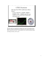
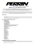
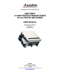
PDXTuning
PDXTuning
PDXTuning
PDXTuning
PDXTuning
PDXTuning
PDXTuning
PDXTuning
PDXTuning
The Quick Guide To Subaru
Tuning with the UTEC
Part Deux
The Ginge’s UTEC tuning experience
As of 2007
PDXTuning
PDXTuning
PDXTuning
PDXTuning
PDXTuning
PDXTuning
PDXTuning
PDXTuning
PDXTuning
Picture is from Subiefest 1, where mick_the_ginge placed 2nd in the time attack. Not
bad for a wagon.
1
PDXTuning
PDXTuning
PDXTuning
PDXTuning
PDXTuning
PDXTuning
PDXTuning
PDXTuning
PDXTuning
Updates
• 09/07/2003 – Initial Version
• 02/26/2004 – Added information on 4.1
firmware release
• 03/14/2007 – Update based on 5.8 firmware
release
• General Clean up
• Includes tuning with the new Speed Density
mode
PDXTuning
PDXTuning
PDXTuning
PDXTuning
PDXTuning
PDXTuning
PDXTuning
PDXTuning
PDXTuning
2
PDXTuning
PDXTuning
PDXTuning
PDXTuning
PDXTuning
PDXTuning
PDXTuning
PDXTuning
PDXTuning
PDXTuning
PDXTuning
Agenda
• UTEC Overview
• UTEC and knock
• Map Tuning
• Fuel – 0% tuning and Open Loop Fueling
• Fuel tuning with Speed Density mode
• Timing, Boost, Parameters
• Logging
• Third party UTEC GUI
• Spare Solenoid Usage
PDXTuning
PDXTuning
PDXTuning
PDXTuning
PDXTuning
PDXTuning
PDXTuning
3
PDXTuning
PDXTuning
PDXTuning
PDXTuning
PDXTuning
PDXTuning
PDXTuning
PDXTuning
PDXTuning
The UTEC
User Tunable Engine Computer
The UTEC is not a piggyback! Past crossover it
has 100% control of fuel, timing and boost
Override control of:
Fueling
Timing
Boost
PDXTuning
PDXTuning
PDXTuning
PDXTuning
PDXTuning
PDXTuning
PDXTuning
PDXTuning
PDXTuning
4
PDXTuning
PDXTuning
PDXTuning
PDXTuning
PDXTuning
PDXTuning
PDXTuning
PDXTuning
PDXTuning
Expectations
• What you are going to learn
The basics required to tune with the UTEC
• What you are NOT going to learn
• Real WRX/STi tuning!
• Caution: This will be enough information to destroy
your WRX!
• ** READ THE UTEC USER MANUAL **
• This quick guide does not replace it
PDXTuning
PDXTuning
PDXTuning
PDXTuning
PDXTuning
PDXTuning
PDXTuning
PDXTuning
PDXTuning
5
PDXTuning
PDXTuning
PDXTuning
PDXTuning
PDXTuning
PDXTuning
PDXTuning
PDXTuning
PDXTuning
Just in case you did not read the last bullet on the previous page
PDXTuning
PDXTuning
PDXTuning
PDXTuning
PDXTuning
PDXTuning
PDXTuning
PDXTuning
PDXTuning
6
PDXTuning
PDXTuning
PDXTuning
PDXTuning
PDXTuning
PDXTuning
PDXTuning
PDXTuning
PDXTuning
UTEC Overview
• How does the UTEC enable more Horse
Power?
• It doesn’t! BOOST = POWER, TIMING =
POWER, FUEL = POWER, the UTEC just
enables you to correctly tune for boost and
aftermarket parts
PDXTuning
PDXTuning
PDXTuning
PDXTuning
PDXTuning
PDXTuning
PDXTuning
PDXTuning
PDXTuning
All EM’s enable you to modify fuel, timing, boost, some do it better than others.
High flow exhausts yielding better VE, boost and correct timing enables your EJ
block to generate more power. The EM enables you to correctly setup the fueling
and timing to match your new parts.
7
PDXTuning
PDXTuning
PDXTuning
PDXTuning
PDXTuning
PDXTuning
PDXTuning
PDXTuning
PDXTuning
UTEC and Knock
• UTEC only corrects knock when it
is in control of timing:
• TPS > Crossover Or when
Speed Density Crossover has
been met
• Timing retarded by default 2
degrees for 100 crank cycles
• Continues to retard timing
until knock is no longer detected
Knock/Detonation is the
spontaneous combustion
of the end-gas
(remaining fuel/air
mixture) in the chamber.
This occurs after the
spark.
• Default setting are very sensitive
• Which is a good thing unless
you have a noisy built block
PDXTuning
PDXTuning
PDXTuning
PDXTuning
PDXTuning
PDXTuning
PDXTuning
PDXTuning
PDXTuning
Interestingly the UTEC will still flash the CEL when it’s not in control of timing.
It’s just a flashing of the CEL, as the UTEC is not in control of timing no
adjustments are made.
8
PDXTuning
PDXTuning
PDXTuning
PDXTuning
PDXTuning
PDXTuning
PDXTuning
PDXTuning
PDXTuning
New Knock Settings
• Found Under Parameters -> Knock Constants
• Automated knock timing retard is NEW
• This is the amount of timing that is automatically
taken off the whole timing map after knock is
detected.
• Automatic retard values are lost once the car is
switched off
New
PDXTuning
PDXTuning
PDXTuning
PDXTuning
PDXTuning
PDXTuning
PDXTuning
PDXTuning
PDXTuning
9
PDXTuning
PDXTuning
PDXTuning
PDXTuning
PDXTuning
PDXTuning
PDXTuning
PDXTuning
PDXTuning
New Knock Settings Continued
• Remember if you are getting knock over
and over again, TUNE your map
• Max Retard IMO is a little too big (5), if the
UTEC has to take out that much timing
you’re in big trouble -> Set it at 3
• Raise the window to 10, this is the time
between auto corrections
3
PDXTuning
PDXTuning
PDXTuning
PDXTuning
PDXTuning
PDXTuning
PDXTuning
10
PDXTuning
PDXTuning
10
PDXTuning
PDXTuning
PDXTuning
PDXTuning
PDXTuning
PDXTuning
PDXTuning
PDXTuning
PDXTuning
PDXTuning
PDXTuning
PDXTuning
Map Tuning
Fuel
Timing
Boost
Parameters
PDXTuning
PDXTuning
PDXTuning
PDXTuning
PDXTuning
PDXTuning
11
PDXTuning
PDXTuning
PDXTuning
PDXTuning
PDXTuning
PDXTuning
PDXTuning
PDXTuning
PDXTuning
Choose the fueling mode
• The UTEC supports 3 modes of fueling
• Classic MAF offset (Don’t use this mode)
• Fueling based on MAF offset – Fools ECU to
adding/subtracting fuel at give load
• Open Loop Fueling (OLF) (Default mode)
• UTEC generated MAF based fueling. Past crossover
UTEC has 100% control of injector duty cycle based
on MAF/MAP/RPM voltage
• Speed Density (Way cool)
• Fueling based on volumetric efficiency of engine,
past crossover UTEC has 100% control of injector
duty cycle based on MAP/RPM
PDXTuning
PDXTuning
PDXTuning
PDXTuning
PDXTuning
PDXTuning
PDXTuning
PDXTuning
PDXTuning
I would not use Classic fueling mode anymore. Either pick open loop fueling or
speed density mode.
12
PDXTuning
PDXTuning
PDXTuning
PDXTuning
PDXTuning
PDXTuning
PDXTuning
PDXTuning
PDXTuning
Fuel Tuning
Information applicable to classic MAF
modification in 3.1 and 4.1 mode, Open Loop
Fueling and Speed Density mode
PDXTuning
PDXTuning
PDXTuning
PDXTuning
PDXTuning
PDXTuning
PDXTuning
PDXTuning
PDXTuning
13
PDXTuning
PDXTuning
PDXTuning
PDXTuning
PDXTuning
PDXTuning
PDXTuning
PDXTuning
PDXTuning
MAP Load Point (MLP)
• The UTEC only uses TPS while below the
programmed crossover (except for the boost
map which is TPS based)
• Greater than crossover and the map load is
based on boost (MAP)
In this example TPS crossover is set to 35%
Past crossover the MLP can be viewed in UTEC logger #1
Remember MLP is based on actual boost pressure - MAP
PDXTuning
PDXTuning
PDXTuning
PDXTuning
PDXTuning
PDXTuning
PDXTuning
PDXTuning
PDXTuning
14
PDXTuning
PDXTuning
PDXTuning
PDXTuning
PDXTuning
PDXTuning
PDXTuning
PDXTuning
PDXTuning
Know your MAP based load points
• Settings found in
SPECIAL
CONSTANTS menu
• Defined as
• Min PSI (0 default)
• Max PSI (18 default)
Load
Column
Min PSI
Default
Max PSI
Default
10%
0.0
2.0
20%
2.0
4.0
30%
4.0
6.0
40%
6.0
8.0
50%
8.0
10.0
60%
10.0
12.0
70%
12.0
14.0
80%
14.0
16.0
90%
16.0
18.0
100%
18.0
18+
*Modify Max PSI setting to your desired PSI*
PDXTuning
PDXTuning
PDXTuning
PDXTuning
PDXTuning
PDXTuning
PDXTuning
PDXTuning
PDXTuning
Simple, know you load points. When logging you will see loads of data, the most
important of these are the rpm and Map Load Point, MLP for short. The MLP is
based off the Manifold Absolute Pressure, MAP. The MLP is a range from 0-100%.
The above chart shows how the MLP corresponds to MAP if the UTEC defaults are
used. For most cars the defaults can be used.
The load point or load zone as it is sometimes called is very important data for
tuning. When analyzing UTEC log files look at the RPM values and the load point
to work out which cell was in use.
In the logger files you will sometimes see that the MAP lags behind the MLP. Trust
the MLP, it reflects what cell the UTEC is actually using at that time. The logger
MAP values are averaged to ease analysis. Tune using the RPM and MLP…. The
UTEC always uses absolute pressure even if the logger is set to gauge.
15
PDXTuning
PDXTuning
PDXTuning
PDXTuning
PDXTuning
PDXTuning
PDXTuning
PDXTuning
PDXTuning
Setting the MAX MAP
• MAX Mapping must be set BEFORE you
continue to tune.
• Caution: Stock MAP sensor only reads up to ~23.3 psi
• DO NOT SET MAX MAP Higher than this while using the
stock MAP sensor
Stage Setup Guidelines
Stock WRX / Stage 2
Stage 4 WRX
Stock STi / Stage 2
Stage 4 STi (Green/Red/GT Turbo)
Stage 4 STi with aftermarket MAP
PDXTuning
PDXTuning
PDXTuning
PDXTuning
PDXTuning
PDXTuning
MAP MAX PSI
18
20
18
22
30
PDXTuning
PDXTuning
PDXTuning
For information on installing an aftermarket MAP sensor I suggest you search
NASIOC as there are a couple of good threads on the subject. I installed the
TurboXS MAP sensor in pace of my stock sensor and the recalibrated my ECU to
work with the new sensor. Caution: The ECU uses MAP for starting and the first 30
seconds. If you do install an aftermarket MAP sensor in place of the stock one you
will need to very carefully calibrate the stock ECU. Get the calibration wrong and
your car will not start. The STI is especially sensitive to the MAP settings.
16
PDXTuning
PDXTuning
PDXTuning
PDXTuning
PDXTuning
PDXTuning
PDXTuning
PDXTuning
PDXTuning
Caution When Fuel Tuning
• Stock O2 sensor is
Narrow-wideband but it’s
not recommended to tune
against it under WOT
• Do not use the WOT AFR
reading to tune!
• Even when UTEC log reads
rich, AFR maybe as high as
12.5:1 (Far too lean without
water injection)
• Lean AFR’s lead to high
If in doubt go RICH
(But not too rich as that will cause misfire)
PDXTuning
PDXTuning
PDXTuning
PDXTuning
EGT’s and possible
engine damage
• Tune fuel using a real
wideband O2 sensor
PDXTuning
PDXTuning
PDXTuning
PDXTuning
PDXTuning
The stock WRX front O2 sensor is wideband but you must not tune against the AFR
you read from it. It’s only wideband to enable the ECU is to run in closed loop fuel
tuning mode. This is where the ECU monitors the front O2 sensor and try’s to keep
the AFR’s at as close to 14.9:1 AFR as possible. The ECU is only in this mode
under certain easy driving conditions and the sensor works great within those
regions.
Outside of these regions the wideband is ignored by the ECU and it runs on open
loop mode. Using delta dash I can see that the sensor pegs at about 11.5:1, the
UTEC logs read rich under about 12.5:1. I do not trust the stock sensor and highly
recommend an aftermarket wideband O2 setup. Loads of good ones around like the
TurboXS Tuna and the LM1’s. I have a TurboXS Tuna. I must admit I like the Tuna
as the wideband value is displayed right in with the UTEC logs.
Anyway, buy or borrow a wideband to enable you to tune your fuel correctly.
17
PDXTuning
PDXTuning
PDXTuning
PDXTuning
PDXTuning
PDXTuning
PDXTuning
PDXTuning
PDXTuning
Tuning the 0% column for NONstock injectors
0% column applies
to all RPM’s below
TPS crossover
• If you have larger than stock injectors
you should tune your 0% column
using an OBDII Scanner
• Effects ECU’s Long Term and Short
Term trim values
• Typical Stage4 map yields LT values
from +20 to –20%
• Fine to be within –7% to +7% (I think
that -7% to 0 is better)
• This is not required if you’re still
using the stock injectors
• Add/remove a percentage of MAF to
get the trims in line.
PDXTuning
PDXTuning
PDXTuning
PDXTuning
PDXTuning
PDXTuning
PDXTuning
PDXTuning
PDXTuning
If you are running larger than stock injectors you will have to tune your 0% fuel
column. Your goal is to get the ECU’s short and long term fuel trim values as close
to 0 as possible. The UTEC cannot read the ECU fuel trims, an ODBII scanner or
other logging device such as delta dash can be used to capture the fuel trim values.
The ECU can only correct +-25% fueling to compensate for injectors. If you install
STi injectors without engine management you will see that the ECU will max out
both ST and LT trims at –25. The ECU is trying to remove loads of fuel to
compensate for the larger injectors.
The UTEC 0% column is used to fool the ECU into thinking that less air is going
into the engine thus the injectors do not need to be fired so much.
Getting the ST and LT trims under control will lead to a more stable idle and better
overall fuel tune.
In 3.1 fueling mode getting the ST and LT trims under control is very important.
18
PDXTuning
PDXTuning
PDXTuning
PDXTuning
PDXTuning
PDXTuning
PDXTuning
PDXTuning
PDXTuning
Tuning the 0% column for NONstock injectors – OLF / SD Mode
0% column applies
to all RPM’s below
TPS crossover
• When using open loop fueling or SD
•
•
•
•
PDXTuning
PDXTuning
PDXTuning
mode the UTEC automatically does
0% fueling compensation.
The value used is calculated from the
difference between the Stock injector
size and the UTEC injector size
The larger the difference the more
modification is done.
Follow the attached notes to work out
how to really do it.
In SD mode the injector latency also
effects the 0%
PDXTuning
PDXTuning
PDXTuning
PDXTuning
PDXTuning
PDXTuning
Stock intake or normal sized aftermarket. Say the UTEC stock injector size is set to 400 and the
UTEC size is set to 500. This means the UTEC injector size is larger than stock thus the UTEC will
remove fuel from the 0%. The larger the difference the more fuel the UTEC will want to remove. It’s
actually doing an automatic MAF modification for you.
If you have a reflashed ECU for your setup the stock size should match the UTEC size. The UTEC
size will be the actual size of your injectors.
I think in the future the UTEC will directly calculate the injector duty cycle even in the 0% rather
than doing the modification as a MAF offset.
BigMAF setups. If you have a BigMAF then it’s a little more complex to work out the values. A
bigMAF will flow more air so you cannot use the actual injector size as the UTEC injector size. With
a BigMAF it will always be smaller than what you have installed. Remember the UTEC does not
know you have a BigMAF and it will fuel based on a stock intake. For example if you have an Sti
with Perrin 816 injectors and a BigMaf then I find that setting the UTEC injector size to 650 gets you
close. Leave the stock size at 550. If you look at the fuel trims and they are either too positive or too
negative change the stock injector size. Have the stock size closer to the UTEC size will mean less
fuel is removed. Do this if the trims are positive. More difference will force the UTEC to remove
more fuel, do this if the trims are negative.
19
PDXTuning
PDXTuning
PDXTuning
PDXTuning
PDXTuning
PDXTuning
PDXTuning
PDXTuning
PDXTuning
Tuning the 0% column – Simple
Tuning Procedure #1
• Warm the car up
• Reset the ECU
• While in neutral
• Rev car from idle to 5000+ RPM while logging
LT and ST
• Adjust 0% to add/remove fuel where needed
– If LT and ST show positive, ADD fuel
– If LT and ST show negative, REMOVE fuel
• Reset ECU and Repeat
• Do this until LT and ST read close to 0
PDXTuning
PDXTuning
PDXTuning
PDXTuning
PDXTuning
PDXTuning
PDXTuning
PDXTuning
PDXTuning
Follow these simple notes to tune your 0% UTEC MLP.
20
PDXTuning
PDXTuning
PDXTuning
PDXTuning
PDXTuning
PDXTuning
PDXTuning
PDXTuning
PDXTuning
Tuning the 0% column – Simple
Tuning Procedure #2
• Go drive the car while logging LT and ST
• Under load fuel conditions are different
• Again adjust 0% column to try and get LT
and ST as close to 0 as possible
• It’s never going to be perfect, but it should be
close
TIP: At Idle force ECU to be
removing fuel. Idle seems to
run smoother
PDXTuning
PDXTuning
PDXTuning
PDXTuning
PDXTuning
PDXTuning
PDXTuning
PDXTuning
PDXTuning
Forcing the ECU to take the LT negative at idle does seem to give you a very stable
idle but don’t go too far. The transition to your idle 0% setting leads to a rich spot as
the ecu transitions into that load zone. Too rich at this point and your car will stall.
21
PDXTuning
PDXTuning
PDXTuning
PDXTuning
PDXTuning
PDXTuning
PDXTuning
PDXTuning
PDXTuning
Delta Dash Log of 0% Tune
Very stable idle
Nice and stable LT
ST not too bad
Effect of free air BOV
Short Term
Long Term
PDXTuning
PDXTuning
PDXTuning
PDXTuning
PDXTuning
PDXTuning
PDXTuning
PDXTuning
PDXTuning
This is a Delta Dash log from a quick run. Notice the ST trim jumps around loads.
This is normal as the ECU is on closed loop fuel control and uses ST to make quick
fuel adjustments. If a ST pattern is spotted by the ECU it uses the more coarse LT
trim value to apply a more permanent adjustment. This is called fuel learning and
the ECU is very good at it. It’s typical to see steps in the LT trim values.
Notice the ST spike, that’s the BOV venting producing a rich condition. The ECU is
back in closed loop fuel tuning mode and immediately tries to correct the condition,
thus the negative spike on the ST trim.
22
PDXTuning
PDXTuning
PDXTuning
PDXTuning
PDXTuning
PDXTuning
PDXTuning
PDXTuning
PDXTuning
Knock after shift (fuel correction)
Add some fuel in
these areas to
minimize knock
after shift
• Knock after shift is usually down to
two things
• #1 Lean conditions just after shift
• #2 Large jump in timing just after shift
• See knock after shift timing correction
• Adding fuel at 5000+ RPM’s in the
lower boost range can minimize this
effect
• Having timing values down in the
lower columns also helps
PDXTuning
PDXTuning
PDXTuning
PDXTuning
PDXTuning
PDXTuning
PDXTuning
PDXTuning
PDXTuning
While we are on the subject of the 0% column I should also mention something that
is being called shift knock. Shift knock is knock that is detected between shifts. This
type of knock is down to a couple of conditions. The first is the lean condition that
happens as you shift the second is the timing that the ECU runs during the shift.
Both the lean condition and the high timing advance lead to knock.
These two effects happen when the UTEC gives back control to the ECU. Both
knock conditions can be fixed by locking down fueling and timing in the 0%
column.
To reduce the chance of shift knock add some extra fuel in the 0% column from
around 5000 rpm and up. Don’t worry about the fuel trim values, the ECU is in
open loop mode at 5000 rpm so the extra fuel will not effect them. This extra fuel
reduces the lean condition thus reducing the risk of shift knock.
Watch out, if you add too much fuel in this area you could end up with some meaty
backfire due to un-burnt fuel in the exhaust. This will damage cats and could also be
miss sensed as knock. Also if you happen to do a low load run up to these high
rpm’s this extra fuel could cause misfires.
23
PDXTuning
PDXTuning
PDXTuning
PDXTuning
PDXTuning
PDXTuning
PDXTuning
PDXTuning
PDXTuning
PDXTuning
PDXTuning
Fuel Tuning
OPEN LOOP FUELING Mode
PDXTuning
PDXTuning
PDXTuning
PDXTuning
PDXTuning
PDXTuning
PDXTuning
More on fuel tuning
24
PDXTuning
PDXTuning
PDXTuning
PDXTuning
PDXTuning
PDXTuning
PDXTuning
PDXTuning
PDXTuning
Why Open Loop Fueling
• Eliminates the delay in transitioning from
closed to open loop fuel control in the stock
ECU.
• Big issue with the 2004+ WRX ECU.
• Enables Programmable Rev limit
• Enables injector scaling
• Eases fuel tuning when larger than stock
injectors are installed
• Do not use scaling with a classic style fuel map.
PDXTuning
PDXTuning
PDXTuning
PDXTuning
PDXTuning
PDXTuning
PDXTuning
PDXTuning
PDXTuning
The #1 reason the UTEC need to do full fuel control is due to the 2004 WRX closed
to open loop transition delay. Basically what was happening was that the ECU was
programmed with a delay between closed loop fueling and open loop fueling. In
closed loop ECU fueling it tries to target 14.9:1 reading the front O2 sensor. The
delay was going into open loop mode where the ECU just has a fuel background
map. This delay caused the car to run really lean going onto boost. Knock,
knock…….
Anyway with the UTEC Open Loop Fueling this issues goes away as the UTEC is
creating the background fuel map. This is very cool as it’s MAF based. As soon as
you go over the TPS crossover point which the default for OLF is 25% the UTEC is
in control. Hence the delay is not an issue as the ECU is now doing nothing.
2 other features are the controllable rev limit and the injector scaling. Injector
scaling will help those with larger than stock injectors. If you are using STi injectors
don’t use the scaling. Lets face it there are many maps available for these injectors
already. Stick with the default scaling and use a standard map. You can still use
OLF without injector scaling. Also don’t expect to be able to install 740’s and just
set the scaling. It requires more work than that.
DO NOT USE INJECTOR SCALING WITH A CLASSIC STYLE MAP>>>>>
25
PDXTuning
PDXTuning
PDXTuning
PDXTuning
PDXTuning
PDXTuning
PDXTuning
PDXTuning
PDXTuning
What is Open Loop Fueling?
UTEC MAF BASED FUELING
Full fuel control UTEC is 100% in control of fueling past
crossover
CONSITENT FUELING, no more long term trim offset
MAF base fueling
UTEC calculates injector duty
cycle based on MAF/RPM
a
UTEC is in full control of
fueling
PDXTuning
PDXTuning
PDXTuning
PDXTuning
PDXTuning
PDXTuning
PDXTuning
PDXTuning
PDXTuning
Open loop fueling is just a name for the UTEC being in full control of the injectors.
Previously the UTEC fueling was an offset of the ECU fueling. The issues with this
was if the ECU changed it fueling the UTEC fueling got screwed up. This could
happen if the long term trim value changed over time.
With OLF the UTEC when in control creates the background map to replace
everything that the ECU is doing in respect to fuel. To do this the UTEC reads the
MAF signal to calculate the injector duty cycle. Very cool and it takes the UTEC
one step closer to being a standalone ECU.
26
PDXTuning
PDXTuning
PDXTuning
PDXTuning
PDXTuning
PDXTuning
PDXTuning
PDXTuning
PDXTuning
Turning on Open Loop Fueling
• Requires 4.1 or above firmware
• To enable:
• Enter the Open Loop Fueling menu option
• Turn on Open Loop Fueling. Change to be 1
– On by default in 4.2c and above
– New base maps from TurboXS are tuned for OLF
Screen parameters may have changed a little since this screen shot was taken
PDXTuning
PDXTuning
PDXTuning
PDXTuning
PDXTuning
PDXTuning
PDXTuning
PDXTuning
PDXTuning
Enabling OLF is easy. GO into the OLF menu option of the 4.1 or above firmware
and turn OLF to 1.
Even if you have STi injectors DO NOT MODIFY THE INJECTOR FLOW.
DO NOT MODIFY THE INJECTOR FLOW (scaling) - DO NOT MODIFY THE
INJECTOR FLOW - DO NOT MODIFY THE INJECTOR FLOW
With OLF enabled I suggest you re-check your AFR’s with a wideband. The OLF
background fuel map is close to what the ECU does but not exactly what it does. I
noticed that I actually ran leaner at lower load zones and much richer at the top end.
But the differences were within acceptable ranges so I stuck with my original map.
STI Injectors and larger.
The reason that you do not change the Injector flow scaling value is that the map
you are running was designed to compensate for stock ECU fueling with larger
injectors installed. If you change the flow scale are run a map that has negative
values you are going to run super lean..
27
PDXTuning
PDXTuning
PDXTuning
PDXTuning
PDXTuning
PDXTuning
PDXTuning
PDXTuning
PDXTuning
Changing Injector Flow Scaling
• Requires 4.1 or above firmware
• To enable:
• Enter the OLF menu option
• Modify Injector Flow:
– Supports 300 to 1000 flow rate
UTEC generates
AFR curve
based on
MAF/RPM and
scaling factor
Actual Size of
injectors installed
Size the ECU thinks
the injectors are
PDXTuning
PDXTuning
PDXTuning
PDXTuning
PDXTuning
PDXTuning
PDXTuning
PDXTuning
PDXTuning
If you have a larger than stock intake you will have to be very careful with the value
you enter. Too large and your car is going to run lean even with the map zero. Start
low and work up.
Don’t touch the stock injector size if you have not re-flashed your ECU.
28
PDXTuning
PDXTuning
PDXTuning
PDXTuning
PDXTuning
PDXTuning
PDXTuning
PDXTuning
PDXTuning
Modified Stock Injector Flow
Scaling
• Start with a low value
• The injectors may flow 816cc but do they
match your MAF readings
• You maybe flowing more air! BigMAF for example
• Start with injector flow set at 740 (guess and
what I usually use)
• Increase this value while monitoring AFR curve
with wideband O2 sensor
• Fine tune AFR curve using a map overlay
PDXTuning
PDXTuning
PDXTuning
PDXTuning
PDXTuning
PDXTuning
PDXTuning
PDXTuning
PDXTuning
Just a reminder that you cannot just enter a flow value and expect everything to
work as expected. Modified stock injectors are a great thing for those who need
more fuel but even with the UTEC injector scaling you are going to have to fine
tune you fuel map.
29
PDXTuning
PDXTuning
PDXTuning
PDXTuning
PDXTuning
PDXTuning
PDXTuning
PDXTuning
PDXTuning
Fuel Map Tuning
0% column applies
to all RPM’s below
TPS cross over point
PDXTuning
PDXTuning
PDXTuning
Past cross over point, Throttle > 25%,
load is represented by Mass Absolute
Pressure, MAP as defined in the
SPECIAL CONSTANTS
PDXTuning
PDXTuning
PDXTuning
PDXTuning
PDXTuning
PDXTuning
Just a recap. Under the TPS crossover point the 0% fueling values are used. Over
the crossover point the 10-100% load columns are used and the load reference
swaps to MAP.
30
PDXTuning
PDXTuning
PDXTuning
PDXTuning
PDXTuning
PDXTuning
PDXTuning
PDXTuning
PDXTuning
Fuel Tuning Table
• More positive numbers represent more fuel
• A value of 2 is more fuel than an value of 1
• A value of –6 is less fuel than a value of –5
• Get the drift………
You are modifying the Mass
Air Flow, MAF, voltage reading
by a percentage
Applies to both classic
and open loop fueling modes
PDXTuning
PDXTuning
PDXTuning
PDXTuning
PDXTuning
PDXTuning
PDXTuning
PDXTuning
PDXTuning
The values that you type into the fuel map do NOT represent injector duty cycle
they represent a MAF offset percentage. This is the same in both fueling modes
whether the ECU is controlling the background fuel map or if the UTEC is running
in open loop fueling mode and is controlling the background map.
A more positive number represents more fuel, a more negative number represents
less fuel.
31
PDXTuning
PDXTuning
PDXTuning
PDXTuning
PDXTuning
PDXTuning
PDXTuning
PDXTuning
PDXTuning
Fuel Tuning >TPS crossover
Fueling for Rapid Spool Up
Always use a Wideband O2 sensor to tune your fuel values!
Over TPS crossover - UTEC load swaps to MAP
Keep Low RPM and Low Boost
Fuel values on the leaner side
This creates HOTTER EGT’s
which helps the turbo spool
quicker
Richen up fuel at mid RPM and
mid boost (Safer for your WRX if
you don’t have water injection)
My AFR target was 12.5:1 up until 2750 RPM
PDXTuning
PDXTuning
PDXTuning
PDXTuning
PDXTuning
PDXTuning
PDXTuning
PDXTuning
PDXTuning
Far too often I see threads about slow spool up on the WRX turbo or after market
turbo’s with the UTEC. With after market turbo’s some of this is because the things
are huge and do have a slow spool up. Some of it is due to the car running really
rich in the spool up zones.
The UTEC base maps are good but they can be a little rich. This is great and
conservative but can lead to slow turbo spool up as the EGT’s don’t get very hot.
If you have this issue you should use a wideband O2 sensor and see if you are
running rich in the spool up area. 10.5:1 maybe perfect at full boost but 12.5:1 AFR
will create hotter EGT’s and aid spool up. Do not lean this area out too much as you
will end up losing power.
32
PDXTuning
PDXTuning
PDXTuning
PDXTuning
PDXTuning
PDXTuning
PDXTuning
PDXTuning
PDXTuning
What the MAF offsets actually does
Modified
Measured
RPM MAP MAF TPS Site Count Ign#1 Inj#1 Ign Fuel Boost MAF AFR
5042 +21.9 4.4 100 90
00 +17.0 68.1 +17.2 -4.8 ECU. 4.1 11.76
• In this example the actual measured MAF voltage
is 4.4volts
• The map applies a -4.8% modification resulting in a
modified MAF voltage of 4.1 volts
• The Open Loop Fueling uses the modified MAF
voltage value as the source of it’s fuel lookup.
• The UTEC has a pre-programmed background map
that you cannot access.
PDXTuning
PDXTuning
PDXTuning
PDXTuning
PDXTuning
PDXTuning
PDXTuning
PDXTuning
PDXTuning
33
PDXTuning
PDXTuning
PDXTuning
PDXTuning
PDXTuning
PDXTuning
PDXTuning
PDXTuning
PDXTuning
Fueling Part 2
Always use a Wideband O2 sensor to tune your fuel values!
AFR data is coming
from Wideband
Not shown.
Much easier with a TXS “Tuna”,
AFR data right in the log file
Or use UTI – See additional
tuning tools at the end
Log to correlate AFR/RPM/MAP
data back to UTEC load column
reference
Adjust column to meet target AFR
My AFR target was 11.5:1
PDXTuning
PDXTuning
PDXTuning
PDXTuning
PDXTuning
PDXTuning
PDXTuning
PDXTuning
PDXTuning
Funny after all those slides this is the most important. Here you can see a snippet
from a UTEC log 1. I was not using the Tuna for this run so you cannot see the AFR
data. AFR data was in a separate log from my Tech Edge wideband. To tune you
should reference the rpm and the map load points. The MLP’s are highlighted in the
above slide.
From the RPM and MLP work out which load cell to modify to either add or
subtract fuel at that point. I try are target 12:5:1 up to 2750, then come down to
11.5:1 up to 5000 and finally down to 11:1 at redline. Remember to add fuel make
the value more positive and to subtract fuel make the value more negative. If you
have water injection you should be able to run leaner at the top end. 12:1… sweet.
While you are fuel tuning check the injector duty cycle. If it’s already at 100% and
you are running too lean then you will have to turn the boost down at that point.
Once the injectors hit 100% you cannot add anymore fuel.
Notice that you do not enter all of the load zones. You kind of go into ranges of
them. This is typical as unless you have access to a load set dyno it’s hard to tune all
load zones. For ranges above a zone that are not entered I always go richer and for
ranges below a zone that are not entered I always go leaner. Not much either way.
Daily driving I enter these other load zones and always check that I’m running more
on the rich side than the lean side.
34
PDXTuning
PDXTuning
PDXTuning
PDXTuning
PDXTuning
PDXTuning
PDXTuning
PDXTuning
PDXTuning
Knock correction and Fuel
Tuning
• Add fuel to correct knock conditions
• WRX typical problem areas
• Around 4000 RPM (peak boost)
• Around 5500-5750 RPM (knock happy area)
• Stage4 Map example
• Rich around 4000 RPM
Caution: Too
much fuel
will lead to
misfire
PDXTuning
PDXTuning
PDXTuning
PDXTuning
PDXTuning
PDXTuning
PDXTuning
PDXTuning
PDXTuning
The WRX has a couple of points that seem to be more prone to knock than others,
around 4000 and 5500 rpm’s. This I am sure is down to engine design. The knock
issues can be reduced by adding a little extra fuel in these areas. You can see these
area’s in the timing map as well. Just look at the lower timing values at these points.
Do not add too much fuel, just a tad. The hesitation that some people feel with their
cars is typically down to running too rich in an area. Just a little extra fuel to help
reduce knock conditions.
35
PDXTuning
PDXTuning
PDXTuning
PDXTuning
PDXTuning
PDXTuning
PDXTuning
PDXTuning
PDXTuning
Programmable Rev Limit
• Now UTEC controls fueling, it can also control
rev limit – Way cool ☺
• Warning: Unless you have strengthened internals
changing rev limit could cause serious engine
damage
STi Default is
low IMO. Set if
to 72 for a block
with stock
internals
PDXTuning
PDXTuning
PDXTuning
PDXTuning
PDXTuning
PDXTuning
PDXTuning
PDXTuning
PDXTuning
Final note on the programmable rev limit. For those who want to run a little past the
ECU set rev limit at 7200 you can with this new feature. Don’t get stupid with this
setting. The stock internals were not made to run at 9000 rpm so don’t go their.
I like to shift at 7000 rpm and noticed that with the 200 rpm offset of the tachometer
I would hit rev limit during a hard shift. My solution was to up the rev limit to 7500.
Very sweet shifts now with the launch control set at 6000 perfect for flat foot
shifting.
36
PDXTuning
PDXTuning
PDXTuning
PDXTuning
PDXTuning
PDXTuning
PDXTuning
PDXTuning
PDXTuning
PDXTuning
PDXTuning
Fuel Tuning
Speed Density Mode
PDXTuning
PDXTuning
PDXTuning
PDXTuning
PDXTuning
PDXTuning
PDXTuning
37
PDXTuning
PDXTuning
PDXTuning
PDXTuning
PDXTuning
PDXTuning
PDXTuning
PDXTuning
PDXTuning
Speed Density Parameter Setup
• In Speed Density (SD) mode the MAF sensor is
only used BELOW crossover
• After crossover fueling is calculated using a based
volumetric efficiency table
• Load points are RPM/MAP based after crossover
• Base table can be offset using values in fuel table
• MAF sensor is still required even in SD mode
• To Enable SD mode
• OLF = 1 (on)
• Fuel Mode = (SD mode on (MAF mode off))
• Sorry I did not bother to capture a screen shot of the Fuel
Mode on
• Don’t forget to set the engine CC, 2L or 2.5L
• 2000, 2500
PDXTuning
PDXTuning
PDXTuning
PDXTuning
PDXTuning
PDXTuning
PDXTuning
PDXTuning
PDXTuning
38
PDXTuning
PDXTuning
PDXTuning
PDXTuning
PDXTuning
PDXTuning
PDXTuning
PDXTuning
PDXTuning
Speed Density Setup Continued
• Set UTEC injector size to ACTUAL size of
injectors
• Examples:
• WRX with modified stock “blues”
– Set Injector flow to ~800
• STi with modified stock injectors
– Set injector flow to ~800
• If stock sized intake then set stock injectors to the
size the ECU think are installed
Actual injector size
PDXTuning
PDXTuning
PDXTuning
PDXTuning
PDXTuning
PDXTuning
PDXTuning
PDXTuning
PDXTuning
39
PDXTuning
PDXTuning
PDXTuning
PDXTuning
PDXTuning
PDXTuning
PDXTuning
PDXTuning
PDXTuning
SD and the BigMAF
• Remember the MAF sensor is still used
below UTEC crossover
• Still set the Injector size to the ACTUAL
size of the injector (SD fueling is calculated
from this value)
• Monitor the fuel trims as
previously discussed and
change the stock setting to
bring the trims in line
• Between 650-700 has worked
PDXTuning
PDXTuning
PDXTuning
PDXTuning
PDXTuning
PDXTuning
PDXTuning
PDXTuning
PDXTuning
40
PDXTuning
PDXTuning
PDXTuning
PDXTuning
PDXTuning
PDXTuning
PDXTuning
PDXTuning
PDXTuning
Injector Latency
• The use of the correct injector latency for given
injectors in critical in getting the car to idle
smoothly and the latency can be used to modify
the lower load fueling
• Injector latency is the millisecond value added to
the injector duty
• Added to compensate for the injectors physical
mechanical opening delay
• Example:
• Fuel trims are very minus at idle and light throttle
– Increase the injector latency value a little adds fuel which should
help with the lean condition
• It’s a very small amount so should not offset the higher load
fueling that much
• If fueling is way off use the standard approach, injector
scaling and 0% MAF modification
PDXTuning
PDXTuning
PDXTuning
PDXTuning
PDXTuning
PDXTuning
PDXTuning
PDXTuning
PDXTuning
41
PDXTuning
PDXTuning
PDXTuning
PDXTuning
PDXTuning
PDXTuning
PDXTuning
PDXTuning
PDXTuning
Sample Injector Latency values
• Base information from NASIOC thread
• Additional “real life” tuning information added
A value a little smaller works a little better than the actual latency values specified
PDXTuning
PDXTuning
PDXTuning
PDXTuning
PDXTuning
PDXTuning
PDXTuning
PDXTuning
PDXTuning
42
PDXTuning
PDXTuning
PDXTuning
PDXTuning
PDXTuning
PDXTuning
PDXTuning
PDXTuning
PDXTuning
TPS Crossover
• All crossover parameters have to be true for
UTEC to go into SD mode
• TPS / MAP / RPM settings
TPS is fine at 25% unless
you really want to tune the
10-20% MLP for a smooth
crossover
Setting it to 0 means that as
soon as the other parameters
are met the UTEC enables
SD mode fueling
Leaving TPS at 25% means cruise AFR is
typically under ECU closed loop control,
which is good for fuel efficiency
PDXTuning
PDXTuning
PDXTuning
PDXTuning
PDXTuning
PDXTuning
If set at 0 tuning of the 1020% MLP is very important.
Tune them to 14.7-14.5:1
AFR
PDXTuning
PDXTuning
PDXTuning
43
PDXTuning
PDXTuning
PDXTuning
PDXTuning
PDXTuning
PDXTuning
PDXTuning
PDXTuning
PDXTuning
MAP/RPM Crossover
• MAP crossover is split between two values
• To calculate the actual MAP crossover point
• Take the MAP threshold then add the MAP
hysteresis value to it
• Example
– MAP Threshold = -9 psi
– MAP Hysteresis = 2 psi
• Crossover happens at -7psi (As long as all other
crossover parameters are true)
Default settings work pretty
well
Default RPM setting is fine
PDXTuning
PDXTuning
PDXTuning
PDXTuning
PDXTuning
PDXTuning
PDXTuning
PDXTuning
PDXTuning
44
PDXTuning
PDXTuning
PDXTuning
PDXTuning
PDXTuning
PDXTuning
PDXTuning
PDXTuning
PDXTuning
Speed Density Fuel Tuning
• Spend time tuning the low end of the fuel
map. This will make for a smooth ECU to
UTEC transition
Tune lower load points at as
many rpm points as possible
Volumetric Efficiency (VE).
With 0 in the map this would
read 100
Lean and mean
PDXTuning
PDXTuning
PDXTuning
PDXTuning
PDXTuning
PDXTuning
PDXTuning
PDXTuning
PDXTuning
45
PDXTuning
PDXTuning
PDXTuning
PDXTuning
PDXTuning
PDXTuning
PDXTuning
PDXTuning
PDXTuning
Example SD Fuel Map
With injector size and latency
set correctly the fuel map
typically has to remove lots of
fuel at the lower load points
and RPM to achieve 14:1
Higher loads and RPM
requires less modification
from the UTEC’s base fueling
map to achieve 11:1
Tune map in same way as any
other fuel mode
PDXTuning
PDXTuning
PDXTuning
PDXTuning
PDXTuning
PDXTuning
PDXTuning
PDXTuning
PDXTuning
46
PDXTuning
PDXTuning
PDXTuning
PDXTuning
PDXTuning
PDXTuning
PDXTuning
PDXTuning
PDXTuning
SD Mode and Temperature
• Speed Density is affected by temperature
• Typically only intake temp fueling
compensation is needed
– Coolant correction should be used if you have cold/hot
start problems
Add fuel when it’s
colder than tune
temp
Remove fuel when
it’s hotter than tune
temp
PDXTuning
PDXTuning
PDXTuning
PDXTuning
PDXTuning
PDXTuning
PDXTuning
PDXTuning
PDXTuning
The thing to remember here is that the reference temperature is the temperature at
which you tune the car. Work out what this is by looking at the intake temperature
reported in the UTEC dashboard. In SD mode you will have to add more fuel to the
tune when the intake charge gets colder, the colder the air the more fuel is needed.
As the air gets hotter and lighter then you have to remove fuel to meet your ARF
goal.
The only time you should have to use the ignition compensation is where the intake
charge is very hot. In this case I suggest you remove 2 degrees of timing at the very
hot intake temps.
Coolant corrections are very handy for cars that seem to have cold or hot start
issues. Modded stock injectors are a good example. When the car is very cold the
ECU tends to start the car very rich, sometimes overly rich. Coolant compensation
can be used to lean out the map just while you are warming up the car. Hey presto,
no more black soot on the back of the car.
47
PDXTuning
PDXTuning
PDXTuning
PDXTuning
PDXTuning
PDXTuning
PDXTuning
PDXTuning
PDXTuning
Interesting Log
• This is log pretty interesting and shows the
power of Speed Density Mode
• Can you see why?
• Answer: The MAF sensor is pegged!
• This is not an issue as it’s only used below
crossover.
• That’s one smooth fuel curve
PDXTuning
PDXTuning
PDXTuning
PDXTuning
PDXTuning
PDXTuning
PDXTuning
PDXTuning
PDXTuning
48
PDXTuning
PDXTuning
PDXTuning
PDXTuning
PDXTuning
PDXTuning
PDXTuning
PDXTuning
PDXTuning
PDXTuning
PDXTuning
Timing Tuning
Timing ninja fu
PDXTuning
PDXTuning
PDXTuning
PDXTuning
PDXTuning
PDXTuning
PDXTuning
Time to talk about timing.
49
PDXTuning
PDXTuning
PDXTuning
PDXTuning
PDXTuning
PDXTuning
PDXTuning
PDXTuning
PDXTuning
Timing Map Tuning
0% column applies
to all RPM’s below
TPS cross over point
PDXTuning
PDXTuning
PDXTuning
Past cross over point, Throttle load is
represented by Mass Absolute
Pressure, MAP as defined in the
SPECIAL CONSTANTS
PDXTuning
PDXTuning
PDXTuning
PDXTuning
PDXTuning
PDXTuning
Again a reminder. The 0% column is used when you are blow the TPS crossover.
Once over this point the 10-100% load columns are used and the reference is
swapped to MAP.
50
PDXTuning
PDXTuning
PDXTuning
PDXTuning
PDXTuning
PDXTuning
PDXTuning
PDXTuning
PDXTuning
Timing Advance / Retard
Retard Timing – Less degrees before TDC
Number of Degrees before top dead center
Piston
Advance Timing – More degrees before TDC
Cylinder
Piston
Top Dead Center, TDC
PDXTuning
PDXTuning
PDXTuning
PDXTuning
PDXTuning
PDXTuning
PDXTuning
PDXTuning
PDXTuning
Some basics. Top Dead Center is the upper most point the piston can ever reach.
Timing is measured from this point. Advancing the timing is when you set the spark
to happen before TDC as the piston is on it’s way up. This is measured in degrees.
Retarding the timing is a phrase used to explain reducing the number of degrees
before TDC that the spark happens.
51
PDXTuning
PDXTuning
PDXTuning
PDXTuning
PDXTuning
PDXTuning
PDXTuning
PDXTuning
PDXTuning
Timing Adjustment
• Issue: Default maps don’t have timing down
in the 10-60% columns – Can cause knock
when control passes from ECU to UTEC
and back. Needed for cars with BigMAF
• Resolution: Move timing values into those area
• LEAVE lower RPM 0% under ECU control
Smooth transitions in
timing minimizes the
chance of knock
Try to limit steps in
timing to less than 3
degrees
PDXTuning
PDXTuning
PDXTuning
PDXTuning
PDXTuning
PDXTuning
PDXTuning
PDXTuning
PDXTuning
Some of the issues that are seen with the base maps are that there is no timing
values in the lower load zones. What happens is that as control is passed from the
ECU to the UTEC the timing values can be vastly different. More than 4 degrees
and you can feel it. This jerk sometimes also gets detected as knock.
The solution is to put timing values into the lower load zones.
Another issue that comes up with timing is what I like to call transitional knock.
This is either the above scenario or when the UTEC is in control and timing jumps
up or down more that 2 degrees at a time. In the lower load zones having jumps of
4-8 degrees in timing are fine, but under WOT boost conditions you should avoid
this. Keep the timing steps to 1-2 degrees at a time. This limits the chances to
transitional knock. I have no idea why the car does this, it just does. Smooth
transitions up and down are key to a good feeling car.
What I like about my car is that the power is always coming on and it feels very
smooth. When I go to WOT the boost builds up in a controlled fashion and with
smooth transitions in AFR and timing the car feels smooth. I have no hesitations or
neck snapping jerks. No one has ever said that my car feels slow either.
52
PDXTuning
PDXTuning
PDXTuning
PDXTuning
PDXTuning
PDXTuning
PDXTuning
PDXTuning
PDXTuning
Knock after shift (timing
correction)
Use conservative timing values in upper 0% column to
minimize the chance of knock after shift
ECU runs huge timing advance after high RPM shift.
This can cause knock after shift conditions
PDXTuning
PDXTuning
PDXTuning
PDXTuning
PDXTuning
PDXTuning
PDXTuning
PDXTuning
PDXTuning
Earlier I mentioned that to cure shift knock you can add fuel in the upper 0% load
columns. If you have what you think is shift knock you should also hard code some
of the timing values in the upper load zones as well.
If you look at what the ECU is doing between shifts you can see that sometimes it
wants to run crazy timing values. I have seen up to 41 degrees during a shift. Ripe
knock condition.
From 5250 on my stage4 I put in a timing value of between 18 and 20 degrees. This
seems to reduce the occurrence of shift knock.
Again the only draw back of this is if you run into these columns during your daily
drive rather than during a shift. If you do you will feel the car hesitate as the timing
is locked down. But who redlines their car with less that the crossover TPS.
53
PDXTuning
PDXTuning
PDXTuning
PDXTuning
PDXTuning
PDXTuning
PDXTuning
PDXTuning
PDXTuning
Too much advance!
Too much advance leads to KNOCK and engine destruction!
At redline, too much advance means very high cylinder pressure
BANG – Dead WRX/STi
At a point, more advance does not yield more power
• At that point more advance just takes you closer to knock
• Back timing off 1-2-3 points to create a safe map
• Dyno Proven
PDXTuning
PDXTuning
PDXTuning
PDXTuning
PDXTuning
PDXTuning
PDXTuning
PDXTuning
PDXTuning
As I have said before too much timing advance can mean death to your engine. I
know people who learnt this the hard way!
More boost and fuel is going to give you the big jumps in power, keep timing
conservative. If you are running pump gas definitely keep timing conservative.
One other note to make. If you think your car cannot hold very much timing it
maybe due to your spark plugs. Incorrectly gapped plugs will screw your timing up
so always make sure you have good plugs and they have been gapped correctly. I
use the NGK Iridium plugs: BKR7EIX-11 gapped to 0.028 (good would be between
0.026 and 0.028) I have had no issues with these plugs and this gapping. They don’t
come gapped at this value so make sure you gap them.
54
PDXTuning
PDXTuning
PDXTuning
PDXTuning
PDXTuning
PDXTuning
PDXTuning
PDXTuning
PDXTuning
Timing Low Down
Retarding ignition would increase EGT’s thus help spool up
Negatives: Loss of power because of reduced timing
BETTER: Advance timing at the low RPM’s
More advance means more power
PDXTuning
PDXTuning
PDXTuning
PDXTuning
PDXTuning
PDXTuning
PDXTuning
PDXTuning
PDXTuning
Your car can also hold a stack of timing in the lower load zones. Having timing
advance down here produces that low down power that the WRX can sometime
lack. This is a hard area to tune as you run through the lower load zones very fast
under WOT conditions. I tuned my lower load zones by looking at what the ECU
wanted to run in those areas. Remember at the lower load zones the ECU is seeing
the same boost levels to could in effect be controlling the timing at this point. It’s
not as you have filled in these zones to reduce transitional knock conditions.
55
PDXTuning
PDXTuning
PDXTuning
PDXTuning
PDXTuning
PDXTuning
PDXTuning
PDXTuning
PDXTuning
Timing Values Mid to Top End
Watch for knock in the mid rpm range
Minimal advance here is good ☺
After 3750 or boost peak RPM’s start
ramping timing up
22 – 26 degrees of advance should be
safe at redline
Smooth Transitions, steps of 1-3 are best
Watch for KNOCK !
If you get knock, back off the timing 1-23 degrees at LEAST
PDXTuning
PDXTuning
PDXTuning
PDXTuning
PDXTuning
PDXTuning
PDXTuning
PDXTuning
PDXTuning
Here are just some pointers on timing values in your maps. I do not see many
differences between timing maps of a stage 1 to a stage 4 car. Yes there are some,
just if you are running pump gas the timing seems to be very close match between
stages.
Minimal timing is used as boost comes on. If you have your boost controller set to
have the boost hit hard then you will only be able to run very low timing numbers as
it hits. Some of this could be due to over boost.
At redline I run 24 degrees, I used to run 26 but I think I was past minimum best
timing as I did not gain anymore power.
Remember if you get knock and your AFR’s on on target then back off timing 1,2
or 3 degrees. You are no going to lose power.
56
PDXTuning
PDXTuning
PDXTuning
PDXTuning
PDXTuning
PDXTuning
PDXTuning
PDXTuning
PDXTuning
UTEC Boost Controller Setup
PDXTuning
PDXTuning
PDXTuning
PDXTuning
PDXTuning
PDXTuning
PDXTuning
PDXTuning
PDXTuning
Moving on, nothing to see here……
57
PDXTuning
PDXTuning
PDXTuning
PDXTuning
PDXTuning
PDXTuning
PDXTuning
PDXTuning
PDXTuning
PDXTuning
PDXTuning
Boost Map Tuning
Boost Control is
TPS/RPM based
TPS
RPM
PDXTuning
PDXTuning
PDXTuning
PDXTuning
PDXTuning
PDXTuning
PDXTuning
The UTEC boost controller map is different to the fuel and timing maps as it is
100% RPM/TPS based. At any RPM/TPS point the UTEC can be in control of the
boost.
As people always ask this, yes you can use an external boost controller with the
UTEC. As the fuel and timing maps are MAP based past the crossover the maps
will run just fine.
I personally use the UTEC boost controller. It’s a little sensitive to external changes
and there is a little black magic art in getting to do exactly what you want but when
you do it works pretty well.
58
PDXTuning
PDXTuning
PDXTuning
PDXTuning
PDXTuning
PDXTuning
PDXTuning
PDXTuning
PDXTuning
Boost control modes summary
• Open Loop Mode
• Can’t think of a reason to use this mode
• Closed Loop Mode
• Advantage: Ramped Boost – Different targets
based on TPS/RPM
• Disadvantage: Affected by temperature
• PID Mode
• Advantage: Rock solid boost once tuned
• Disadvantage: Boost target is RPM based only
PDXTuning
PDXTuning
PDXTuning
PDXTuning
PDXTuning
PDXTuning
PDXTuning
PDXTuning
PDXTuning
59
PDXTuning
PDXTuning
PDXTuning
PDXTuning
PDXTuning
PDXTuning
PDXTuning
PDXTuning
PDXTuning
Open Loop / Closed Loop Boost
Control
• Open Loop (Default)
• UTEC map sets boost
solenoid duty cycle
• Closed Loop
• UTEC map defines
target boost unit,
UTEC automatically
changes solenoid duty
cycle to hit boost target
PDXTuning
PDXTuning
PDXTuning
PDXTuning
PDXTuning
PDXTuning
PDXTuning
PDXTuning
PDXTuning
The UTEC boost controller can run in two modes, open loop which is the default
and closed loop. Do not get these confused with the fueling options.
In open loop boost control mode the values in the map represent a Boost Control
Solenoid, BCS, duty cycle. In a nut shell the higher the values the higher the boost.
The more BCS duty cycle that is used the more air that is vented out stopping the
turbo waste gate from opening. The more vented air the more boost. The less vented
air the waste gate gets pushed open and reduces the boost.
In closed loop mode the values no longer represent a duty cycle they represent a
target boost values. These values are unit less meaning that a value of say 200 does
not represent 10 psi while a value of 250 represents 11 psi. They are just units so
you will have to figure out what units to use to work on your car. As this is a closed
loop system the UTEC will automatically fire the BCS to hit the target boost unit
value.
60
PDXTuning
PDXTuning
PDXTuning
PDXTuning
PDXTuning
PDXTuning
PDXTuning
PDXTuning
PDXTuning
Open loop control
• I just stuck with the TurboXS map until
closed loop was introduced
• Used bleed valve to set max boost value
PDXTuning
PDXTuning
PDXTuning
PDXTuning
PDXTuning
PDXTuning
PDXTuning
PDXTuning
PDXTuning
Enough said, I never messed with open loop boost control.
61
PDXTuning
PDXTuning
PDXTuning
PDXTuning
PDXTuning
PDXTuning
PDXTuning
PDXTuning
PDXTuning
Closed Loop Control
Don’t forget to enable closed loop boost control in special constants
• Start with low numbers and work up
• Bleed valve effects max boost (set at open 2-3 turns and forget)
• Boost Gain value effects max boost
• 45-50 seems to work best
• Effects boost ramp as well
PDXTuning
PDXTuning
PDXTuning
PDXTuning
PDXTuning
Ramp up the boost, this
will make part throttle
control feel smooth
PDXTuning
PDXTuning
PDXTuning
PDXTuning
Don’t forget to turn on closed loop boost control.
Caution, don’t forget to turn it on. If you use the closed loop boost values with open
loop tuned on you will get 100% BCS all the time. Huge boost…. I did this once by
mistake. I had loaded a new version of the UTEC firmware modified all the other
parameters but missed boost control for some reason. Crap, my little VF30 hit 25
psi at 3800 rpm…. I did not think a VF30 could do 25 psi… Lucky I was running
103 race gas at the time as if I had got knock I would have definitely blown my
engine.
Don’t forget to turn closed loop boost control on.
The other two black magic variables in the UTEC closed loop boost system are the
bleed valve, ABC, and the constant called boost gain. Adjusting both will effect the
target values that the unit produce.
I use the set and forget method. I have my ABC three turns open and the boost gain
set to 48. Then I slowly work out what units produce what boost. If I can’t hit my
target I open the ABC a little more and start again.
Another thing to do is to ramp up the units in the load zones. Don’t just put you max
target in the 50-100% columns unless you like full boost at low TPS values. If you
are at 60% TPS you only want 60% of the full boost. If you want full boost you
should be at WOT so ramp up the units. Doing this you will also find that you can
control you car better in the corners. The last thing you want is to be in a corner,
push the throttle down a little at get 19psi of power. Unless of course you are at the
track and I have a camera and am standing in a safe place. Then your car sliding off
the track backwards always looks good on film.
62
PDXTuning
PDXTuning
PDXTuning
PDXTuning
PDXTuning
PDXTuning
PDXTuning
PDXTuning
PDXTuning
Closed Loop Boost Gain
• Lower Boost Gain Values =
• Quicker Boost Ramp up
• Bigger boost spike
Boost Gain related Spike
• 45 can yield ~1 psi spike
Target Max Boost
• Higher Boost Gain Values =
• Slower Boost Ramp up
• Smaller boost spikes
• 50 yields ~0 psi spike
• Caution: Boost Gain effects
MAX boost value
PDXTuning
PDXTuning
PDXTuning
PDXTuning
I use 48 ☺
PDXTuning
PDXTuning
PDXTuning
PDXTuning
PDXTuning
The boost gain controls how fast the boost comes on. Higher numbers represent a
slower and more controller gain. Lower values represent faster gain and can aid
spool up.
The issue with the boost gain constant is that it also generates a boost spike and can
also effect you target max boost value. A gain of 45 can yield up to 2 psi of boost
spike. You can tune to cope with that. Just reduce the timing around that area. The
effect is quite nice, you get that whoosh of extra power as the turbo comes on and
that neck snap that lots of drivers like. My wife hates it, but she has neck troubles.
Of course in my car her neck is abused as I have race hard Teins, front and rear
sway bars and the Perrin PSRS which all leads to a rough road ride. Sweet on the
track, just harsh on the road.
48 seems to yield a nice quick boost build up, not neck snapping but you don’t get
and over boost spikes.
63
PDXTuning
PDXTuning
PDXTuning
PDXTuning
PDXTuning
PDXTuning
PDXTuning
PDXTuning
PDXTuning
UTEC PID Boost Control
• Easy to setup (Enable in Special Constants)
• 0% column = Boost Target
• 10-100% = Starting duty cycle
• Gain setting is used to control ramp
• Load is TPS / RPM based
TPS
Boost Target
PDXTuning
PDXTuning
PDXTuning
PDXTuning
PDXTuning
PDXTuning
PDXTuning
PDXTuning
PDXTuning
64
PDXTuning
PDXTuning
PDXTuning
PDXTuning
PDXTuning
PDXTuning
PDXTuning
PDXTuning
PDXTuning
UTEC Parameters
• Split into Five sections
• User
• Knock
• Special
• Fueling
• Temperature Compensation
• It’s best to read the UTEC users manual to
understand these. They are fully explained
in the manual.
PDXTuning
PDXTuning
PDXTuning
PDXTuning
PDXTuning
PDXTuning
PDXTuning
PDXTuning
PDXTuning
Too many parameters to count now, read the manual.
65
PDXTuning
PDXTuning
PDXTuning
PDXTuning
PDXTuning
PDXTuning
PDXTuning
PDXTuning
PDXTuning
Logging
• Log 1 seems to be the best for daily logging
Boost
PSI Actual MAF Volts
UTEC
Boost
modified
Open/Closed
MAF
loop setting
Volts
UTEC Load Column
Look at RPM / Load
Column
Got any
Knock
RPM
PDXTuning
Fuel
modify %
AFR
Ignore
PDXTuning
PDXTuning
PDXTuning
ECU
Timing
Injector UTEC
Duty controlled
Cycle
timing
PDXTuning
PDXTuning
PDXTuning
PDXTuning
PDXTuning
Again the real UTEC manual is the best place for information on the loggers.
66
PDXTuning
PDXTuning
PDXTuning
PDXTuning
PDXTuning
PDXTuning
PDXTuning
PDXTuning
PDXTuning
Log Debugging
Always look at the values that lead up to the knock event
Boost, Timing, Fuel
Too much
Boost ?
UTEC running too much timing
advance? The ECU did not want to run
that much timing
Too Lean ?
Knock
PDXTuning
PDXTuning
PDXTuning
PDXTuning
PDXTuning
PDXTuning
PDXTuning
PDXTuning
PDXTuning
When debugging a log file try and look at the events that lead up to the knock event
that I am sure you are trying tune out. Things to look for would be the amount of
timing you are running and the AFR values.
If you don’t have a wideband and in the UTEC logger the AFR reads anything other
than “rich” under full boost you are running too lean. Add some fuel and if your
injectors are at 100%, lower your boost.
67
PDXTuning
PDXTuning
PDXTuning
PDXTuning
PDXTuning
PDXTuning
PDXTuning
PDXTuning
PDXTuning
PDXTuning
PDXTuning
UTEC GUI’s
Third Party Tuning Tools
PDXTuning
PDXTuning
PDXTuning
PDXTuning
PDXTuning
PDXTuning
PDXTuning
68
PDXTuning
PDXTuning
PDXTuning
PDXTuning
PDXTuning
PDXTuning
PDXTuning
PDXTuning
PDXTuning
UTEC Interface – UTI
Author - navybluesubaru
• UTI is by far the best thirty party UTEC
interface on the market
• UTI is Free (Donations accepted and
recommended)
• UTI when used with a wideband O2 will help
you fuel tune
• Automated logging, alarms and a great
dashboard GUI
• http://www.dezignduo.com/UTI/phpBB2/
• Read above forum notes to understand usage
model
PDXTuning
PDXTuning
PDXTuning
PDXTuning
PDXTuning
PDXTuning
PDXTuning
PDXTuning
PDXTuning
69
PDXTuning
PDXTuning
PDXTuning
PDXTuning
PDXTuning
PDXTuning
PDXTuning
PDXTuning
PDXTuning
UTEC Interface – UTI
Author - navybluesubaru
UTI Map Editor – Post process
table files and automate the
fuel map update
UTI (Dashboard view)
PDXTuning
PDXTuning
PDXTuning
PDXTuning
PDXTuning
PDXTuning
PDXTuning
PDXTuning
PDXTuning
70
PDXTuning
PDXTuning
PDXTuning
PDXTuning
PDXTuning
PDXTuning
PDXTuning
PDXTuning
PDXTuning
TurboXS UTEC Interface
• Rumor mill reports that TurboXS were
working on a software GUI that has
*realtime* UTEC tuning capabilities
• We will just have to wait and see if it ever
surfaces
PDXTuning
PDXTuning
PDXTuning
PDXTuning
PDXTuning
PDXTuning
PDXTuning
PDXTuning
PDXTuning
71
PDXTuning
PDXTuning
PDXTuning
PDXTuning
PDXTuning
PDXTuning
PDXTuning
PDXTuning
PDXTuning
Spare Solenoid Usage
+12v
Red Wire
1N4001
UTEC Plug
UTEC auxiliary solenoid supports 2
amps max !
+
White / Black
Wire
Secondary
Solenoid
Use a secondary solenoid to
power higher ampere devices
Device/Motor/Other
Ex: Water Sprayer
Override
Switch
Diode eliminates EMF switching spike – Optional but recommended
PDXTuning
PDXTuning
PDXTuning
PDXTuning
PDXTuning
PDXTuning
GND (Black)
PDXTuning
PDXTuning
PDXTuning
I use the spare solenoid to control my TMIC water sprayer. This is how I connected
it all up. I have the override switch mounted in the center consol box. Each time I
use it I feel like James Bond turning on some gadget.. The solenoid delay off is a
nice feature.
72
PDXTuning
PDXTuning
PDXTuning
PDXTuning
PDXTuning
PDXTuning
PDXTuning
PDXTuning
PDXTuning
PDXTuning
PDXTuning
PDXTuning
The End
PDXTuning
PDXTuning
PDXTuning
PDXTuning
PDXTuning
PDXTuning
73
PDXTuning
PDXTuning
PDXTuning
PDXTuning
PDXTuning
PDXTuning
PDXTuning
PDXTuning
PDXTuning
Backup Information – Classic Fuel
Tuning
Classic Mode Fuel Tuning
NOT Applicable to OPEN LOOP
FUELING Mode
PDXTuning
PDXTuning
PDXTuning
PDXTuning
PDXTuning
PDXTuning
PDXTuning
PDXTuning
PDXTuning
More on fuel tuning
74
PDXTuning
PDXTuning
PDXTuning
PDXTuning
PDXTuning
PDXTuning
PDXTuning
PDXTuning
PDXTuning
Fuel Map Tuning – 3.1 Default
0% column applies
to all RPM’s below
TPS cross over point
(60% by default)
PDXTuning
PDXTuning
PDXTuning
Past cross over point, Throttle > 60%,
load is represented by Mass Absolute
Pressure, MAP as defined in the
SPECIAL CONSTANTS
PDXTuning
PDXTuning
PDXTuning
PDXTuning
PDXTuning
PDXTuning
Just a recap. Under the TPS crossover point the 0% fueling values are used. Over
the crossover point the 10-100% load columns are used and the load reference
swaps to MAP.
75
PDXTuning
PDXTuning
PDXTuning
PDXTuning
PDXTuning
PDXTuning
PDXTuning
PDXTuning
PDXTuning
Fuel Tuning
• More positive numbers represent more fuel
• A value of 2 represents more fuel than an value
of 1
• A value of –5 represents more fuel than a value
of –6
You are NOT modifying
injector duty cycle!
X
You are modifying the Mass
Air Flow, MAF, voltage reading
by a percentage
PDXTuning
PDXTuning
PDXTuning
PDXTuning
PDXTuning
PDXTuning
PDXTuning
PDXTuning
PDXTuning
The values that you type into the fuel map do NOT represent injector duty cycle
they represent a MAF offset percentage. This is the same in both fueling modes
whether the ECU is controlling the background fuel map or if the UTEC is running
in open loop fueling mode and is controlling the background map.
A more positive number represents more fuel, a more negative number represents
less fuel.
76
PDXTuning
PDXTuning
PDXTuning
PDXTuning
PDXTuning
PDXTuning
PDXTuning
PDXTuning
PDXTuning
Theory behind MAF based fuel
modification
• Fools the ECU
• A reduction in MAF voltage fools the ECU in
thinking that less air is flowing into the engine
thus less fuel is required
• Injectors duty cycle is reduced
• An increase in MAF voltage fools the ECU in
thinking that more air is flowing into the engine
thus more fuel is required
• Injector duty cycle is increased
PDXTuning
PDXTuning
PDXTuning
PDXTuning
PDXTuning
PDXTuning
PDXTuning
PDXTuning
PDXTuning
This pretty much explains it all. The value that you type into the fuel map is a
percentage offset applied to the MAF signal before either the ECU or UTEC sees it.
Lets say that you have stock injectors and you want to add 1% fuel. You would type
a 1 in the map load zone. This is saying that you are adding 1% of the MAF signal
back on before the ECU or UTEC sees it. Thus the ECU or UTEC increases the
injector duty cycle to get them to spray more fuel. It’s not quiet this simple but this
is a good enough explanation for us to work with.
77
PDXTuning
PDXTuning
PDXTuning
PDXTuning
PDXTuning
PDXTuning
PDXTuning
PDXTuning
PDXTuning
Why Tune the 0% is using classic
fueling mode
• Long Term Trim value used in ECU Open
Loop (ECU open loop not UTEC) fuel
control
• Long term value will effect your >63% TPS
fuel values
• If Long Term is not stable, your >63% TPS
AFR will never be stable.
• Maybe too rich or maybe too LEAN
• Short Term always goes to 0 over 63% TPS
PDXTuning
PDXTuning
PDXTuning
PDXTuning
PDXTuning
PDXTuning
PDXTuning
PDXTuning
PDXTuning
Ignore this if you have enabled OPEN LOOP FUELING with the UTEC.
With 3.1 UTEC fuel control the fueling is based off the ECU fueling. While ST trim
always goes to 0 when the ECU goes into open loop mode the LT trim values is
passed across and used as a offset values. If your LT value is not stable and changes
from time to time it will effect your overall fuel tune.
Solution: Tune the 0% column. Even if you use the UTEC open loop fueling a
stable ST and LT leads to a more stable idle and better operation under the UTEC
crossover point.
78
PDXTuning
PDXTuning
PDXTuning
PDXTuning
PDXTuning
PDXTuning
PDXTuning
PDXTuning
PDXTuning
PDXTuning
PDXTuning
PDXTuning
The End
Thank you
PDXTuning
PDXTuning
PDXTuning
PDXTuning
PDXTuning
PDXTuning
79