1
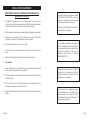
MOLNAR
TWO-POST HOIST
MF 1705-85A/3T
MANUFACTURED BY:
0124
MOLNAR ENGINEERING PTY. LTD.
A.B.N. 54 007 740 794
16-20 Coglin Street, Brompton, S.A. 5007 AUSTRALIA
1-11 Wood Avenue, Brompton, S.A. 5007 AUSTRALIA
Telephone: (08) 8346 6893, (08) 8346 6894, (08) 8346 8006
Fax: (08) 8346 0097, Email: [email protected]
INSTALLATION, OPERATION
& MAINTENANCE MANUAL
CERTIFICATION
I hereby certify that the hoist has been checked and is in a safe operating
condition and that the purchaser/operator has been duly instructed in the
operation thereof.
OPTIONAL 240 VOLT SINGLE PHASE
MINIMUM REQUIREMENTS FOR ELECTRICAL CONNECTION OF
MOLNAR HOISTS
Important: All installations should be carried out by suitably
qualified persons. Failure to comply may void warranty.
The following information is a guide only based on the
latest standards as set out in AS/NZS 3000, for installations
outside of Australia & New Zealand refer to local
standards/regulations.
Circuit Breakers should be of “D” curve type (motor start,
high inrush current) - Ratings given as a maximum for
circuit & motor protection based on DOL selection guide.
Purchaser . . . . . . . . . . . . . . . . . . . . . . . . . . . . . .
Model No . . . . . . . .MF
. . .1705-85A/3T
...................
Serial No . . . . . . . . . . . . . . . . . . . . . . . . . . . . . . .
Date . . . . . . . . . . . . . . . . . . . . . . . . . . . . . . . . . .
Voltage operating range: -6% to +10% of motor
nameplate Voltage.
Motor Voltage 240V Operation range 225V to 264V.
Cable sizes are given as a guide only for a maximum
cable length to 30m. Longest cable runs and in area
where supply voltage is below motor voltage,
calculation should be made to ensure Voltage Drop will
not fall below minimum operating voltage.
When installed motors must be tested under Full Load checking
Voltage at motor terminals.
Installation by . . . . . . . . . . . . . . . . . . . . . . . . . . .
Address . . . . . . . . . . . . . . . . . . . . . . . . . . . . . . .
......................................
Name . . . . . . . . . . . . . . . . . . . . . . . . . . . . . . . . .
Motor 2.2kW 240V Single phase model CWC3640F
Full Load Current
Min Cable Size
Circuit Breaker
12.4 Amps
2.5mm 2 core + earth
1 phase 32 Amp 10kA
Recommended Clipsal 4CB132/10 or equivalent
Signature . . . . . . . . . . . . . . . . . . . . . . . . . . . . . .
Date . . . . . . . . . . . . . . . . . . . . . . . . . . . . . . . . . .
Page 25
INSTALLATION REQUIREMENTS
INSTALLER MUST CHECK THE FOLLOWING LIST WHEN INSTALLING A
MOLNAR TWO-POST HOIST
1.
A suitable floor where the hoist is to be bolted down must have a level
surface to ensure the hoist base frames lie flat. When the hoist is bolted down
check all nuts and bolts to ensure they are correctly tightened.
2.
Check wire ropes and sheaves for possible transport damage or dislocation.
3.
When power is connected to the hoist terminal box the motor must rotate
clockwise. If hoist will not lift exchange wires on two phases.
4.
Check safety mechanism for loose nuts or bolts.
5.
Check operation of safety mechanism on both sides, then test hoist with
load.
6.
Recheck hoist operation. Demonstrate the hoist to the operator.
7.
Very important
7.1 Instruct operator how to use the hoist, how the safety mechanism works and
where to place lifting pads when lifting vehicles.
7.2 Point out maintenance requirements on wire ropes and that they should be
checked monthly.
No person should be permitted to operate
the MOLNAR TWO-POST HOIST without first
studying the operating instructions on page
7 and safety precautions on page 16.
This manual should be kept in a safe place
and referred to as necessary.
The installation requirements on page 24
must be completed and the certificate on
the inside back cover must be signed by the
installer. The guarantee card must be
completed and returned to MOLNAR
ENGINEERING PTY. LTD.
In tropical and steam cleaning conditions to
prevent rust in the cylinder raise the hoist to
full height and leave it there when not in use
overnight and on weekends.
7.3 Point out that by law, the operator and/or owner are responsible for the
maintenance and safe operation of the hoist.
8.
When all the above points are checked the certificate must be signed by the
installer.
Page 24
This vehicle hoist is not designed to be used
for steam cleaning nor to be installed in the
open exposed to the elements. Vehicle
hoists installed under such conditions are not
covered by our guarantee.
Page 1
DOOR PROTECTOR INSTALLATION PROCEDURE
FIG 4
INSTALLATION PROCEDURE
MF 1705-85A/3T
MF 1705-85A/3T
complies fully with the
Australian Standard
1418.9 - 1987
Page 2
1.
Place door protector into position as shown in above drawing. Make sure the
door protector ends are flush with the edge.
2.
Push the protector in at the bend, until the holes in the bracket and the
carriage line up.
3.
Screw the M6 bolt into position as shown in diagram.
Page 23
CONTENTS
INSTALLATION INSTRUCTIONS
Introduction . . . . . . . . . . . . . . . . . . . . . . . . . . . . . . . . . . . . . . . . . . . . . . . . . . . . . . 4-5
Hoist Base Requirements . . . . . . . . . . . . . . . . . . . . . . . . . . . . . . . . . . . . . . . . . . . . . 6
Operating Instructions . . . . . . . . . . . . . . . . . . . . . . . . . . . . . . . . . . . . . . . . . . . . . . . 7
Maintenance . . . . . . . . . . . . . . . . . . . . . . . . . . . . . . . . . . . . . . . . . . . . . . . . . . . . . 8-9
Lubrication Procedures for Molnar 2 Post Hoists . . . . . . . . . . . . . . . . . . . . . . . . . . . 9
Replacement Parts List . . . . . . . . . . . . . . . . . . . . . . . . . . . . . . . . . . . . . . . . . . . 10-11
Parts Identification . . . . . . . . . . . . . . . . . . . . . . . . . . . . . . . . . . . . . . . . . . . . . . . 12-13
Accessories . . . . . . . . . . . . . . . . . . . . . . . . . . . . . . . . . . . . . . . . . . . . . . . . . . . . . . . 14
Hydraulic Cylinder Replacement . . . . . . . . . . . . . . . . . . . . . . . . . . . . . . . . . . . . . 15
Safety Precautions . . . . . . . . . . . . . . . . . . . . . . . . . . . . . . . . . . . . . . . . . . . . . . . . . 16
Fault Chart . . . . . . . . . . . . . . . . . . . . . . . . . . . . . . . . . . . . . . . . . . . . . . . . . . . . . . . 17
Wiring Diagram . . . . . . . . . . . . . . . . . . . . . . . . . . . . . . . . . . . . . . . . . . . . . . . . . . . 18
Hydraulic Circuit Diagram . . . . . . . . . . . . . . . . . . . . . . . . . . . . . . . . . . . . . . . . . . . 19
Installation Instructions . . . . . . . . . . . . . . . . . . . . . . . . . . . . . . . . . . . . . . . . . . . . 20-24
SPECIFICATIONS
FIG 3
INSTALLATION PROCEDURE
1.
Bolt locking bracket (1) to pick-up arm using 7/16 U.N.F. bolts.
2.
Locate arm (7) in pivoting bracket.
3.
Slide locking lug (2), followed by spring (6), followed by another locking lug
(2), along arm (7).
4.
Locate locking lugs (2) in locking bracket (1).
5.
Push pins (3) into position and secure using circlips.
6.
Push pin (10) into position and secure using circlip (11).
7.
Place foot pedal (9) over locking bracket (1).
8.
Push shaft (8) through foot pedal and locking bracket and secure with E clip
(12).
Width between columns
2650mm
Overall width
3250mm
Overall height
2770mm
Overall length
1200mm
Width base plate
575mm
Height of base plate
55mm
Maximum raised height
1900mm
Minimum lowered height
90mm
Length of front lifting arms maximum
1020mm
minimum
610mm
Lifting time (working height)
approx. 20 secs
Electric motor - 3 phase, 2.2kw, 2700 rpm, 415 volts, 50 hertz
(optional)
- Single phase, 2.2kw, 2850 rpm, 240 volts, 50 hertz
Hoist mass
- 722kg
Wire rope
- 13mm diameter 6 x 29FW(14/7+7F/1) IWRC
RHOL B1770
minimum breaking strength 107kn
Hydraulic oil
- Castrol Hyspin AWH46, Shell Tellus T46,
Mobil DTE 25, BP Bartran HV46 or equivalent
Capacity
- 3000kg (3.0 tonnes)
The Manufacturer reserves the right to alter these features and specifications without notice.
Page 22
Page 3
INTRODUCTION
INSTALLATION INSTRUCTION
Here is the MOLNAR TWO-POST HOIST, a space saving wheel-free hoist and its
many advantages.
It has been purposely designed for space saving and to give versatility and
profitability to the largest garage and smallest service station. Safe, strong, simply
built to give years of trouble-free service. The MOLNAR TWO-POST HOIST embodies
many features that makes it the most up-to-date equipment for quicker and more
profitable service.
SAFE AND EFFICIENT OPERATION
Due to an electro hydraulic system which gives years of trouble free service.
Raising and lowering of vehicle is controlled by hydraulics, plus built-in
mechanical safety against any failure plus deadman control mounted on the
hydraulic column.
INSTALLATION
The MOLNAR TWO-POST HOIST is fast and simple to install only 10 bolts needed for
a suitable floor. No costly excavation. It is also ideal for upper floor level where
excavation is not possible. The hoist is surface mounted a feature which means
lower overall cost. Compared with similar-priced hoists the MOLNAR TWO-POST
HOIST can be quickly, easily and economically re-sited.
Page 4
Page 21
INSTALLATION INSTRUCTION
1.
2.
3.
4.
5.
6.
7.
8.
9.
10.
11.
12.
13.
14.
15.
16.
17.
18.
19.
20.
21.
22.
23.
24.
25.
26.
Position hoist to installation position.
Remove wooden box.
Cut straps holding posts together.
Undo the packing legs securing bolts (2 per side).
NOTE: The 4 packing legs securing bolts are to be fitted into the base plates
of the posts. The nuts are to be discarded.
Cut strap holding packing legs to hoist.
Lift hoist off floor, and remove packing legs..
Place hoist on floor.
Swing out tops of both posts, horizontally anti clockwise right hand with motor
first and place on wooden blocks with top of post 500mm from base. Refer
Figure 1.
Remove bolts from base.
Lift right hand post into position and bolt to base.
Repeat with left hand post.
Cut 2 straps marked “DO NOT CUT THIS STRAP UNTIL THIS POST IS IN AN
UPRIGHT, BOLTED-DOWN POSITION”.
Remove arms, door protectors and packet of locking arms.
Remove checker plates.
Position correctly and bolt down (page 6).
Pour oil in tank and connect power.
Raise hoist to approx. waist level.
Check that cylinder is seated correctly (with a 2mm gap when viewed
through inspection hole above bottom right sheave). If cylinder not seated
correctly adjust its position with bent wire until it drops and seats under its own
weight. Refer Figure 2.
Install locking arms. Refer Figure 3.
Install checker plates.
Attach door protectors. Refer Figure 4.
Apply lubricant on wear pad tracks and roller tracks.
Install covers on both posts.
Left hand side carriage approx. 25mm higher than right hand carriage, to
allow the cable to bed in.
Final Test: Drive a car over hoist base plate and simultaneously observe the
top of both posts for any movement. If there is any movement you must
check dyna bolts and shims (Refer page 6) until the car can be driven over
hoist base plate and no movement in the post is observed.
Clean the hoist of anit-corrosion spray.
Page 20
INTRODUCTION
FOR SPEEDIER SERVICE
With the MOLNAR TWO-POST HOIST maximum accessibility is assured. No
cumbersome beams or cross-sections impede the operator in any way, giving the
hoist unlimited advantages, when used for unit replacement. With this lifting
method the suspension springs are relaxed, facilitating lubrication and repair
work. Wheel service, brake adjustment, washing underbody spraying or sealing or
any underbody repairs can be speedily carried out.
EASY TO OPERATE
The MOLNAR TWO-POST HOIST is operated with the greatest of ease. The
telescopic adjustable arms and contact pads are easily placed in position by one
man. The operator has full confidence due to the mounting of the arms and the
area of the chassis which can be contacted. The vehicle is immediately wheelfree and stable at any height.
Page 5
FLOOR REQUIREMENTS FOR HOIST BASE
HYDRAULIC CIRCUIT DIAGRAM
For correct installation of the Hoist the floor must be flat and level. A level
tolerance between post of 10mm is allowable. Check with straight edge and spirit
level. See Fig 1.
In situationss where the floor is too soft a reinforced concrete slab, 3850 x 2200 x
120mm should be laid (Cement 1, Sand 3, Metal 6). If the floor is solid but not quite
level, it may be compensated for with steel shims. SeeFig 2.
If shims are used they must also be placed at the points A,B,C,D and E as required
to maintain the level and stability of the Hoist. See Fig 3.
A concave or convex section to be used as a floor for the Hoist base may be
levelled with the use of sand and cement mix. See Fig 4. (Cement 1, Sand 5).
20mm dyna bolts x 82mm length with a thread size 16mm are recommended for
fastening down. This may differ in some States.
Page 6
Page 19
WIRING DIAGRAM
OPERATING INSTRUCTIONS
WIRING TO THIS UNIT TO COMPLY WITH AS 3000
1.
Drive on - car to be centred.
2.
Place the four pads under edge of car
fore and aft at jack points.
3.
Press starter button and raise car to
required height. Do not go under car
until load rests on safety.
4.
When car reaches maximum height
limit switch will come into operation
and stop hoist. When hoist has
stopped, pull release lever until load
rests on safety.
5.
During the lifting of the car a clicking
sound should be noticeable which
indicates the safety mechanism is
operating. If this sound is not heard,
immediately cease using the hoist and
call an authorised service agent.
6.
The following steps are to be taken
when lowering the hoist. Raise hoist
approximately 20mm. Push safety
catch to the OFF position.
7.
Pull release lever down and lower hoist.
8.
If car is to be worked on at an
intermediate position re-apply safety
catch.
9.
To lower to ground level, raise car
approximately 20mm. Release safety
catch and lower.
10. WARNING. Do not go under vehicle
under any circumstances while vehicle
is being lifted or lowered.
Page 18
Page 7
MAINTENANCE
CHECK DAILY
Check safety mechanism to see that it functions properly.
CHECK MONTHLY
1. Safety mechanism operation.
2. Condition of sheaves, shafts and shaft locks.
3. Condition of wire ropes.
4. Overall cleanliness.
5. Clean tracks of dry lubricant and re-apply lubricant on wear pad tracks and
roller tracks.
CHECK 6 MONTHLY
1. State of swivel arms.
2. Oil leaks from cylinder.
3. Oil leaks at pipe joints.
4. Anchor bolts.
5. Wire ropes.
CABLE ADJUSTMENT
If the long cable has stretched provision is provided for cable adjustment by
winding the cable nut up.
Page 8
FAULT CHART
FAULT
PROBABLE CAUSE
REMEDY
Leakage of oil at joints.
Loose joints in the high pressure
pipes.
Inspect the piping and tighten
joints.
Leakage of oil at top
of hydraulic cylinder.
Worn packing seal in hydraulic
cylinder.
Replace packing seal or
cylinder.
Lack of lifting power.
Release valve not seating properly
or a loose connection inside of tank.
Rotate valve stem one full turn.
Tighten connections.
Obstruction in suction side of pump.
Remove and clean out tank,
refill with fresh oil.
Release valve not seating properly.
Loose joints in oil line in the tank
or outside.
Rotate release valve stem one
full turn or replace. Tighten joints.
If non-return valve is not seated
correctly return oil pressure will
rotate electric motor.
Check for dirt or possible damage
to valve seat.
Clean or replace.
Hoist does not respond
to operation switch.
Power supply to motor is interrupted.
Motor turning in opposite direction.
Cables either cut or damaged.
Check main fuse, power source,
magnet switch and terminal relay.
Interchange 2 terminals in
3 phase circuit.
Damaged cable.
Worn sheaves and sheave pins
or bushes.
Replace sheaves, sheave
pins and cables and bushes.
Carriage shuddering
in lifting and lowering
mode.
Lack of lubricant on wear pad
tracks causing wear
pads to grip instead of sliding.
Clean and re-apply
lubricant on wear pad tracks.
Excessive side
movement of
carriage.
Worn wear pads.
Replace wear pads.
Hoist fails to stay up.
Page 17
SAFETY PRECAUTIONS
DON’T
1.
Do not try to lift anything beyond the maximum capacity 3000 Kg.
2.
Do not operate without first ascertaining the safety of people and
equipment in the area.
3.
Do not go under car or make adjustments while hoist is in operation.
4.
Do not try to adjust bearer pads engaged to jack points while the hoist is in
operation.
5.
Do not fail to inspect safety devices periodically to see they are in proper
working condition.
6.
Do not make unauthorised changes to safety equipment. In emergency
consult this manual or your local dealer.
7.
Do not oil or grease swivel arms as they should not move in or out while hoist
is operating.
8.
Do not fail to protect operating switch from water if the hoist is used for car
washing. Ropes should be smeared with water-resistant grease.
9.
Do not try to adjust relief valve as it has been set at maximum operating
efficiency.
10. Do not turn off mains power while hoist is operating.
11. Do not force safety lever into the off position while weight is resting on safety.
MAINTENANCE
YEARLY
Service and safety inspection on the hoist must be performed by a competent
person. This inspection must be recorded. If the 12 monthly service and safety
inspection is not performed, the warranty is null and void.
NOTE: Yearly service must include removal of rollers and pulleys to inspect, clean
and lubricate bushes and pins.
2 YEARLY
Hydraulic oil and filter should be replaced. Fill Oil Tank to Oil Level Line with Shell
Tellus T46 oil, Mobil DTE25 oil, Castrol Hyspin AWH46 oil, BP Bartran HV46 oil or
equivalent.
WIRE ROPE INSPECTION
Wire ropes must be inspected by a COMPETENT person. Inspect for wear, rust and
broken wires. Ropes are to be discarded according to the criteria.
Wire rope must be replaced if:
a. At any point the visible number of broken wires exceeds 10 in any length of
rope equivalent to 20 times the rope diameter i.e. for 13mm diameter rope 10
broken wires in 260mm of cable.
b. A strand of wire is broken.
c. A rope has been physically damaged by crushing or deforming.
LUBRICATION PROCEDURES FOR MOLNAR 2 POST HOISTS
It is the Hoist Owner’s responsibility and Duty of Care to maintain the Hoist as per
the Maintenance Schedule in the Hoist Owner’s Manual.
All Tracks must be lubricated regularly. (Both Posts.)
12. Do not attempt to operate the hoist from under vehicle.
This includes the roller tracks behind the covers. (Both Posts.)
Molnar Engineering suggest that the rear tracks be heavily lubricated. You may
use grease on the rear tracks because the rear tracks are fully covered by the
Hoist covers.
The 2 Front Tracks and the 2 Side Tracks also have to be regularly lubricated. (Both
Posts.)
Molnar Engineering suggests Teflon or Silicon Sprays may be used (because the
Hoist will be totally clean and there is no fear of lubricant accidentally being
rubbed onto clothing).
“TAC 2” lubricant may also be used.
Page 16
Page 9
REPLACEMENT PARTS LIST
HYDRAULIC CYLINDER REPLACEMENT
85A-AA
85A-A-218
Basemember and floor plate assembly
Floorplate . . . . . . . . . . . . . . . . . . . . . . . . . . . . . . . . . . . . . . . . . . . . . . (2)
85A-BB
85A-B-14
85A-B-16
85A-B-81
85A-B-83
85A-B-84
85A-B-119
85A-B-151
Right hand post assembly
Cover
Base plate anchoring bolt . . . . . . . . . . . . . . . . . . . . . . . . . . . . . . . . (7)
Top plate
Large power unit carrier bracket
Small power unit carrier bracket
Right hand post
Cover mounting bracket
1.
Disconnect power.
2.
Lower carrier.
3.
Remove cover.
4.
Disconnect hydraulic pipe at top of post.
85A-CC
85A-C-14
85A-C-17
85A-C-40
Left hand post assembly
Cover
Left hand post
Cover mounting bracket
5.
Unbolt and remove motor/tank assembly from top of post.
6.
Disconnect twin ropes by removing safety mechanism lever and spring
retainer and slide rope terminations out.
85A-DD
85A-D-9A
85A-D-10
85A-D-11
85A-D-13
85A-D-24
85A-D-25
85A-D-36
85A-D-37
85A-D-38
85A-D-39
85A-D-63
85A-D-66A
85A-D-67A
85A-D-72
85A-D-75
85A-D-77
85A-D-131
Cables and pulleys
Pulley assembly
Pulley pin . . . . . . . . . . . . . . . . . . . . . . . . . . . . . . . . . . . . . . . . . . . . . . (2)
Pulley pin retaining bolt . . . . . . . . . . . . . . . . . . . . . . . . . . . . . . . . . . . (2)
Long cable
Cable spring sleeve
Cable spring
Cable nut
Pulley pin retaining bolt
Pulley pin
Top left pulley bracket
Cable retaining cap . . . . . . . . . . . . . . . . . . . . . . . . . . . . . . . . . . . . . (2)
Pulley assembly
Short cable . . . . . . . . . . . . . . . . . . . . . . . . . . . . . . . . . . . . . . . . . . . . (2)
Pulley pin
Cable spring cap
Cable spring cap
Short cable spring
7.
Remove sheave assembly.
8.
Unbolt post and lay down with exposed sheave facing upwards.
9.
Ensure hydraulic pipe disconnected is inside post and then slide
cylinder/pipe out of post.
85A-EE
85A-E-108
85A-E-108A
85A-E-220
85A-E-221
85A-E-1S
Hydraulic cylinder assembly
Outside cylinder
Hydraulic cylinder assembly
Straight adaptor
Elbow adaptor
Cylinder seal kit
85A-FF
85A-F-96
85A-F-101TP
85A-F-101SP
85A-F-163A
85A-F-167
85A-F-197
85A-F-208A
Power pack assembly
Coupling assembly
Electric motor (415v)
Electric motor kit (240v)
Power pack assembly
Hydraulic pump
Lowering handle
Control valve assembly
85A-HH
85A-H-82
85A-H-85
Starter assembly
Starter bracket
Limit switch bracket
Page 10
Procedure
10. To remove piston take out circlip and apply compressed air to inlet (with
caution). Inspect cylinder wall for rust or scoring. If scored the cylinder wall
must be re-honed or the malfunction will continue. If rusted it must be rehoned or replaced.
Page 15
ACCESSORIES AVAILABLE FROM MOLNAR ENGINEERING
Optional
EP02 Elevated
Extension Pads enables
easy pickup for vans
and 4-wheel drives.
Optional
J3AB Stabilizing Pads
prevents pickup pads from
slipping. Stabilizes the vehicle
from rocking movement.
MOLNAR ENGINEERING
recommends to all new owners the
purchase of our accessories to
cover all working situations
Featuring
JJ3 Large Pickup Pads.
Rubber size - large 140mm.
REPLACEMENT PARTS LIST
85A-H-94
85A-H-153
85A-H-155
85A-H-157
Limit Switch
Junction box
Saddles . . . . . . . . . . . . . . . . . . . . . . . . . . . . . . . . . . . . . . . . . . . . . . . (3)
Starter box
85A-JJ
85A-J-49
85A-J-50
85A-J-52
85A-J-53
85A-J-54
85A-J-55
85A-J-57*
85A-J-58
85A-J-59
85A-J-60
85A-J-61
85A-J-354
85A-J-355
85A-J-356
85A-J-357
85A-J-85357
85A-JJ3
85A-J3AA
85A-J3AB
85A-J-8550*
Lifting arm assembly . . . . . . . . . . . . . . . . . . . . . . . . . . . . . . . . . . . . . (4)
Locking rod pivot pin
Lifting arm pivot pin
Pick-up pad
Extension arm
Telescopic arm
Locking arm pivot pin . . . . . . . . . . . . . . . . . . . . . . . . . . . . . . . . . . . . (2)
Locking arm bracket
Locking plate . . . . . . . . . . . . . . . . . . . . . . . . . . . . . . . . . . . . . . . . . . . (2)
Spring
Locking arm bracket bolt . . . . . . . . . . . . . . . . . . . . . . . . . . . . . . . . . (2)
Locking rod
Foot pedal
E-Clip
Foot pedal shaft
Foot operated locking arm bracket
Foot operated locking arm kit (for four arms)
Pick-up pad
Elevated pad
Stabiliser pad
Locking arm kit
85A-KL
85A-KL-2
85A-KL-27
85A-KL-30
85A-KL-31
85A-KL-32
85A-KL-35
85A-KL-42R
85A-KL-216R
85A-KL-217A
Left hand carriage assembly
Left hand carriage
Safety toggle spring . . . . . . . . . . . . . . . . . . . . . . . . . . . . . . . . . . . . . (2)
Safety linkage . . . . . . . . . . . . . . . . . . . . . . . . . . . . . . . . . . . . . . . . . . (2)
Safety toggle
Safety toggle
Toggle shaft
Wear pad . . . . . . . . . . . . . . . . . . . . . . . . . . . . . . . . . . . . . . . . . . . . . . (4)
Roller . . . . . . . . . . . . . . . . . . . . . . . . . . . . . . . . . . . . . . . . . . . . . . . . . . (4)
Washer (Acetal) . . . . . . . . . . . . . . . . . . . . . . . . . . . . . . . . . . . . . . . . (16)
85A-KR
85A-KR-3
85A-KR-140
85A-KR-125
85A-KR-126
85A-KR-152
Right hand carriage assembly
Right hand carriage
Safety pivot arm
Safety toggle
Safety toggle
Safety on/off arm assembly
85A-LL
85A-L-79
85A-L-142
85A-L-145
85A-L-146
85A-L-148
Safety control assembly
Linkage
Linkage
Activator
Safety actuating assembly
Activating spring
* Superseded
Page 14
Page 11
Page 12
MODEL MF 1705-85A/3T
Page 13