1
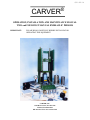
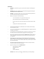
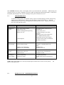
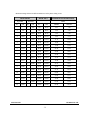
$50.00 US
CARVER
®
OPERATION, INSTALLATION AND MAINTENANCE MANUAL
TWO and FOUR POST MANUAL HYDRAULIC PRESSES
IMPORTANT:
PLEASE READ CAREFULLY BEFORE INSTALLING OR
OPERATING THIS EQUIPMENT
CARVER, INC.
1569 Morris Street, P.O. Box 544
Wabash, IN 46992-0544
PH: 219-563-7577 FAX: 219-563-7625
NOTE: Performance figures stated in this manual are based on a Standard Atmosphere of 59 degrees F. (15 degrees
C.) and 29.92" Hg (10,331 Kg/m²) at sea level and using 50 Hz electrical current. All of these factors are important
considerations when selecting a hydraulic press. CARVER, INC. can advise you on proper selection and sizing of
systems for the operating environment at your location.
CARVER, INC. is committed to a continuing program of product improvement. Specifications, prices, appearance,
and dimensions described in this manual are subject to change without notice.
CARVER, INC. 1996
All Rights Reserved.
Part #: 1520.2&4PSTUSCE
Rev. 03
Effective: 04/15/96
TABLE OF CONTENTS
SECTION
ONE
PAGE
INTRODUCTION
1-1
1-2
1-3
TWO
Introduction ............................................................................................................................................. 1
CARVER Accessories............................................................................................................................ 1
Customer Service..................................................................................................................................... 1
SAFETY
2-1
2-2
2-3
2-4
2-5
THREE
Safety Considerations.............................................................................................................................. 2
General Responsibility ............................................................................................................................ 3
Operator Responsibility........................................................................................................................... 3
Mold Setters Responsibility .................................................................................................................... 5
Maintenance Responsibility .................................................................................................................... 6
INSTALLATION
3-1
3-2
3-3
3-4
3-5
3-6
3-7
3-8
3-9
3-10
FOUR
Two Post Press Description .................................................................................................................... 8
Four Post Press Description .................................................................................................................... 9
Laminating Press Description ............................................................................................................... 11
Installation ............................................................................................................................................. 12
Setting Up .............................................................................................................................................. 12
Gauge Information ................................................................................................................................ 12
Ram Force Calculation.......................................................................................................................... 13
Filling the Oil Reservoir........................................................................................................................ 13
Gases or Dust Removal ......................................................................................................................... 13
Connecting Utilities............................................................................................................................... 14
OPERATION
4-1
4-2
4-3
4-4
4-5
FIVE
Operator Safety...................................................................................................................................... 16
Operating the Hydraulic Press .............................................................................................................. 17
Daylight Adjustment ............................................................................................................................. 18
Operating Presses Equipped with Heated Platen.................................................................................. 20
Laminating Presses................................................................................................................................ 21
MAINTENANCE
5-1
5-2
5-3
5-4
SIX
TITLE
Troubleshooting..................................................................................................................................... 27
Hydraulic Unit - Air Bleed Procedure .................................................................................................. 28
Electrical ................................................................................................................................................ 28
Mold Size versus Tonnage Chart.......................................................................................................... 29
HYDRAULIC OIL INFORMATION
30
SEVEN
ACCESSORY EQUIPMENT
EIGHT
CARVER, INC. PARTS and SERVICE INFORMATION
8-1
8-2
NINE
31
Technical Assistance ............................................................................................................................. 32
Returned Material Policy....................................................................................................................... 32
WARRANTY PROCEDURES
9-1
9-2
Warranty Returns .................................................................................................................................. 33
Warranty Statement............................................................................................................................... 33
TEN
PICTOGRAM/TAG INFORMATION
APPENDIX
Hydraulic Unit Drawings - 12 ton, 25 ton
Hydraulic Unit - Section View (Typical)
Hydraulic Unit Drawing - 30 ton
Gauge Union Coupling Assembly - Typical
Hydraulic Cylinder - 30 ton
Electrical Symbol Cross Reference
Electrical Drawings
Press Assembly Drawings
34
SECTION ONE
1-1
INTRODUCTION
INTRODUCTION
We are pleased to supply CARVER Laboratory Equipment for your facility. CARVER presses are used in
many applications including research and development, specialized or low volume
development
ituations, and quality testing. Thousands of presses are in use all over the world for numerous applications in
the chemical, physical, biological, and mechanical fields wherever pressing is
required.
1-2
ACCESSORIES
CARVER, INC. offers a variety of standard accessories for your press including Heated Platens,
Heating
and Cooling, or Cored Platens, Test Cylinder Outfits, French Pressure Cells, Swivel Bearing Plates, and Cage
Equipment. All original CARVER accessories are designed and manufactured by CARVER, INC. These
accessories ensure precise results for many applications, such as oil determination tests in food products,
crushing analysis on cement core samples, molding of plastic quality control specimens, and preparing KBr or
tracer pellets, etc.
Each accessory allows you to tailor the hydraulic press to your specific application. In addition to
standard items, we also manufacture custom presses and accessories for unique applications.
1-3
these
CUSTOMER SERVICE
The intent of this manual is to familiarize the operator and maintenance personnel with this equipment and
help your organization get the maximum service from your press. If you have any questions regarding
installation, service, repair, custom equipment or applications, please do not hesitate to call or write for the
information required. Prices for presses, accessories, or repair parts will be furnished promptly on request.
NOTICE:
If you desire to use a press for an application other than that for which it was purchased, please
contact our factory to verify compatibility of the equipment with the new process. Misapplication of
the equipment could result in injury to the operator or damage to the equipment.
1
SECTION TWO
2-1
SAFETY
SAFETY CONSIDERATIONS
The terms NOTICE, CAUTION, WARNING, and DANGER have specific meanings in this
manual.
A NOTICE is used to indicate a statement of company policy directly or indirectly related to the
safety of personnel or protection of property.
A CAUTION indicates a potentially hazardous situation which, if not avoided, may result in minor or
moderate injury.
A WARNING indicates a potentially hazardous situation which, if not avoided could result in death or
serious injury.
A DANGER indicates an imminently hazardous situation which, if not avoided, will result in death or
serious injury. This word will be limited to the most serious situation(s).
The term IMPORTANT emphasizes areas where equipment damage could result, or provides
additional information to make a step or procedure easier to understand. Disregarding information
IMPORTANT would not be likely to cause personal injury.
marked
REPORTING A SAFETY DEFECT
NOTICE:
If you believe that your equipment has a defect, which could cause injury, you should immediately
discontinue its use and inform CARVER, INC., at our address listed in this manual.
The principle factors, which can result in injury, are:
1.
Failure to center the work over the ram in the platen area, resulting in eccentric loading,
tilting, and possible movement of the work piece, which can then become a projectile;
2.
Failure to level the top head of the press after it has been repositioned, which can produce
the same results as in Number One, above;
3.
Fracture of a specimen or part of the apparatus due to overload, resulting in flying
fragments;
4.
Occasional squirting of liquid from a pressed specimen;
5.
Contact with hot plates or heated apparatus can produce severe burns.
2
2-2
GENERAL RESPONSIBILITY
NO MATTER WHO YOU ARE...
Press safety is important. Press owners, operators, mold setters, and maintenance personnel must
that every day, all day, safety is a vital aspect of their jobs.
If your main concern is productivity, remember this.
involving a press:
realize
Loss of production always follows an accident
*
loss of a skilled operator (temporarily or permanently)
*
breakdown of shop morale
*
costly damage to press and/or tooling
*
down time.
An effective press safety program is not only humanitarian, but is also economically sound.
Organize a safety committee or group, and hold regular meetings. Promote this group from the
management level. Through this group, the safety program can be continually reviewed,
maintained, and improved. Keep minutes or a record of the meetings.
Hold daily press inspections in addition to regular maintenance checks. You will keep your presses safe for
production and exhibit your commitment to safety.
Please read and use this manual as a guide to molding machine safety. This manual contains safety warnings
throughout, specific to each function and point of operation. It is to promote and increase safe press operation
in your company.
2-3
OPERATOR RESPONSIBILITY
It doesn't end with fast and efficient production. The press operator usually has the most daily
contact with the press and intimately knows its capabilities and limitations.
Plant and personal safety is sometimes forgotten in the desire to meet incentive rates, or through a
casual
attitude toward machinery formed over a period of months or years. Your employer probably has established a
set of safety rules in your workplace. Those rules, this manual, or any other safety information will not keep
you from being injured while operating your press.
ONLY YOU can make safety work for you by constantly thinking about what is safe and what is not. It is
often the "just once" that a press operator reaches into a press to remove or adjust material, or rest a hand in
the ram area while talking to a co-worker that results in serious injury.
Learn and always use safe press operation. Cooperate with co-workers to promote safe practices.
Immediately report any potentially dangerous situation to your supervisor or appropriate person.
3
REMEMBER:
*
NEVER place your hands or any part of your body in the mold area or other dangerous
locations.
*
NEVER operate, service, or adjust press or molds without the appropriate training and
first reading and understanding this manual.
*
NEVER try to pull material (either a part or scrap) out of the mold with your hands! If a
part sticks in the mold, stop the press and call your supervisor.
*
Before you start the press, check the following:
-
remove all maintenance crew equipment from the press area;
-
make certain safety blocks are removed from the mold;
-
be sure no objects (tools, nuts, bolts, clamps, bars) are laying in the press clamp
area;
-
carefully look for obstructions left in the mold;
*
If your press has been inoperative or unattended, even for a moment, check all settings
before starting the next cycle.
*
If your press has multiple platens, be sure ALL floating platens are completely open before
reaching into the clamp area.
*
At the beginning of your shift and after breaks, cycle the press several times to verify that
the controls, press parts, molds and auxiliary equipment are functioning properly.
*
Keep all safety guards in place and in good repair. NEVER attempt to bypass, modify, or
remove safety guards. Such alteration is not only unsafe, but will void the warranty on
your equipment.
*
When changing press control settings to perform a different mode of operation, be sure
selector switches are correctly positioned. Test cycle the press to verify it will operate as
planned. Locking selector switches should be adjusted only by authorized persons and the
keys removed after setting.
*
Do not talk to others while operating a press. If you must talk, stop the press and step
away from it until the conversation is completed.
*
Report the following occurrences IMMEDIATELY:
-
*
unsafe operation or condition
unusual press action
leakage
improper maintenance
NEVER stand or sit where you could slip or stumble into the press while operating it.
4
*
DO NOT wear loose clothing or jewelry, which can be caught while operating a press. Also
cover or tie back long hair.
*
DAILY clean the press and surrounding area, and inspect the machine for loose, missing,
or broken parts.
*
Shut off power to the press when it is not in use. Lock the control panel or disconnect
switch in the OFF position or unplug press from power source.
2-4
MOLD SETTERS RESPONSIBILITY
What they sometimes forget is their own safety during the installation or removal of a mold. To
successfully perform this job, the mold setter must gain a good working knowledge of the press,
molds, materials, and must know how to use a mold truck and other handling equipment.
Technical knowledge is not enough. The mold setter's sense of personal safety is crucial. Installing and testing
mold guards and point of operation safety devices is as important as properly mounting the mold to the press.
DON'T FORGET
*
NEVER place your hands or other part of your body within the mold area unless the power
is OFF to the press.
*
If the press has multiple openings, be sure that ALL floating platens are completely open
before installing tooling.
*
NEVER install, adjust, or remove molds without the appropriate training and first reading
and understanding this manual.
*
NEVER move molds or service the press with the electric power on or without blocks in
place.
*
Clean bolsters, platens, and molds before installing the mold set. Dirt or foreign materials
can cause misalignment, resulting in operator injury and/or press and mold damage.
*
ALWAYS lock out the control panel or disconnect switch in the [OFF] position to prevent
unauthorized use or accidental starting of the press.
*
NEVER install worn or damaged molds. Make sure the clamp pressure is properly
adjusted, relative to the mold size (refer to the "Mold Size vs. Tonnage"
chart in the Maintenance Section of this manual.
*
Secure all molds to the mold truck before you move them.
*
When clamping molds to the press, use the appropriate number and size of clamps to hold
the molds securely (please consult your mold manufacturer if in doubt about appropriate
clamp usage).
*
After installing molds, make all necessary adjustments BEFORE cycling the press.
5
*
Make sure all persons are clear of the press and remove all objects from mold area (tools,
nuts, bolts, clamps, bars) before cycling.
*
Watch the press in operation to make sure molds and equipment are working properly.
*
Before the press is used for production, replace all guards and applicable safety devices to
protect the operator.
*
If the press operator is required to load or unload parts, provide safe and appropriate tools
(cotton gloves, safety tongs, vacuum lifters, pliers, or other mechanical devices) for his or
her use.
*
When changing press control settings to perform a different mode of operation, be sure
selector switches are correctly positioned. Test cycle the press to verify it will operate as
planned. Locking type selector switches should be adjusted only by authorized persons and
the keys removed after setting.
*
NEVER change selector switches on the press during a cycle.
*
If the press has been inoperative or unattended, even for a moment, check all settings
before starting the next cycle.
*
Report the following occurrences IMMEDIATELY:
-
2-5
unsafe operation or condition
unusual press action
leakage
improper maintenance
MAINTENANCE RESPONSIBILITY
Safety is essential to the good health of both man and machine. If you are a maintenance worker, you must
make safety a priority in order to effectively repair and maintain press equipment.
BEFORE REMOVING, ADJUSTING, OR REPLACING PARTS ON A MACHINE, REMEMBER
TO:
*
BLEED all pressure from system components (refer to the Maintenance Section of this
manual.)
*
TURN OFF all air, water, and hydraulic pressure supplies and all accessory equipment at
the machine.
*
DISCONNECT AND LOCK OUT electrical power and attach warning tags to the press
disconnect switch and air shutoff valve.
*
If the press has multiple openings, be sure ALL floating platens are completely open before
servicing.
6
When you need to perform maintenance or repair work on a press above floor level, use a solid platform,
portable scaffolding lashed to the press, or a hydraulic elevator. If there is a permanently installed catwalk on
your press, use it. The work platform should have secure footing and a place for tools and parts. DO NOT
climb on presses or work from ladders.
If you need to repair a large press component, use appropriate handling equipment. Before you use handling
equipment (portable "a" frames, electric boom trucks, fork trucks, overhead cranes) be sure the load does not
exceed the capacity of the handling equipment or cause it to become unstable.
Carefully test the condition of lifting cables, chains, ropes, slings, and hooks before using them to lift a load.
Be sure that all non-current carrying parts of electrical apparatus, electrical component enclosures, and the
press frame are correctly connected to earth ground with an electrical conductor, which complies with current
codes. Install in accordance with the national and local codes, which apply.
When you have completed the repair or maintenance procedure, check your work, remove your tools,
rigging, and handling equipment.
Do not restore power to the press until all persons clear the area. Start and run the press until you are sure all
parts are functioning correctly.
BEFORE. you turn the press over to the operator for production, install and adjust all guards and safety
devices.
7
SECTION THREE
3-1
INSTALLATION
TWO POST PRESS DESCRIPTION
CATALOG #
3850CE
3989CE
3851CE
3853CE
3968CE
4120CE
3620CE
3978CE
4350CE
MODEL
Mini C
Mini C
Model C
Model M
12-10
12-10H
Pellet
Pellet
CLAMP FORCE
US TONS
Kn
12
106.8
12
106.8
12
106.8
25
222.5
12
106.8
12
106.8
12
106.8
12
106.8
MAXIMUM TEMP
°F
500
650
260
343
N/A
N/A
N/A
N/A
500
650
260
343
500
350
260
343
N/A
N/A
N/A
N/A
650
N/A
N/A
343
N/A
N/A
4 DIA.
102 DIA.
4 DIA.
102 DIA.
5.75
146
5.50
140
°C
PLATENS
IN.
MM.
6x6
152 x 152
4 DIA.
102 DIA.
6x6
152 x 152
9x9
228 x 228
10 x 7
254 x 178
10 x 7
254 x 178
RAM STROKE
IN.
MM.
5.125
130
5.125
130
5.125
130
6.5
165
5.125
130
5.125
130
IN.
MM.
IN.
MM.
.75-7
19-178
0-5.75
0-146
.75-7
19-178
N/A
N/A
.75-18
19-457
0-16.75
0-425
.75-16
19-406
0-14.75
0-374
1-16
25-406
N/A
N/A
N/A
N/A
0-11
0-279
0-5.75
0-146
N/A
N/A
0-5.5
0-140
N/A
N/A
IN.
MM
11 x 16
279 x 406
11 x 16
279 x 406
16 x 15
406 x 381
19 x 19
482 x 482
14 x 16
355 x 406
14 x 16
355 x 406
11 x 16
279 x 406
11 x 16
279 x 406
IN.
MM.
22
558
22
558
36
914
42
1066
37
939
37
939
22
558
25
635
lbs
Kg
lbs
Kg
130
59
110
50
N/A
N/A
110
50
170
77
150
68
300
136
275
125
N/A
N/A
300
136
345
156
N/A
N/A
115
52
N/A
N/A
120
54.4
N/A
N/A
<70db(A)
<70db(A)
<70db(A)
<70db(A)
<70db(A)
<70db(A)
<70db(A)
<70db(A)
DAYLIGHT
OPENING
UNHEATED
(OPT)HEATED
FOOTPRINT
WxD
HEIGHT
WEIGHT
(OPT) HEATED
UNHEATED
NOISE LEVEL
FULL LOAD
CURRENT -
115V
240V
12.18A
5.84A
N/A
N/A
12.18A
5.84A
24.34A
11.66A
N/A
N/A
17.4A
8.34A
N/A
N/A
N/A
N/A
MAX. SYSTEM
PRESSURE -
PSI
bar
7295
503
7295
503
7295
503
9709
669
7295
503
7295
503
7295
503
7295
503
N/A = NOT APPLICABLE
8
3-2
FOUR POST PRESS DESCRIPTION
CATALOG #
3969CE
4121CE
4122CE
4123CE
3855CE
4124CE
12-12
12-12-2
12-12-H
12-12-2-H
25-12
25-12-2
US TONS
Kn
12
106.8
12
106.8
12
106.8
12
106.8
25
222.5
25.
222.5
°F
°C
N/A
N/A
N/A
N/A
650
343
650
343
N/A
N/A
N/A
N/A
MODEL
CLAMP FORCE
MAX. TEMP.
PLATENS
IN.
MM.
12 x 12
305 x 305
12 x 12
305 x 305
12 x 12
305 x 305
12 x 12
305 x 305
12 x 12
305 x 305
12 x 12
305 x 305
RAM STROKE
IN.
MM.
5.125
130
5.125
130
5.125
130
5.125
130
6.5
165
6.5
165
UNHEATED IN.
MM.
HEATED IN.
MM.
1-15
25-381
N/A
N/A
2@9
2 @ 228
N/A
N/A
N/A
N/A
0-10
0-254
N/A
N/A
2@3
2 @ 76
1-14
25-355
N/A
N/A
2@9
2 @ 228
N/A
N/A
DAYLIGHT OPENING
FOOTPRINT W x D
IN.
MM.
18 x 18
457 x 457
18 x 18
457 x 457
18 x 25
457 x 635
18 x 25
457 x 635
18 x 18
457 x 457
18 x 18
457 x 457
HEIGHT
IN.
MM.
37
939
37
939
37
939
37
939
37
939
43
1091
UNHEATED lbs
Kg
HEATED lbs
Kg
460
209
N/A
N/A
795
361
N/A
N/A
N/A
N/A
610
277
N/A
N/A
825
374
490
222
N/A
N/A
810
367
N/A
N/A
<70db(A)
<70db(A)
<70db(A)
<70db(A)
<70db(A)
<70db(A)
230V
N/A
N/A
21.66A
43.32A
N/A
N/A
PSI
BAR
7295
503
7295
503
7295
503
7295
503
9709
669
9709
669
WEIGHT
NOISE LEVEL
FULL LOAD CURRENT
MAX. SYSTEM PRESSURE
N/A = NOT APPLICABLE
9
3-2
FOUR POST PRESS DESCRIPTION - CONT...
CATALOG #
MODEL
3856CE
4126CE
3970CE
4127CE
4128CE
4129CE
25-12H
25-12-2H
30-12
30-12-2
30-12H
30-12-2H
25
222.5
25
222.5
30
267
30
267
30
267
30
267
650
343
650
343
N/A
N/A
N/A
N/A
650
343
650
343
CLAMP FORCE
US TONS
Kn
°F
°C
MAX. TEMP.
PLATENS
IN.
MM.
12 x 12
305 x 305
12 x 12
305 x 305
12 x 12
305 x 305
12 x 12
305 x 305
12 x 12
305 x 305
12 x 12
305 x 305
RAM STROKE
IN.
MM.
6.5
165
6.5
165
6
152
6
152
6
152
6
152
N/A
N/A
0-9.5
0-241
N/A
N/A
2@3
2 @ 76
1-17
25-431
N/A
N/A
2@9
2 @ 228
N/A
N/A
N/A
N/A
0-12
0-305
N/A
N/A
2@3
2 @ 76
DAYLIGHT OPENING
UNHEATED IN.
MM.
HEATED IN.
MM.
FOOTPRINT W x D
IN.
MM.
18 X 25
457 X 635
18 X 25
457 X 635
18 X 18
457 X 457
18 X 18
457 X 457
18 X 25
457 X 635
18 X 25
457 X 635
HEIGHT
IN.
MM.
37
939
43
1091
43
1091
43
1091
43
1091
43
1091
UNHEATED lbs
Kg
HEATED lbs
Kg
N/A
N/A
640
290
N/A
N/A
840
381
520
236
N/A
N/A
810
367
N/A
N/A
N/A
N/A
650
295
N/A
N/A
840
381
<70db(A)
<70db(A)
<70db(A)
<70db(A)
<70db(A)
<70db(A)
230V
21.66A
43.32A
N/A
N/A
21.66A
43.32A
PSI
BAR
9709
669
9709
669
8488
585
8488
585
8488
585
8488
585
WEIGHT
NOISE LEVEL
FULL LOAD CURRENT
MAX. SYSTEM PRESSURE
N/A - NOT APPLICABLE
10
3-3
LAMINATING PRESS DESCRIPTION
CATALOG #
4130CE
4131CE
4132CE
MODEL
150-C
154-M
30-12-L
12
106.8
25
222.5
30
267
°F
500
500
650
°C
260
260
343
CLAMP FORCE
MAXIMUM TEMP
US TONS
Kn
PLATENS
IN.
MM.
6x6
152 x 152
9 x 12
228 x 305
12 x 12
305 x 305
RAM STROKE
IN.
MM.
5.125
130
6.5
165
6
152
DAYLIGHT OPENING
IN.
MM.
2@3
2 @ 76
2@3
2 @ 76
2@3
2 @ 76
FOOTPRINT W x D
IN.
MM.
16 X 18
406 X 459
19 X 19
482 X 482
19 X 19
482 X 482
HEIGHT
IN.
MM.
30
761
36
914
42
1066
WEIGHT
lbs.
Kg.
190
83
380
166
575
250
<70db(A)
<70db(A)
<70db(A)
115V
240V
12.2A
6.1A
24.4A
12.2A
N/A
22.6A
PSI
bar
7295
503
9709
669
8488
585
NOISE LEVEL
FULL LOAD CURRENT
MAX. SYSTEM PRESSURE
11
3-4
INSTALLATION
To assist in the installation and operation of this press, an assembly drawing (including part
numbers) is included in the appendix of this manual.
3-5
SETTING UP
Installation Summary:
-
Bolt press to bench.
-
Rotate gauge and tighten coupling.
-
Remove plug in jack and replace with sintered breather.
IMPORTANT:
-
DO NOT operate the hydraulic unit with the solid shipping plug in the oil fill hole or damage to
the hydraulic unit may occur.
Verify electrical supply if press is equipped with heated platens.
The CARVER Laboratory Press was carefully designed with a low center of gravity to remain stable
under normal operating conditions. For a permanent installation, hold-down bolts may be used to
fasten the
press to a workbench. Holes are conveniently provided in the base directly in front of the
columns for this purpose.
If the press is equipped with heated platens, verify the electrical supply and connect the press to the correct
voltage source. The correct operating voltage and current draw information is printed on the
ELECTRICAL DATA TAG which is located on the side of the press.
3-6
GAUGE INFORMATION
This CARVER press features a gauge union coupling for quick and easy alignment and interchangeability.
While holding the coupling swivel to keep it from turning, turn the gauge into the coupling swivel until finger
tight and position it for easy viewing by the operator. Hold the gauge in this position with a 15/16" open end
wrench on the stem directly under the gauge case, and using a second wrench, turn the coupling swivel
counterclockwise until tight. If leakage occurs after tightening the gauge into the union coupling swivel, an
additional seal may be required. (See reference drawing 110478B in the appendix.)
IMPORTANT:
DO NOT use more than two (2) seals at one time.
12
3-7
RAM FORCE CALCULATION
All CARVER gauges are calibrated for the specific ram diameter of the hydraulic unit. The Mini "C" and
Model "C" 12-ton (107Kn) ram is 3.294 square inches (21.253 square cm) and the Model "M" 25-ton (223
Kn) ram area is 5.157 square inches (33.273 square cm). The standard gauge readings display the load, or
force, in pounds as well as metric tons applied between the platen and head of the press. Accordingly, all
calibrations show the load in pounds-force applied by the press to the material being pressed. For example: a
10,000 lb. (44480n) load applied to material having an area of one square inch (one square mm) would be
equal to a pressure of 10,000 lbs. per square inch (44480 Newtons per square mm) applied to the material. Or,
if the material being pressed has an area of four square inches (258.08 square mm) a 10,000 lbs. (44480
Newton) applied load would be equal to 2,500 lb. per square inch (172.35 bar) on the material.
EXAMPLE: 10,000 lbs. FORCE (44480 Newtons)
4 square inches (258.08 square mm)
= 2,500 PSI (172.35 bar)
CARVER gauges are highly sensitive, precision instruments. Care should be taken to avoid sudden
decompression, shock loading, over-pressurization, etc., which will result in damage to the gauge
and void
the warranty.
A variety of standard gauges are available with different calibrated ranges. The standard gauge provided with
your press is calibrated for full press tonnage. If an additional gauge is required, for a lower operating range, a
CARVER 2096CE Two-Gauge Manifold will permit simultaneous mounting of two separate gauges.
3-8
FILLING THE OIL RESERVOIR
The hydraulic unit is filled with oil at CARVER, INC. and should not require additional oil. In the event
there is some oil loss, lower the platen, remove the sintered breather plug, and fill with oil up to the level of the
filler hole on 12 & 25 (107 & 223 Kn) ton models. Fill 30 ton (267 Kn) pump up to within 2" (50mm) of top
of reservoir. Only special CARVER # 2170 Hydraulic Fluid, or a brand name filtered HYDRAULIC JACK
OIL, should be used. Refer to Section 6 for recommended substitutes.
IMPORTANT:
3-9
Brake fluid and similar products may damage your unit and will void the warranty.
GASES OR DUST REMOVAL
If the product you use in the press produces dust or gases that could be harmful to the operator, attach an
exhaust system to the press. This can be done by either attaching the exhaust vent to the top of the guard
housing or by cutting a hole in the back of the guard housing and attaching the exhaust vent over the cutout.
The cutout must be completely covered. Airflow will then be drawn up, around the material, and out through
the top of the press.
13
3-10
CONNECTING UTILITIES
1.
Electrical Connection
CARVER presses that have electrical devices are supplied with a disconnect switch or
disconnect plug. Connect main power to the press through the disconnect.
CAUTION:
On presses with thermostat control, customer is to provide short-circuit protection based upon the
electrical nameplate current draw.
The voltage, phase and current draw information are listed on the serial number tag. Line voltage
must be within ± 10% of the voltage listed on the serial number tag or damage may occur. Phase
imbalance must be within 5%.
Fulfill all national, state, and local safety and electrical code requirements.
The power drop must include a ground wire.
WARNING:
2.
CONNECTION SHOULD ONLY BE MADE BY A QUALIFIED ELECTRICIAN.
Water and Air Inlet Connections
If your press is equipped with cooling plates, then it will be necessary to connect the supplied Teflon
lined stainless steel hoses to your plant air and water supplies. Each platen comes with an inlet and
outlet hose attached. Determine which side of the platens you will use as the inlet. For this
explanation the right side when facing the press will be considered the inlet side and the left the
outlet side. The hoses are Teflon lined stainless steel, with a 3/8 inch NPT female fitting, on the end.
Each inlet hose will be used to supply water, air and water/air mix to the platen it is
connected to. For this reason, the inlet hoses should be connected to a common manifold
with the plant air and water supply connected to the manifold.
WARNING:
CHECK VALVES SHOULD BE INSTALLED IN BOTH WATER AND AIR LINES TO
PREVENT CONTAMINATING EITHER SUPPLY LINE WITH THE OTHER.
The addition of shutoff valves in both water and air lines will facilitate operation and maintenance.
IMPORTANT:
After cooling with water, residual water should be purged from the platen cores with
compressed air before the next heating cycle.
The air supply should be a clean, dry, regulated compressed air source.
IMPORTANT:
Verify that the water pressure is greater than the air pressure or the water will not enter the
14
platen cooling channels. Set regulator below water pressure.
The following is to be used when determining the cooling medium required for the temperature being
used.
AIR ONLY when temperature is above 600°F (315°C)
AIR/WATER MIX when temperature is between 600° & 350°F (315° & 177°C)
WATER ONLY when temperature is below 350°F (177°C)
3.
WATER AND AIR OUTLET CONNECTIONS
Each outlet hose will be used to drain the water, air and water/air mix from the platen it is
connected to. The outlet hoses can be connected to a common manifold or separately
connected to the plants drain system.
The outlet manifold or hoses must be connected to a drain vented for steam with a steel
pipe.
4.
STEAM CONNECTIONS
Each platen is equipped with an inlet and outlet flexible metal hose for steam heat connections. The
customer is to connect one hose of each platen, on the same side, to a steam source and the other
hoses, opposite side, to a drain line, preferably through a steam trap.
IMPORTANT:
Do not vent steam line with copper or plastic. Use only steel pipe and install to standard steam
specifications.
The outlet manifold must be plumbed downward to drain the platens properly. If the manifold
is plumbed upward, CARVER, INC. recommends the use of a check valve to eliminate
backflow into the platens and a pump to recirculate the drain water.
CARVER, INC. will not guarantee proper cooling if the drain is not plumbed according to
CARVER, INC. recommendations.
A pressure gauge and regulator are recommended components for your plant air supply.
A manual shutoff valve in each line will aid in future maintenance procedures.
15
SECTION FOUR
4-1
OPERATION
OPERATOR SAFETY
1.
The operator should wear safety glasses or a face shield when performing operations under
high load conditions to prevent eye or face injury should a test specimen burst and scatter.
2.
When using caustic or acid test specimens, a face shield, apron, and rubber gloves should
be used for the protection of the operator.
3.
The testing apparatus or test specimen must be centered on the press platen. This will
prevent tilting of the platen and possible ejection of the work piece under pressure. Always
avoid uneven loading of the press components. Locator plates are available from CARVER, INC.
upon request.
4.
CARVER, INC. recommends bolting the press to a work table whenever possible.
WARNING:
CAUTION:
5.
CAUTION:
6.
IMPORTANT:
7.
The use of an extension handle longer than provided with the standard press may cause the press
to be unstable, and may cause an "over pressure" condition, resulting in damage to the hydraulic
unit.
When using a press with hot plates, gauntlet gloves should be worn to protect the forearms and
hands. Steam can be released from a specimen when pressure is applied.
When the top head has been repositioned, the height on both sides must be measured to
be sure that the head bolster is parallel with the base.
CARVER recommends the use of safety glasses while operating this equipment.
Always check the pressure rating of the pressed apparatus prior to pressing to be sure it is
rated for the applied pressure.
The gauge on the CARVER laboratory press shows the total force exerted by the press. It
DOES NOT show the pressure on the specimen (PSI/BAR). To find the PRESSURE (P) on the
specimen, the observed FORCE (F) reading on the gauge must be divided by the specimen
AREA (A), per the equation P = F/A. When using a CARVER test cylinder outfit, use the ID
measurement to find the actual AREA (A) of the specimen. (See Section 3)
To protect against squirting fluid, the apparatus may be placed inside a can or wrapped in
a cloth.
16
4-2
OPERATING THE HYDRAULIC PRESS
Before attempting to operate the hydraulic unit, make certain that the release valve screw is closed
tight.
IMPORTANT:
finger
DO NOT rotate the release valve more than one full turn in the counterclockwise direction.
30-ton (267 Kn) models are equipped with a lever rather than a knob. The cam release lever should be in the
vertical position before the press is closed.
Opening the release valve approximately one-half turn releases the pressure and allows the platen to open. The
release valve is equipped with a mechanical stop to prevent the valve from being turned out to far. Pulling the
cam release lever toward the operator to the horizontal position will allow the clamp on 30-ton (267 Kn)
models to open. It may be necessary to push the platen down by hand when the press is new. After a short
period of use, the platen will return under its own weight.
Please keep in mind that no hydraulic unit will maintain constant pressure without some additional pumping.
This is especially true when pressing against a soft or yielding material. Some pumping is required to offset
normal packing leakage. After the desired pressure is obtained, an occasional stroke or two will normally
maintain the pressure.
17
4-3
DAYLIGHT ADJUSTMENT
Refer to the following drawings for information describing your press.
Mini "C" 12-Ton(107Kn)
(3989CE)
drawing #100321D
Mini "C" 12-Ton(107Kn)
(3850CE)
drawing #100322D
Model "C" 12-ton(107Kn)
(3851CE)
drawing #110323D
Model "M" 25-Ton(223Kn)
(3853CE)
drawing #110324D
Model 12-10 12-Ton(107Kn)
(3968CE)
drawing #100325D
Model 12-10H 12-Ton(107Kn)
(4120CE)
drawing #100329D
Model 12-12 12-Ton(107Kn)
(3969CE)
drawing #100326D
Model 12-12-2 12-Ton(107Kn)
(4121CE)
drawing #100317D
Model 150-C 12-Ton(107Kn)
(4130CE)
drawing #100336D
Model 12-12H 12-Ton(107Kn)
(4122CE)
drawing #100330D
Model 12-12-2H 12-Ton(107Kn)
(4123CE)
drawing #100331D
Model 25-12 25-Ton(223Kn)
(3855CE)
drawing #100327D
Model 25-12-2 25-Ton(223Kn)
(4124CE)
drawing #100318D
Model 25-12H 25-Ton(223Kn)
(3856CE)
drawing #100332D
Model 25-12-2H 25-Ton(223Kn)
(4126CE)
drawing #100333D
Model 154M 25-Ton(223Kn)
(4131CE)
drawing #100337D
Model 30-12 30-Ton(267Kn)
(3970CE)
drawing #100328D
Model 30-12-2 30-Ton(267Kn)
(4127CE)
drawing #100319D
Model 30-12H 30-Ton(267Kn)
(4128CE)
drawing #100334D
Model 30-12-2H 30-Ton(267Kn)
(4129CE)
drawing #100335D
Model 30-12-L 30-Ton(267Kn)
(4132CE)
drawing #100338D
Manual Pellet 12-Ton(107Kn)
(3620/3978CE)
drawing #100377D
Manual Pellet 12-Ton(107Kn)
(4350CE)
drawing #100450D
Threaded columns allow for daylight adjustment between the moving bolster and top bolster.
To raise the top (head) bolster:
1.
Insert a spacer block with parallel surfaces between the moving bolster and top bolster,
pump the hydraulic unit to build force to the maximum capacity of the press.
2.
With the press at maximum applied force, loosen the column nuts located directly below
the top bolster. On Four Post presses, a brass tipped set screw must be loosened on each
nut before nuts are loosened.
18
3.
Release hydraulic force and remove the spacer, allowing the top bolster to rest on the lower
column nuts.
4.
Move the upper column nuts to the position required to create the desired daylight.
5.
Raise the top bolster against the top nuts and tighten the lower nuts finger tight against the
bottom of the top bolster.
6.
Measure and equalize the distance from the bottom surface of the top bolster to the top
surface of the base bolster at two points (four points on Four Post presses) as far apart as
possible. Adjust the lower nuts as needed to insure parallelism between the top bolster and
base bolster. Turn the upper column nuts finger tight against the top bolster.
7.
Insert a spacer block with parallel surfaces between the moving bolster and the top bolster
(spacer must be tall enough to build force on spacer), pump the hydraulic unit to build
force to the maximum capacity of the press.
8.
Tighten the lower nuts against the bottom surface of the top bolster as tight as possible.
9.
This is a good time to check the nuts on top of the base bolster and if necessary, retighten.
10.
Tighten brass tipped setscrews in nuts (if your press is a Four Post). Open press and
remove spacer, the press is now ready to operate.
To lower the top (head) bolster:
1.
Insert a spacer block with parallel surfaces between the moving bolster and top bolster,
pump the hydraulic unit to build force to the maximum capacity of the press.
2.
With the press at maximum applied force, loosen the column nuts located directly below
the top bolster. Move these column nuts to the position required to create the desired
daylight. On Four Post presses, a brass tipped setscrew must be loosened on each nut
before nuts are loosened.
3.
Release hydraulic force and remove the spacer allowing the top bolster to rest on the lower
column nuts.
4.
Tighten the upper column nuts finger tight against the top surface of the top bolster.
5.
Follow steps 6 thru 10 as described above.
IMPORTANT:
WARNING:
IMPORTANT:
Four Post models utilize a set screw in the column nuts. These must be loosened prior to
adjusting daylight, and retightened after adjusting daylight.
After adjusting the daylight, be sure the top bolster is parallel to the top surface of the base
bolster before applying pressure.
In all cases, size the spacer block so the maximum stroke of the hydraulic unit is not exceeded.
19
Refer to Section 3 to determine maximum stroke of your press.
WARNING:
4-4
Spacer block must be centered on moving bolster (or platen). Be certain that spacer is strong
enough to withstand maximum applied force of press and that its area is great enough to prevent
coining the bolster (or platen) surface.
OPERATING PRESSES EQUIPPED WITH HEATED PLATENS
Close (energize) the ELECTRICAL DISCONNECT switch. Tighten the pressure release knob on
pump, close the press and preheat the platens to the set temperature.
the
Hot Plates with Thermostats:
If your press is equipped with individual thermostats located in the platen, rotate the knob
increase the temperature. Verify the temperature on the integral thermometer, and adjust
accordingly.
CAUTION:
clockwise to
the knobs
On presses with thermostat control, customer is to provide short-circuit protection based upon the
electrical nameplate current draw.
Digital Platen Control Systems:
Select the [ON] position of the ELECTRICAL DISCONNECT switch, located on the front of the
panel of presses equipped with digital, platen controller(s).
control
Heated presses equipped with digital controls include solid state heater contactors and digital
temperature controllers. The platen temperature is controlled with 1/16 DIN digital temperature
controller(s). The controller(s) are modular and can be removed from their mounting housing. They are
preset at the factory and no field adjustment (other than the temperature setting) should be necessary.
The control panel located on the side of the press includes, the ELECTRICAL DISCONNECT switch,
POWER ON-OFF BUTTONS and the temperature controller(s).
Adjust the digital temperature controller(s) to the desired operating temperature for your process by depressing
the [ARROW UP] or [ARROW DOWN] key on the temperature controller(s).
To shut down the press, select the [OFF] position on the ELECTRICAL DISCONNECT switch or
power off button.
WARNING:
4-5
press
When operating a press with heated platens, wear the appropriate personal safety gear, such as,
insulated gloves to protect arms and hands from burns.
LAMINATING PRESSES
20
Introduction
We are pleased to provide a CARVER Laminating Press for your operations. Although this equipment is a
standard apparatus for general laminating work, these presses have wide use for other applications where
heating and chilling under pressure is required. Many of these presses are in daily use by the Armed Forces,
Government Agencies, Universities and Industry for important jobs where securities, ease of operation and
quality production are essential.
Description
The press is a complete, self-contained, hand-operated unit ready for connection to an electrical outlet and
cooling source. No special wiring or plumbing is required for installation, nor is any previous skill needed for
operation. Press Models 150-C and 154-M are supplied complete with all operating accessories including
hose connections, extension cord, polished plates, blotters, holding plates, polished chrome plates,
thermometers, interval timer, oil and operating instructions in the service manual. Model 30-12-L is not
supplied with any laminating accessories.
Features
CARVER Laminating Presses incorporate two separate openings. The upper chamber features heating plates,
while the lover chamber utilizes channeled cooling plates. This specially developed feature permits
simultaneous heating and cooling of separate charges under the exact heat and pressure required to suit the
particular plastic used. This results in faster, more efficient production of laminations.
Another feature of this press is the variety of standard laminating accessories available. These include
CARVER polished chrome plates. These plates have a highly polished finish and have wide use for
laminating, molding and similar finishing work where good surface finish is required. A variety of sizes
are available from stock. We also carry in stock laminating-type blotters for use with these plates which
are available in a variety of sizes.
Laminating Equipment
This press is shipped with various accessories; the purpose of each and their proper use is outlined
below.
Holding Plates:
Six (6)-holding plates are supplied. They are made of hard aluminum alloy for quick transfer of heat. They
provide for holding one or more laminations in order to keep the press in continuous operation (one heating,
one cooling and one staged, ready for use). These holding plates are used on the top and bottom of each
lamination as outlined in the section titled "Lamination".
Holding Clamps: (Optional)
21
The holding clamps are used for maintaining pressure on a lamination while transferring it from the hot
to the cold opening of the press (see Laminating Procedure). The holding clamps are adjustable so that
they may be use for stacks of laminations of varying thickness. The clamps may be adjusted as follows:
1)
Hold the clamp in one hand with the lever up against the main body of the clamp.
2)
Back off the adjusting screw by turning it in a counterclockwise direction (to the left) until
the jaws are opened just enough to be placed over the stack of laminations, outside the
holding plates.
3)
Open the clamp lever.
4)
Place the clamp in position on the projecting side of the holding plates.
5)
Turn the adjusting screw about a half turn or so in a clockwise direction (to the right).
6)
Close the clamp by squeezing on the lever. The lever should snap up against the main body
of the clamp, grasping the stack firmly. If it does not, adjust the end screw until it performs
as specified above. IMPORTANT DO NOT GRIP THE STACK TOO TIGHTLY WITH
THE HOLDING CLAMPS. Just a firm grip, enough to hold the stack closed and afford easy
transferring is all that is needed. Too much pressure on the holding clamps may spring the holding
plates and produce bubbles in the laminations.
Polished Plates:
Polished plates are supplied in sets of (24) pieces; enough to build three stacks of laminations, six
layers
each, using seven plates per stack. The three extra plates are supplied as spares in case some become
scratched or damaged. These plates are made of chrome-plated steel and are highly polished. When using the
polished plates, be sure to center them on the holding plates.
Blotters:
A set of (50) blotters is provided. One or two blotters are generally used between the polished plates and the
holding plates (see Method of Assembling Laminations). They are not intended as padding. Their main
purpose is to prevent heat from entering the stack too rapidly and distribute the heat evenly throughout the
stack. They also protect exposed surfaces of the polished plates. It is not necessary to replace the blotters for
each lamination, however, if they become brittle and hard due to high heat, they should be replaced. These are
special blotters made for this purpose and should last a considerable amount of time.
Thermometers:
Each press is supplied with (2) dial-faced thermometers with Centigrade (C°) gradations. These should be
inserted into the holes in each heating plate. Care should be
taken not to hit the lens of the thermometer or
damage may occur.
Oil:
22
Each press is supplied with one pint (.47 liters) of Special Hydraulic Oil #2170, but this should only be
needed if there has been some visible loss. Keep this bottle sealed from dirt and dust. We advise using only
CARVER Hydraulic Fluid or those recommended as substitutes earlier in this manual.
Spare Seals:
Each press is supplied with a spare soft copper washer for use in the gauge connection. If one seal does not
prevent oil leakage, two seals may be used.
LAMINATION:
This CARVER Laminating Press is the finest equipment of its type available. Properly operated, it produces superior
laminations, which are not only pleasing in appearance and "feel" but are welded or fused together. Separation under
ordinary conditions is impossible. Cards or papers are essentially tamer-proof and are protected indefinitely. Please
take time to read and understand these instructions. A little practice is, of course, necessary, but you will be rewarded
with outstanding results.
METHOD OF ASSEMBLING LAMINATIONS:
Generally laminations are laid up in one layer to stacks of six layers being separated by polished plates (see Drawing
110545B). In building up a stack of laminations, be sure to have plastic sheets cut to the same size or slightly smaller
than the polished plates. A stack is made up as follows, beginning from the bottom.
1)
One holding plate.
2)
One, or two blotters.
3)
One polished plate.
4)
One plastic sheet (same size as polished plate).
5)
Piece to be laminated. For smaller pieces, two, four or more may be laminated in the same layer. A border
left around the edges for trimming - at least 1/4" (6.4mm) on all sides and 1/2" (12.5mm) between pieces is
necessary.
6)
One plastic sheet.
7)
Repeat setups (3) through (6) until the desired number of layers is reached (never more than six layers).
Finish last layer with one polished plate.
8)
One or two blotters. Blotters are used only on the top and bottom of the stack, between holding plates and
the out polished plates.
9)
Holding plate.
The stack is prepared as above and is then ready to be placed in the hot opening of the press for lamination. If fewer
than six layers are used, see time, temperature, pressure recommendations below.
LAMINATING PROCEDURE:
23
Place the stack of laminations between the hot plates. Tighten release valve screw and pump up the press quickly, using
the short lever. As soon as the press openings are closed, place the long pump lever over the short pump lever and
continue pumping until the hand on the gauge indicates the desired load. The load should equal about 350 pounds per
square inch (24.1 bar) of plastic sheet (this figure may vary according to the nature of the particular plastic sheet used).
The desired load as read on the press gauge can be figured like the following example:
Using 9" x 12" (22.8cm x 30.5cm) plastic sheet
9" x 12" (22.8cm x 30.5cm) = 108 sq. inch (695.4 sq. cm)
108 sq. inch x 350# psi (695.4 sq. cm x 24.1 bar) = 37,800# load (168Kn)
Initially it is always desirable to pump up a few hundred pounds over the computed load to compensate for immediate
compression of blotters and plastic. Additional pumping to maintain correct pressure may be done for the first two
minutes of heating time, but should not be done after that time. Allow the stack to remain under heat for a period of
time roughly determined by multiplying 3 minutes by the number of layers in the stack. Thus, a six-layer stack should
take about 18 minutes to heat.
For example:
6 layers x 3 minutes = 18 minutes heat
This time may vary according to the thickness and condition of the plastic sheet used. (See notes and suggestions).
Use the manual timer provided on the press for timing laminating cycles.
After the stack has heated sufficiently for lamination to take place, it is then transferred to the cold opening.
The two holding clamps are used to hold the stack of laminations firmly while it is being transferred from the hot to
cold opening. Aside from the fact that they make it more convenient to hold the hot stack, the proper use of the clamps
is essential because they permit the maintenance of proper pressure on the stack to prevent bubbles from forming
during transfer.
Open the guard door and attach the holding clamps to the holding plates, gripping the stack at the center of each
projecting side, near the columns. Only firm pressure on the holding clamps is needed, just enough to keep the stack
from expanding while the transfer is made.
After the holding clamps are in place on the heated stack, close the guard door and open the press by loosening the
release valve screw to relieve pressure. After the press is open, open the guard door and transfer the heated stack form
the hot to the cold chamber, using the holding clamps as handles. While the press is open, place a fresh stack of
laminations between the hot plates. Follow by bringing up pressure to the desired point and allow the new stack to
remain under heat and pressure for a sufficient time for lamination to take place, the same as before.
While this second stack is heating, the first stack will be cooling. The holding clamps may now be removed from the
stack cooling and made ready to clamp the second stack in the heating chamber. This procedure is continued using the
thick stack for the next transfer, thereby producing a stack of laminations every six to eight minutes.
TRIMMING:
24
After lamination, cards or photographs are trimmed using an ordinary 10" or 12" (25 or 30cm) straight-edge
photograph trimming board, leaving a border of approximately 1/8" (3.2cm) of clear plastic around the laminated piece.
If it is desired to round the corners of the finished laminations, this can be done by using a photograph corner rounder.
Trimming boards and corner rounders can usually be purchased through photographic supply houses.
NOTES AND SUGGESTIONS:
The following notes and suggestions are given as a guide toward successful laminating. They are the result of past
study and observations. Although they are based on the use of vinyl or acetate as a laminating medium, they should
also be considered when using other plastic material. Often the best results come after a number of trial runs.
1)
The CARVER Laminating Press is adjustable for use with any of the thermoplastic materials used for
laminating. Figures given on the preceding pages for temperature, pressure and time are based on the use of
regular plastic sheets, either .010" or .015" (.25 or .38mm) thick.
When using vinylite plastic .010" (.25mm) thick the thermostats should be set to maintain a temperature of
approximately 320 F. (160°C). The recommended pressure for vinylite is 350lbs.per sq. inch (21.4 bar) of
plastic sheet. Time required to process a stack of laminations containing six layers will be from 16 to 18
minutes heating time depending on thickness of the vinylite used.
Temperature and pressure requirements may vary slightly due to local atmospheric conditions,
therefore, figures given are for average conditions. You may find that a slight variance in these figures
may be needed to suit particular conditions and requirements.
2)
The pressure may drop as much as several hundred pounds (newtons) below the desired load without harm.
This is partly due to the softening of the plastic as it heats and compression of the blotters.
3)
Always have the plastic material cut to the same size as the polished plates. Plastic sheets smaller
than the
polished plates tend to spoil the flatness of the plates as well as cause uneven pressures on the laminations.
Having plastic and polished plates of the same size also affords easy registering of the layers in a stack of
laminations.
4)
Store your supply of plastic material in accordance with manufacturers recommendations. Preferably in a
room or enclosure having a high relative humidity (approx. 50 or 60%). It is suggested that the thickness of
the cards or photographs be kept to a minimum and that it never exceed 25% of the thickness of the plastic
used for each layer that is, if two sheets of .015" (.38mm) plastic are used the card or photograph should not
exceed .0075" (.19mm) in thickness.
5)
If two laminations are done in the same layer, they should be of the same thickness.
6)
Don't use too heavy a clamping pressure when transferring the stacks from the heating to the cooling chamber.
Use just enough pressure to hold the stack together.
7)
Use the same number of layers per stack each time. If fewer than six layers are used, the time factor should
be reduced proportionately. The general rule is to allow approximately one more minute than the number of
layers being processed.
If one layer of the stack contains a pair of wallet-sized cards it is not advisable to put a long, narrow card
or photograph in adjacent layer. Due to the tremendous pressure involved there is the danger of splitting
or wrinkly the long card or photograph.
8)
25
9)
If you find that a laminated layer has not welded together sufficiently to leave a clear edge for trimming,
it is usually possible to put the layer back in the next stack of laminations and go through the same
procedure again, with a slight increase in time in order to allow thorough lamination.
10)
Remember that consistency and regularity in operation of this press will pay dividends in a minimum
spoilage and "retakes".
11)
In laminating, the thermoplastic material used is brought to a semi-liquid condition while between the
heating plates. After transfer to the cold opening of the press, it is most important that proper pressure be
maintained during the cooling cycle, for it is in the cooling cycle that the plastic sets or changes from a semiliquid to a solid state. The press is designed so that the cooling operation will be a little faster than the heating,
therefore maintaining a continuous flow of production.
12)
Always keep in mind that a stack of laminations will require the same pressure for cooling as is required for
heating. You cannot cool a stack of laminations have 5" x 6" (12.7 x 15.3cm) sheets of plastic at the same time
you are heating a stack of laminations have 3" x 4", 4" x 5" (7.6 x 10.2, 10.2 x 12.7cm) or smaller sheets of
plastic. It will be readily seen that the two stacks will not have equal pressure per square inch applied to the
plastic.
13)
Many of the thermoplastic materials on the market may be used with the CARVER Laminating Press
such as acetate, vinylite and certain acrylic materials. Pressures, temperatures and time for laminating
the various materials will however, be different.
SECTION FIVE
of
MAINTENANCE
26
Each CARVER Laboratory Press is thoroughly tested to provide trouble-free performance. Manufacturing and
assembly processes are closely controlled in our factory under rigid inspection and testing procedures. Follow these
instructions, and with proper care, your press should give many years of trouble-free service.
5-1
TROUBLESHOOTING
To maintain constant pressure, the hydraulic unit may require occasional pumping, especially when pressing
against a soft or yielding material. If the pressure drops slowly as shown on the gauge, it should be
considered normal. If you are experiencing problems with the operation of your hydraulic unit, it may be
due to any of the following reasons:
PROBLEM
Rapid drop in
pressure
POSSIBLE CAUSE
SOLUTION
a) Low oil level due to leakage.
b) Open release valve.
c) Worn or dislodged internal packing.
d) Dirty valve seat.
e) Air entrapment.
No pressure
when pumping
a) Open release valve.
b) Worn packing in pump.
a) Tighten hydraulic connections and
refill with oil.
b) Close release valve.
c) Replace packing or seals where
necessary.
d) Remove release valve & clean valve
seat. Hydraulic unit may require
flushing with solvent, such as agitene.
e) Purge air from system (see Air Bleed
Procedure in Section 5).
c) Release valve ball missing.
d) Release valve contaminated.
a) Close release valve.
b) Replace or rebuild hydraulic unit
pump.
c) Replace ball.
d) Remove and clean.
Slow drop in
pressure
a) Open release valve
b) Worn release valve seat.
c) Worn ram seal
a) Close release valve.
b) Contact factory for replacement.
c) Replace ram seal.
Oil leakage in
gauge coupling
a) Loose gauge fitting.
b) Gauge not sealing.
a) Tighten gauge fitting.
b) Add copper gauge seal (maximum of
two)
NOTE: Refer to the exploded view drawing accompanying this manual for the location of seals, packing,
gaskets in the hydraulic unit.
5-2
HYDRAULIC UNIT - AIR BLEED PROCEDURE
27
and
An occasional cause of hydraulic system malfunction is air entrapment in the hydraulic circuit. To purge
the system, open the release valve 1/2 turn or raise the cam release lever on 30 ton(267Kn) Models, and pump
the unit about 12 times. Close the release valve and test. If pressure does not build properly, repeat this
procedure.
IMPORTANT:
5-3
ELECTRICAL
WARNING:
5-4
To avoid damage to the hydraulic unit ram seal, DO NOT exceed the maximum ram travel.
Refer to Section 3 to determine the arm travel of your press. Refer to the label on the front of
the hydraulic unit.
Before performing any maintenance on the electrical system, turn "OFF" the main electrical
disconnect on the press.
1.
Check all electrical connections. Make sure they are tight. Loose connections cause
overheating which will lead to component failures or short circuits.
2.
Check all fuses or circuit breakers for open circuits and proper operation.
MOLD SIZE VERSUS TONNAGE CHART
28
Maximum tonnage allowed on different mold sizes before platen coining occurs.
MOLD SHAPE
SQUARE
IN.
3
CM
CM
IN.2
CM2
SHORT
METRIC
3
7.62
7.07
45.62
4.25
3.86
9.00
58.07
5.50
4.99
12.56
81.04
7.50
6.80
16.00
103.23
9.60
8.71
19.64
126.72
11.75
10.66
25.00
161.30
15.00
13.61
28.27
182.40
17.00
15.42
36.00
232.27
21.60
19.59
38.48
248.27
23.00
20.87
49.00
316.15
29.40
26.67
50.27
324.34
30.15
27.35
64.00
412.93
38.40
34.84
63.62
410.48
38.17
34.63
81.00
522.61
48.60
44.09
78.54
506.74
47.12
42.75
100.00
645.20
60.00
54.43
95.03
613.13
57.02
51.73
121.00
780.69
72.60
65.86
113.13
729.91
67.85
61.55
144.00
929.09
86.40
78.38
7.62
25.40
25.40
27.94
27.94
12
12
22.86
22.86
11
11
20.32
20.32
10
10
17.78
17.78
9
9
15.24
15.24
8
8
12.70
12.70
7
7
10.16
10.16
6
6
30.48
TONS
IN.
5
5
MAXIMUM ALLOWABLE TONS
ROUND
4
4
MOLD AREA
30.48
SECTION SIX
HYDRAULIC OIL
29
RECOMMENDED HYDRAULIC OILS FOR CARVER PRESSES
The hydraulic fluid is a special grade which conforms to MIL-SPEC #17672-A.
CARVER Special Hydraulic Fluid (Catalog #2170) is supplied in one-pint (.47 liters) containers. Contact CARVER,
INC. Parts department for information.
Any good grade of mineral base hydraulic oil with anti-wear and anti-foaming additives in the viscosity range of 150
SSU @ 100° F.(38° C) and a viscosity index of 90 + can be used, provided it is filtered prior to being added to the
hydraulic reservoir.
IMPORTANT:
DO NOT use fire retardant ester base oils, transmission fluid, brake fluid, or water-glycol
mixes.
Always add clean oil to the reservoir from a clean container through a filter.
RECOMMENDED SUBSTITUTES
Standard Oil.............................................................................................................................................................Stanoil 21
Mobil........................................................................................................................................................................... DTE 24
Exxon.................................................................................................................................................................... Terrestic 32
Texaco................................................................................................................................................................Rando HD 32
Amoco ........................................................................................................................................................................... PQ 32
Other ..............................................................................................................................Any brand name Hydraulic Jack Oil
with above specifications
SECTION SEVEN
ACCESSORY EQUIPMENT
30
Thank you for the opportunity to supply CARVER equipment for your requirements. If there are any questions
regarding the operation of this press or other CARVER accessories, please contact us for assistance.
CARVER offers a wide range of accessory equipment to satisfy your specific application(s).
Swivel Bearing Plates
Test Cylinders
Heated Platens
Heating/Cooling Plates
Heated Test Cylinders
Filter Pads
KBr Buffer Plates
Tile Molds
Blotters
Polished Plates
Cage Equipment
Pressure Cells
Color Dispersion Molds
Pharmaceutical Die Fixtures
Low Range Gauges
(MOST ACCESSORIES AVAILABLE FROM STOCK)
Our applications Group can also be of assistance with custom instrumentation and special accessories for your
application.
OTHER CARVER EQUIPMENT
Manual Pellet Presses
Laminating Presses
Laboratory Chillers
Custom Hydraulic Presses & Systems
Rubber Stamp Presses
AutoPellet Presses
SECTION EIGHT
8-1
CARVER, INC. SERVICES
TECHNICAL ASSISTANCE
31
CARVER, INC. PARTS DEPARTMENT
Call from 8:00 a.m. to 4:30 p.m., Eastern Standard Time
(219) 563-7577, Extension 237 or 254
The Parts Department at CARVER, INC. is ready to provide the parts to keep your equipment up and
running. Original replacement parts ensure operation at design specifications. Please have the model and
serial number of your equipment available when you call. Consult the Parts List included in your information
packet for replacement part numbers.
CARVER, INC. SERVICE DEPARTMENT
Call from 8:00 a.m. to 4:30 p.m., Eastern Standard Time
(219) 563-7577, Extension 238 or 243
CARVER, INC. has a qualified Service Department ready to install, start-up, or service your press. Gauge
calibration services are available. Contact Service Department for details.
CARVER, INC. SALES DEPARTMENT
Call from 8:00 a.m. to 4:30 p.m., Eastern Standard Time
(219) 563-7577, Extension 252 or 237
CARVER products are sold through a worldwide network of independent sales representatives and
distributors, as well as in-house sales personnel. Contact our Sales Department for the name of the sales
representative or distributor nearest you.
8-2
RETURNED MATERIAL POLICY
CREDIT RETURNS
1.
Prior to the return of any material, authorization must be given by CARVER, INC. A
RMS number will be assigned for the equipment to be returned.
2.
A reason for requesting the return must be given.
3.
All returned material purchased from CARVER, INC. is subject to a 15% ($75.00
minimum) restocking charge.
4.
All returns are to be shipped prepaid.
5.
The invoice number and date, or purchase order number and date must be supplied.
6.
No credit will be issued for material that is not within the manufacturer's warranty period, and/or in
new and unused condition, suitable for resale.
SECTION NINE
9-1
WARRANTY
WARRANTY RETURNS
32
9-2
1.
Prior to the return of any material, authorization must be given by CARVER, INC. An
RMS number will be assigned for the part or equipment to be returned.
2.
Reason for requesting the return must be given.
3.
All returns are to be shipped prepaid.
4.
The invoice number and date, or purchase order number and date, must be supplied.
5.
After inspecting the material, a replacement or credit will be given at CARVER's discretion, if the
item is found to be defective in materials or workmanship and it was manufactured by CARVER,
INC. Purchased components are covered under their specific warranty terms.
WARRANTY
CARVER, INC. warrants all equipment we manufacture to be free from defects in workmanship and
materials when used under recommended conditions. The Company's obligation under this warranty is limited
to those parts which, within twelve (12) months from delivery of equipment to original purchaser, are returned
to the factory with transportation prepaid, and upon examination shall be found to be defective.
CARVER neither assumes, nor authorizes any other persons to assume any liability in connection
sale of its equipment, except under the conditions of this warranty.
with the
This warranty does not cover any labor charges for replacement of parts, adjustment, repair, or any other work
done. This warranty shall not apply to any apparatus which, in our opinion, has been subjected to misuse,
negligence, or pressures in excess of the limits recommended, or which shall have been repaired or altered
outside of the factory.
Replacement of defective material(s) will be FOB from the CARVER, INC. factory. Replacement of
component parts not manufactured by CARVER, INC. will be limited to the warranty of the manufacturer of
such parts.
SECTION TEN
PICTOGRAM/TAG INFORMATION
WARNING TAGS
33
HOT SURFACE
CRUSHING
INJURY
HIGH VOLTAGE
INSIDE ENCLOSURE
ONLY
WARNING TAGS cont....
34
SHOCKING HAZARD
HIGH VOLTAGE
PUSHBUTTON TAGS
35
POWER ON
POWER OFF
IDENTIFICATION TAGS
TEMPERATURE CONTROL UNIT
NUMBER 1 FOR PLATEN 1
TEMPERATURE CONTROL UNIT
NUMBER 2 FOR PLATEN 2
TEMPERATURE CONTOL UNIT
NUMBER 3 FOR PLATEN 3
TEMPERATURE CONTOL UNIT
NUMBER 4 FOR PLATEN 4
36
PLATEN NUMBER 1
PLATEN NUMBER 2
PLATEN NUMBER 3
PLATEN NUMBER 4
PRESS IDENTIFICATION TAG
37
PRESS IDENTIFICATION TAG
ELECTRICAL INFORMATION TAG
38
APPENDIX Hydraulic Unit Drawings - 12 ton, 25 ton
Hydraulic Unit - Section View (Typical)
Hydraulic Unit Drawing - 30 ton
Gauge Union Coupling Assembly - Typical
Hydraulic Cylinder - 30 ton
Electrical Symbol Cross Reference
Electrical Drawings
Press Assembly Drawings
Hi-Lo TWO SPEED PUMP - HAND OPERATED - MODEL EQCP14-150: with reservoir #321007
(Does not include #329161 Lever).
Pump valve Insertion Tool - #329061
1/4 Ball Seating Tool - #329063
7/16 Ball Seating Tool - #329064
Threaded Socket Tool - #329080
(for release valve removal)
ITEM # PART NAME
2A
2B
*4A
*4B
*6
10
11
*12
*13
*14A
*14B
15
16
17
18
*19
24
25
STAR PART #
Large Piston
Small Piston (incl.pin)
Large Piston Packing
Small Piston Packing
Piston Wiper
Piston Pin (incl.rings)
link Pin (incl.rings)
Pump Valve (complete)
Overload Valve (complete)
Release Plunger (complete)
Release Valve (complete)
Lever Handle with grip
Breather Screw
Pump Socket
Pump Link
Relief Valve (complete)
Release lever Pin (incl.rings)
Cam Release Lever
P5-2
CP13-4RP
P5-4
CP13-5RP
P5-6
CP14-10RP
CP13-10RP
P1-12RP
CP13-13RP
CP13-17RP
PAC-18Rp
CP13-23
P1-16
CP13-9
CP13-12
CP13-25RP
CP13-10RP
CP13-14
*CARVER #3789 REPR, KIT (WABASH #995.00157)
CARVER #
329071
329072
329042
329043
329044
329073
329065
329045
329046
329051
329048
329161
329074
329066
329076
329050
329077
329078
MAINTENANCE
In servicing hydraulic units, cleanliness is of the utmost importance. A clean work place and proper tools are necessary
to insure efficient and effective repair. Special tools can be furnished on request.
AIR BLEEDING
Air accumulation in a hydraulic system will cause erratic action. This may appear as pump failure to the inexperienced
user. For this reason, it is advisable to air bleed each pump before attempting to operate. To remove air from the pump,
open release valve with the pump in an upright position. Operate the pump slowly through the full piston stroke about
a dozen times. Close the release valve. Pump should be ready for use.
TROUBLE
Pump will not hold pressure
POSSIBLE CAUSE
1-
Release valve ball not seating properly
CORRECTIVE REPAIR INSTRUCTIONS
(Refer to pump Repair Section)
Refer - "Release Valve"
Ball Valves not seating properly
23-
Refer - Pump Valve
Overload valve ball not seating
properly
Refer - Overload Valve
Large pump relief valve seal faulty
4-
Refer - Large Pump Relief Valve
Lack of oil
Pump fails to supply pressure
1-
Refer - Oil
Air bound pump
2-
Air Bleeding Section
Release valve ball not seating properly
3-
Refer - Release Valve
Small ball in ball valve circuit not
seating properly
4-
Refer - Pump Valve
Overload valve ball not seating
properly
5-
Refer - Overload Valve
Large pump relief valve seal faulty
6-
Refer - Relief Valve
Air bound system
Pump piston does not draw a full charge.
(This is evident by a cushion effect at
the top of the pump stroke.)
Air Bleeding Section
Lack of oil
Refer - Oil
Pump piston raises by itself under
pressure
Large ball in ball valve circuit not
seating properly
Refer - Pump Valve
Overload valve not set properly
Pump functions properly but will
generate only a given pressure below its
normal pressure maximum
Pump fails to supply greater output at no
load than under load
Refer - Overload Valve
Large pump relief valve not set
properly
Refer - Relief Valve
OIL
If the pump fails to operate, check the oil level before attempting any repairs.
CAUTION: Use only Hydraulic Oil when refilling. NEVER USE BRAKE FLUID
PUMP PISTON
Leakage of oil around the pump piston indicates worn or damaged piston packing.
To replace packing:
a)
b)
c)
d)
e)
Remove piston actuating linkage.
Remove piston. (See piston drawing.)
Remove all packing. (See piston drawing.)
Clean all parts and dry with compressed air.
Install new packing, wipers and static seals, being sure, packing sealing lips, face down toward
the pressure. (Dip each part into clean hydraulic oil before assembly.)
f)
Open the release valve (to allow air to bleed from piston barrel back to reservoir) and insert the
piston.
g)
Replace piston linkage.
h)
NOTE: With release valve open, stroke pump about a dozen times to bleed air completely
from pump.
PUMP VALVES
If the pump fails to supply pressure or if the pump piston is under pressure at all times, the pump valves may need a
cleaning. Stand pump in upright position while removing valve plug and valve seal. Tilt pump to remove valve springs
and balls. Allow oil to drain from the reservoir through these valve holes to wash foreign matter from hole. Lay pump
on its side to clean and inspect valve chamber. Be careful not to mar or nick ball valve seats. Clean valve balls and
spring in a solvent. Replace rusted or corroded balls. Do not stretch ball springs. To reassemble, insert, in sequence,
small ball, small spring, large ball and large spring in cleaned chamber. Using the valve seal inserting tool (CP13-44),
assemble new valve seal. Finally, screw in valve seal plug.
This procedure should be carried out in all ball valve circuits. If the valves fail to operate properly after they have been
cleaned, it may be necessary to reseat the valve balls. Remove the springs and tap each ball lightly in its respective seat
using the 1/4" ball seating tool (CP13-42) for the small ball and 7/16" ball seating tool (CP13-43) for the large ball.
Remove balls to make sure they are not stuck to the seats. Reassemble pump valves as before.
RELEASE VALVE
If the pump fails to lift or hold a load, the release valve may be dirty. From back of pump remove release valve plug,
release ball spring and release ball. From front remove release lever pin, release lever, and release plunger. Clean
release valve chamber and inspect ball seat. If necessary, reseat release ball by tapping it lightly on the ball seat, using
the 3/8" ball seating tool (CP13-43). Clean plunger and inspect plunger packing. Replace if necessary. To reassemble,
insert ball, ball spring, and release valve plug. Dip release plunger packing in hydraulic oil and carefully insert into
plunger chamber. Replace release lever and lever pin.
OVERLOAD VALVE
If the pump fails to lift or hold a load after the release valve and pump valves have been checked, the overload valve
may be dirty. To clean valve, remove valve plug and valve plug seal. Using a screwdriver, remove the overload valve
screw. Tip pump forward to remove valve spring, valve plunger and steel ball. Clean valve, remove valve spring,
valve plunger and steel ball. Clean and inspect valve hole. If the ball seat is marred, re-seat same by lightly tapping
ball on seat, using tool (CP13-45). Remove ball to prevent sticking. Reassemble ball, plunger, spring and valve screw.
Connect a pressure gauge to the pressure outlet. Stroke pump to obtain maximum desired pressure. Turn valve screw
clockwise to increase pressure reading and counter-clockwise to reduce maximum reading. After valve is set properly,
replace valve seal and valve plug.
LARGE PISTON PUMP RELIEF VALVE
If the pump fails to lift faster under no load than it does under heavy load, the large piston relief valve may be dirty.
This valve is covered with sealing compound to prevent tampering with large piston changeover point. Remove sealing
compound, relief valve screw, valve spring and relief plunger. Use threaded socket tool (CP13-41) for removing
plunger. Clean and inspect valve hole. Inspect plunger packing and replace if necessary. To reassemble, dip plunger
packing in oil and carefully insert into hole, taking care not to damage packing during insertion of plunger. Reassemble
valve spring and valve screw. Tighten screw to obtain desired effort on lever bar at large pump changeover point. If
screw is tightened too far, it will restrict the relief valve movement and cause excessive handle effort throughout the
high-pressure cycle.
NOTES: