1
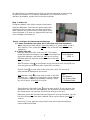
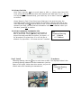
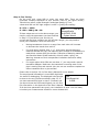
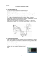
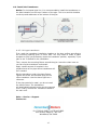
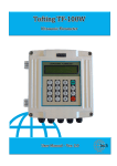
NCM-603 Hand Held Clamp-on Ultrasonic Transit Time Flowmeter Quick Start - Operation Manual Rev 10.01.08 This Quick Start is provided solely to help you get the flowmeter up and running as quickly as possible. For complete information on the flowmeter and its operation procedures, please refer to the User’s Manual. Step 1. Power On Charge the battery fully before using the instrument. Press the ON button. The meter will go through a selfchecking process to make sure everything is alright. After a second, the screen similar to the figure on the right will appear. If it does not, please write down the error message and contact us. Step 2. Configure the Measurement Settings 2.1. Enter transducer info (skip this if you have only one transducer pair) Change the Scale Factor: Press keys M45 (e.g., press MENU, 4 and 5 keys orderly.) Then, press the ENT key. Key in the new scale factor of the transducer 2.2. Enter pipe info M11 Pipe OD: press keys M11, and then ENT. The display Outer Diameter should be similar to the figure on the right. Now enter the pipe outer diameter, and press the ENT key to confirm. 4.500 in ENT and enter the pipe wall-thickness value. Press ENT =>_ again to confirm. Wall-Thickness: Press to scroll down to the next menu M12. Press ENT and enter the pipe wall-thickness value. Press ENT to conform. Pipe ID: Press to scroll down to the next menu, M13. The correct ID value should be displayed on the screen. Pipe Material: Press to scroll down to M14. Press ENT and then use to select the right item. If pipe material is not shown on the list (non-standard material), select any one of them. Press ENT to confirm. M14 Pipe Material =>0. Carbon Steel 1. Stainless Steel Sound Speed in Pipe Wall: Press to scroll down to M15. If you find your pipe material on the list in the previous step, the flowmeter should already know the sound speed. You can just skip this step and go to the next. Otherwise, press ENT and enter the sound speed of your pipe material. You can find this information in the User’s Manual. When you are done, press ENT to confirm. Pipe lining: If your pipe has lining inside, enter the lining information on menu windows M16-M18. 2 2.3. Enter fluid info Fluid Type: Use the key to scroll down to M20, or, simply press keys M20. Then, press ENT and select the item that matches your fluid type. If you do not find a match (non-standard fluid), just select any one of them. Press the ENT key to confirm. Sound Speed in Fluid: If you found your fluid type in the previous step, the flowmeter already has the sound speed info. Therefore, skip this step and go the next. Otherwise, press to scroll down to M21. Press ENT and key in the sound speed of your fluid. You can find this information in the User’s Manual. When you are done, press ENT to confirm. 2.4. Enter transducer installation info Mounting Method: Use the key to scroll down to M24 or press M24. Then Press ENT and select the proper item and press ENT to confirm. For pipes < 1” try W-method. For pipes from 2” to 12” use the V method. For pipe sizes > 12 inches use the Z method. Step 3. Install M24 Transducer Mounting =>0. V-Method 1.0 Z-Method Transducers Mounting Spacing: Use the key to scroll down to M25. The displayed value is the mounting spacing between the two transducers (see the figure on the right). Write down this number, as you will M25 need it later when installing the transducers. Transducer Spacing 3.80 in =>_ -3- Step 4. Fine Tuning On the main unit, press M90 to enter into menu M90. There are three important numbers displayed on this window (refer to the figure below): Transit-time ratio R, signal strength S and signal quality Q. Their values shall fall into the right ranges in order t o justify the reading: R: 97% ~ 103% S: 600 ~ 990 Q: 60 ~ 99. M90 100.39% StrengthQuality S=819,822 Q=88 System Normal If these values are not in the above ranges, you need to verify the parameters you have entered in Step 2. If you believe your entries are correct and the three numbers are still off their ranges, you may need to check your installation. Here are some tips: Moving transducers closer to or away from each other will increase or decrease the transit-time ratio R. For small pipes (smaller than 1 ½”), wrap some acoustic damping materials around the pipe, but leave an open window for transducers to make direct contact with pipe surface. Examples of damping material are GraceIce Water Shield materials, silicone rubber, epoxy, etc. Warning: be aware of their temperature limitations and other safety instructions. For copper pipes which ODs are less than 1”, you may need a special transducer adapter. Make sure the transducer mounting area on the pipe is coating-free and smooth. Also, do not use excessive couplant on either transducer face or pipe surface. Please refer to section 2.9.4 of the User’s Manual for more details. The sound speed information in menu M92 might also be useful for debugging. The displayed value should be close to the one you have entered in step 2.3. If you have entered fluid type in step 2.3 instead, and you do not know the fluid sound speed, you can find this information in the Appendix of the User’s Manual. M92 Fluid Sound Vel 0.0000 If all the three parameters are good, your installation is done. You are ready to look at your measurement results on menu window M00. 4 Appendix Transducer Installation Guide A.1. Find the mounting site (A) Pipe must be full of liquids at the measurement site. (B) No heavy corrosion of deposition inside of the pipe. (C) Must be a safe location. (D) The straight run of the pipe must not be shorter than 15D as a general guideline, where D is the pipe diameter. Insufficient straight pipe length will degrade the accuracy of the results. (E) The transducer mounting site should be 10D straight run upstream and 5D straight run downstream (see the following drawing.) (F) If there are flow disturbing parts such as pumps, valves, etc. on the upstream, the straight pipe length should be increased. The disturbance strength of those flow conducting parts will be (low to high): Single Bend -> Pipe Reduction / Enlargement -> Outflow Tee -> Same Plane Multiple Bends -> Inflow Tee -> Out of Plane Multiple Bends -> Valve -> Pump A.2. Prepare the Pipe Surface Clean the pipe surface where the transducers will be mounted. Remove rust and paint. Sand the surface if not smooth. Use wet cloth to wipe off the powder after sanding. Dry up the surface. A dry, clean surface will ensure a good acoustic bond between transducer and pipe. A.3. Prepare the Transducer Clean the transducer surface. Keep the surface dry. Put couplant on transducer surface as shown in the right figure. Do not put couplant more than necessary, especially for small pipe. 5 A.4. Install the Transducers Notice: For horizontal pipe line, it is recommended to install the transducers on the side instead of on the top or bottom of the pipe. This is to avoid air bubbles on the top and sediments on the bottom of the pipe. A.4.3. M1 type transducer: First, mark the transducer installation location on the pipe surface according to the mounting spacing given in menu M25. You may need to make a paper template to help you accurately locate the transducer position, especially if you plan to use Z-method for the installation. Then, connect the mounting fixture around the pipe. Leave the chain loose so you can slip the transducer underneath. Apply a small amount of couplant in the prepared area of the pipe where transducers will be in contact. Slip the transducer under the clamp fixture. Tighten the screw. Do the same thing for the other transducer. Use the above figure as a reference. If the pipe material is metal, you do not need the clamp fixture. The transducers will automatically attach to the pipe by magnetic force. Finally, connect the Transducer cables to the main unit. Sales – Service – Support Contact us.. Ph (770)516-3999, Fx (678)445-9993 501 Hickory Ridge Trl., Ste 110 Woodstock, GA 30188 -6- NCM-603 MENUE WINDOW DETAILS Menu No. Function M00 Display three positive negative net totalizers, signal strength, signal quality and working status M01 Display POS totalizer, flow rate, velocity, signal strength, signal quality and working status M02 Display NEG totalizer, flow rate, velocity, signal strength, signal quality and working status M03 Display NET totalizer, flow rate, velocity, signal strength, signal quality and working status M04 Display date and time, flow rate, signal strength, signal quality and working status M05 Display date and time, velocity, signal strength, signal quality and working status M06 Display the wave shape of the receiving signal M07 Display the battery terminal voltage and its estimated lasting time M08 Display the all the detailed working status, signal strength, signal quality M09 Display today's total flow, velocity, signal strength, signal quality and working status M10 Window for entering the outer perimeter of the pipe M11 M12 Window for entering the outer diameter of the pipe 0 to 6000mm is the allowed ranged of the value . Window for entering the pipe wall thickness M13 Window for entering the inner diameter of the pipe M14 Window for selecting pipe material. Standard pipe materials (that the user need not know the speed ) include:(0) carbon steel (1) stainless steel (2) cast iron (3) ductile iron (4) copper (5) PVC (6) aluminum (7) asbestos (8) fiberglass M15 Window for entering the pipe material speed only for non-standard pipe materials M16 Window for selecing the liner material, select none for pipes without any liner Standard liner materials that the user need not know the speed include: (1) Tar Epoxy (2) Rubber (3) Mortar (4) Polypropylene (5) Polystryol (6) Polystyrene (7) Polyester (8) Polyethylene (9) Ebonite (10) Teflon M17 Window for entering the liner material speed only for non-standard liner materials M18 Window for entering the liner thickness, if there is a liner M19 Window for entering the ABS thickness of the inside wall of the pipe. M20 Window for selecting fluid type for standard liquids that the user need not know the liquid speed include: (0) Water (1) Sea Water (2) Kerosene (3) Gasoline (4) Fuel Oil (5) Crude Oil (6) Propane at -45C (7) Butane at 0C (8) Other Liquids (9) Diesel Oil (10) Caster Oil (11) Peanut Oil (12) # 90 Gasoline (13) # 93 Gasoline (14) Alcohol (15) Hot water at 125C M21 Window for entering the fluid sonic velocity only for non-standard liquids M22 Window for entering the viscosity of the non-standard liquids M23 Window for selecting the proper transducers. There are 14 different types of transducers for selection. If the user-type-transducers are used, 4 user type wedge parameters, which will be prompted by the software, should be entered following. If the π type transducers are used, 3 π, type transducers and pipe parameters should be entered following. M24 Window for selecting the transducer mounting methods. Four methods can be selected: (0) V-method (1) Z-method (2) N-method (3) W-method M25 Display the transducer mounting spacing M26 Entry to store the parameter configuration into the internal NVRAM M27 Entry to load one set of saved parameters M28 Select YES or NO for the instrument to determine whether or not to hold (or to keep) the last correct value when poor signal condition occurs. Yes is the default setup. M29 Enter a value ranging from 000 to 999. 0 is the default value. M30 Window for selecting unit system. Default value is "Metric". The change from English to Metric of vice versa will not affect the unit for totalizers. M31 Window for selecting flow rate that will be used by the instrument afterward Flow rate can be in: 0. Cubic Meter short for (m3) 1. Liter (1) 2. USZ gallon (gal) 3. Imperial Gallon (igl) 4. Million USA gallon (mgl) 5. Cubic feet (cf) 6. USA liquid barrel (bal) 7. Imperial liquid barrel (ib) 8. Oil barrel (0b) The flow unit in terms of time can be per day, per hour, per minute or per second. So there are 36 different flow rate units in total for selection. M32 Window for selecting the totalizers"' working unit M33 Select totalizer multiplier. The multiplier ranges from 0.001 to 10000. M34 Turn on or turn off the NET totalizer M35 Turn on or turn off the POS totalizer M36 Turn on or turn off the NEG totalizer M37 (1) Totalizer Reset (2) Restore the instrument to the default parameters as the manufacturer did by pressing the dot key followed by the backspace key. Tale care or make note on the parameters before doing the restoration M38 Press-a-key-to-run or to stop totalizer for easier calibration M39 Operational interface language selection in Chinese and English. This selection makes it possible that more that 2 billion of people on the world can read the menu. M40 Flow rate damper for a stable valve. The input range is 0 to 999 seconds. 0 means there is no damping. Default value is 10 seconds. M41 Lower flow rate cut-off to avoid invalid accumulation. M42 Zero point setup under the condition when there is no liquid running inside the pipe M43 Clear the zero point by the user, and restore the zero point set by the manufacturer. M44 Set up a manual; flow bias. Generally this valve should be 0. M45 Scale factor for the instrument. The default value in "1". Keep this value as "1", when no user calibration has been made. M46 Network environmental Identification Number. Any interger can be entered except 13(0DH), carriage return), 10 (0 AH, line feeding), 42 (2,AH), 38, 65535. Every set of the instrument in a network environment should have a unique IDN. Please refer to the chapter for communication. M47 System locker to avoid modification of parameters M48 Not used M49 Communication Tester M50 "Option" selection for the built-in logger. It also functions as the switch of logger M51 Time setup for the data logger M52 (1) Data logging direction control. If ' To RS-232 ' is selected, all the data produced by the data logger will be transmitted out through the RS-232 interface. (2) If ' To buffer ' is selected, the data will be stored into the built-in logger memory. (3) Buffer transferring and buffer clearing M53 Logger buffer viewer. It functions as a file editor. Use Dot, backspace UP and DN keys to browse the buffer. If the logger is ON, the viewer will automatically refresh once new data are stored M54 M55 M56 M57 M58 M59 Not used Not used Not used Not used Not used Not used M60 99-year calendar. Press ENT for modification. Use the dot key to skip the digits that need no adjusting. M61 Display Version information and Electronic Serial Number (ESN) that are unique for each TDS-100 series flow meter. The users can employ the ESN for instrumentation management. M62 RS-232 setup. Baud rate can be 75 to 115200 bps M63 M64 M65 M66 Not used Not used Not used Not used M67 Input the frequency range for the frequency output. The biggest range is 0HZ-9999Hz. Default value is 1-1001 Hz M68 Enter a flow rate valve that corresponds to lower frequency M69 Enter a flow rate valve that corresponds to higher frequency M70 LCD display backlight control. The entered valve indicates how many seconds the backlight will be on with every key pressing. M71 LCD contrast control. The LCD will become darker when a small value is entered. M72 Working timer. It can be cleared by pressing ENT key, and the select YES. M73 Enter Lower Flow Rate value that will trigger the # 1 Alarm. There are two virtual alarms in the system. By "virtual" we mean that the user must redirect the output of the alarms by seting up the output hardware in M78 and M77. M74 Enter the higher flow rate value that will trigger the # 1 Alarm M75 Enter the lower flow rate value that will trigger the # 2 Alarm M76 Enter the higher flow rate value that will trigger the # 2 Alarm M77 Buzzer setup. If a proper input source is selected, the buzzer will beep when the trigger event occurs. M78 OCT (Open Collect Transistor Output) setup By selecting a proper input source, the OCT hardware will close when the trigger event occurs M79 Not used M80 Work as a keypad and display for another bandhold set by RS-232 connected with the handset. M81 Not used M82 Date totalizer M83 M84 M85 M86 M87 M88 M89 Not used Not used Not used Not used Not used Not used Not used M90 Display signal strength, signal quality, time ratio on the upper right corner. M91 Displays the Time Ratio between the Measured Total Transit Time and the Calculated time. It the pipe parameters are entered correctly and the transducers are properly installed, the ration valve should be in the range of 100+ 3%. Otherwise the entered parameters and the transducer installation should be checked. M92 Displays the estimated fluid sound velocity. If this value has an obvious difference with the actual fluid sound speed, pipe parameters entered and the transducer installation should be checked again. M93 Displays total transit time and delta time (transit time difference) M94 Displays the Reynolds number and the pipe factor used by the flow rate program M95 M96 Not used Not used M97 Command to record the pipe parameters entered by the user either to the built-in data logger or to RS-232C serial interface. M98 Command to record the pipe parameters entered by the user either to the built-in data logger or to RS-232C serial interface. M99 Command to copy the current display either to the built-in data logger or to RS-232C serial interface. M+0 Browse the 64 recorded instrument power-on and power-off data and time with the flow rate at the time of power on and off M+1 Displays the total working time of the instrument M+2 Displays the last power-off date and time M+3 Displays the last power-off flow rate M+4 Displays the times of instrument powered on (the instrument has been powered on) M+5 A scientific calculator for the convenience of field working. All the values are in single accuracy. The drawback is that the user can't operate it by direct key-pressing M+6 M+7 M+8 M+9 M+10 Not used Not used Not used Not used Entry to Firmware adjusting windows only for the manufacturer.