1
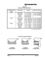
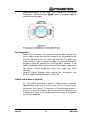
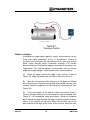
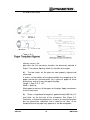
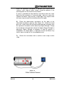
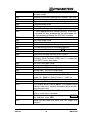
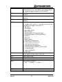
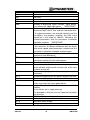
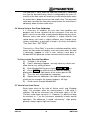
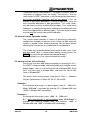
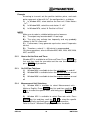
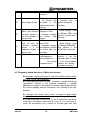
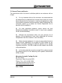
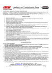
Series DMTF
Clamp-on & Insertion Transit
Time Ultrasonic Flow Meters
Operation & Maintenance Manual
REV 1/07
Table of Contents
Part 1 – Introduction ................................................................... 4
1.1
GENERAL ........................................................................................................................4
1.2
PRINCIPLE OF MEASUREMENT ..........................................................................................4
1.3
APPLICATIONS ................................................................................................................5
1.4
FEATURES ......................................................................................................................5
1.5
SPECIFICATIONS ..............................................................................................................6
1.6
MODEL SELECTION ..........................................................................................................7
Part 2 - Transducer Installation ................................................ 10
2.0
GENERAL ...................................................................................................................... 10
2.1
MOUNTING LOCATION .................................................................................................... 10
2.2
TRANSDUCER SPACING.................................................................................................. 12
2.3
TRANSDUCER MOUNTING ............................................................................................... 15
2.4
TRANSDUCER MOUNTING INSPECTION AND COUPLANT APPLICATION ................................ 21
2.4.1
Transducer Mounting Inspection ..........................................................................21
2.4.2
Couplant Application................................................................................................21
Part 3 - Instructions on Installation, ........................................ 22
Connection and Operation ....................................................... 22
3.1
TRANSMITTER INSTALLATION ......................................................................................... 22
3.2
TRANSDUCER INPUT CONNECTIONS ................................................................................ 23
3.3
TRANSMITTER POWER SUPPLY AND OUTPUT CONNECTIONS ............................................ 24
3.4
KEYPAD CONFIGURATION .............................................................................................. 26
3.4.1
Keypad functions ......................................................................................................26
3.4.2
Keypad Operation .....................................................................................................27
3.4.3
DMTF Window Descriptions ...................................................................................28
3.4.4
Pipe Parameter Entry Shortcuts............................................................................29
Part 4 - Windows Display Explanations................................... 31
Part 5 - How to Use Menu Functions ....................................... 38
5.1
HOW TO JUDGE WHETHER THE INSTRUMENT WORKS PROPERLY ...................................... 38
REV1/07
2
DMTF-B&C
5.2
HOW TO JUDGE THE LIQUID FLOWING DIRECTION ............................................................ 38
5.3
HOW TO RESET THE INSTRUMENT INTO DEFAULT SETTINGS ............................................. 38
5.4
HOW TO STABILISE THE FLOW ........................................................................................ 38
5.5
HOW TO USE THE ZERO-CUTOFF FUNCTION .................................................................... 38
5.6
HOW TO SETUP A ZERO FLOW CALIBRATION ................................................................... 39
5.7
HOW TO USE SCALE FACTOR ......................................................................................... 39
5.8
HOW TO USE THE OPERATION LOCKER ........................................................................... 40
5.9
HOW TO USE THE 4-20 MA OUTPUT ................................................................................ 40
5.10
HOW TO USE THE FLOW RATE FREQUENCY OUTPUT........................................................ 41
5.11
TOTALISER PULSE OUTPUT ............................................................................................ 41
5.12
HOW TO SET THE DATE AND TIMER ................................................................................. 42
5.13
ON/OFF FLOW TOTALISERS ........................................................................................... 42
5.14
MEASUREMENT UNIT SELECTIONS .................................................................................. 42
5.15
LCD BACKLIT OPTIONS ................................................................................................. 43
5.16
USE MENU WINDOWS FOR TRANSDUCER MOUNTING INSPECTION ..................................... 43
5.16.1
Signal Strength .......................................................................................................43
5.16.2
Signal Quality (Q Value)........................................................................................43
5.16.3
Total Time and Delta Time....................................................................................43
5.16.4
Transit Time Ratio ..................................................................................................44
5.16.5
Warnings ..................................................................................................................44
Part 6 - Troubleshooting and Frequently Asked Questions... 46
6.1
TROUBLESHOOTING ....................................................................................................... 46
6.2
FREQUENTLY ASKED QUESTIONS (FAQS) AND ANSWERS ................................................ 48
Part 7 – Limited Warranty and Service ..................................... 51
7.1
LIMITED WARRANTY AND DISCLAIMER ............................................................................ 51
7.2
GENERAL TERMS AND SERVICE ....................................................................................... 52
REV1/07
3
DMTF-B&C
Part 1 – Introduction
1.1 General
Engineers and technicians of fluid process management expect to
achieve flow measurement on the non-invasive pipeline in a
reliable and accurate method. DMTF series ultrasonic flow meter
was introduced to the world to satisfy this demand. It provides a
measuring system with high accuracy, versatility, reliability, and
ease of operation. Although the original design is primarily focused
on cleaner liquids, this kind of flow meter can also reliably measure
liquids containing moderate amounts of suspended solids or
aeration. DMTF series ultrasonic flow meter undertakes the longor short-term flow measurement surveys on full-pipe liquid
systems. It is an ideal to verify flow calibration for these
permanently mounted flow meters.
1.2 Principle of Measurement
The DMTF series ultrasonic flow meter is designed to measure the
fluid velocity of liquid within a closed pipe. The transducers are a
non-invasive, clamp-on type, which provides benefits of
non-fouling operation and ease of installation.
The DMTF series transit time flow meter utilises two transducers
that function as both ultrasonic transmitters and receivers. The
transducers are clamped on the outside of a closed pipe at a
specific distance from each other. The transducers can be
mounted in V-mode where the sound transverses the pipe twice, or
W-mode where the sound transverses the pipe four times, or in
Z-mode where the transducers are mounted on opposite sides of
the pipe and the sound crosses the pipe once. This selection of
mounting configurations depends on both pipe and liquid
characteristics. The flow meter operates by alternately transmitting
and receiving a frequency modulated burst of sound energy
between the two transducers and measuring the time interval that
it takes sound to travel between the two transducers. The
difference in the time interval is directly related to the velocity of
the liquid in the pipe, as shown in Figure 1.
Vf=Kdt/TL
Where:
Vf
REV1/07
Liquid velocity
4
DMTF-B&C
K
Constant
dt
Difference in time of flight through the following
TL
Average Transit Time
1.3 Applications
For Liquids
1.) Water, sewage (with low particle
content) and sea water
2.) Water supply and drainage water
3.) Process liquids; Liquors
4.) Milk, Yoghourt milk
5.) Gasoline, Kerosene and Diesel oil
For Industries
6.) Power plant
7.) The flow patrolling and examining
8.) Metallurgy, Laboratory
9.) Energy-conservation, economical water measurement
10.) Food and medicine
11.) Heat measures, Heat balance
12.) On-the-spot check-up, Pipeline leak detection & judgment
1.4 Features
Advanced Digital Signal Processing (DSP) technology and
the MultiBeamTM transducer technology
Digital Cross-correlation (DCC) technology
Non-invasive flow system allowing solids to pass through the
pipe within effect on meter. No Y-strainers or filtering devices
needed
No-contacting sensor design making no fouling and free
maintenance
Sensors suitable for different pipe materials with wide pipe
diameters
Easy and cost-effective installation by clamping transducers
on the outside of existing piping systems
User-friendly menu selections making DMTF easy
operations
User-configurable in English, Metric and other engineering
units worldwide
Event data logger available in searching the event of totaliser
flow
REV1/07
5
DMTF-B&C
Parallel operation of positive, negative and net flow totalisers
available
The totalise pulse output and frequency output available via
open collector
1.5 Specifications
Transmitter
Description
Principle of
Measurement
Power Requirements
Velocity
Outputs
Optional
Display
Units
Rate
Totaliser
Ambient Conditions
Enclosure
Accuracy Flow Rate
Repeatability
Responding Time
Communication
Interface
Security
Other Functions
REV1/07
Specifications
Principle of Transit Time, DSP technology and
MultiBeamTM Transducer Technology
115/230VAC 50/60Hz ± 15% @ 5VA max;
9-28VDC @ 2.5 VA max
0 ~ +12 m/s
All outputs are isolated form earth and system
grounds.
4-20 mA output:1000 ohm max, Accuracy: 0.1%
Pulse output:1~9999 Hz (from OCT) for Flow rate or
Total flow output
2 line×8character LCD back lit
English or Metric units
Rate and Velocity Display
Forward total; Reverse total; Net total (difference
between forward and reverse flow)
-40 to 131F [-40 to 55℃], 0-95% relative humidity,
non-condensing
NEMA 4X [IP65] Polycarbonate SS Brass and plated
steel
178H×146W×99D mm
±1.0% of reading at rates > 0.3 m/s uncalibrated;
±0.5% of reading at rates > 0.3 m/s for field
calibrated systems
±0.2% of reading
500 ms (2 set /seconds),
(Std) RS-232C, or (Opt) RS-485
Keypad lockout, Password or other access code
enable
1.) Automatic record incident and management of
flow measurement
2.) Remember the state of the flow meter
6
DMTF-B&C
3.) Diagnosis
Transducer
Description
Liquid Types
Liquid Temperature
Transducer Cable
Length
Pipe Size
Pipe Material
Specifications
Virtually most any liquid containing less than 5% total
suspended solids (TSS) or aeration
Magnetic force transducer, -40 to 180F [-40 to 82℃]
(Opt) -40 to 300 F [-40 to 150℃]
Shielded cable: (Opt) extensive length to 300 meters
(Std): 1 to 50 inches [25 to 1250 mm] pipe I.D.
(Opt): 50 to180 inches [1250- 4570 mm] pipe I.D
All kinds of steel and cast iron, and PVC
1.6 Model Selection
REV1/07
7
DMTF-B&C
DMTFTransit Time Ultrasonic Flow Meter
Transducer Mounting Method
B.) Clamp-on transducer
C.) Insertion transducer
Transmitter Enclosure
1.) Standard Enclosure
2.) Explosive Proof Enclosure, EEeX II
Input/Output 1
N.) None
1.) 4-20 mA
2.) Rate Pulse
3.) Totaliser Pulse
4.) RS232C
5.) RS485
6.) Heat Flow
Input/Output 2
Same as Input/Output 1
Transducer Type and Temperature
10.) S1 type clamp-on (pipe size 3/4 ~2 inches
-40 to 300F [-40 to 150℃]
11.) S1 type clamp-on (pipe size 3/4 ~2 inches)
Magnetic force transducer, -40 to 180F [-40 to 82℃]
20.) M1 type clamp-on (pipe size 1 ~ 50 inches)
-40 to 300F [-40 to 150℃]
21.) M1 type clamp-on (pipe size 1~50 inches)
Magnetic force transducer, -40 to 180F [-40 to 82℃]
30.) L1 type clamp-on (pipe size 50~180 inches)
Magnetic force transducer, -40 to 180F [-40 to 82℃]
Transducer Cable Length
020.) 20 feet [6.1 m]
050.) 50 feet [15 m]
100.) 100 feet [30 m]
Max. length: 990 feet [300 m] in 10 ft. [3 m] increments
REV1/07
8
DMTF-B&C
NOTE
1.)
One tube of silicone compound is included in a
transducer order. While mounting straps are excluded
2.)
REV1/07
Stainless steel mounting straps
A.)
Part Number (PN) is DM002-2007-001
B.)
36 inches [0.92 m] long and require some
overlap
C.)
Number of straps required (round up to the
next even number) =Pipe outside diameter [inches] x
6.2832 inches
9
DMTF-B&C
Part 2 - Transducer Installation
2.0 General
Utilised by the DMTF series flow meters, the transducers contain
piezoelectric crystals for transmitting and receiving ultrasound
signals through walls of liquid piping systems. The transducers are
relatively simple and straight-forward to install, but spacing and
alignment of the transducers is critical to the system's accuracy
and performance. Extra care needs to be taken to ensure that
these instructions are carefully executed.
Mounting of the clamp-on ultrasonic transit time transducers is
comprised of three steps:
1.) Selection of the optimum location on a piping system
2.) Entering the necessary parameters into the DMTF keypad
NOTE DMTF calculates proper transducer spacing according to
these entries in (M25)
3.) Pipe preparation and transducer mounting
2.1 Mounting Location
The first step in the installation process is to select an optimum
location for the flow measurement. For this to be done effectively, a
basic knowledge of the piping system and its plumbing is required.
An optimum location is defined as:
REV1/07
A piping system that is completely full of liquid when
measurements are being taken. The pipe may become
completely empty during a process cycle - which will result in
an error code being displayed on the flow meter while the pipe
is empty. Error codes will clear automatically once the pipe
refills with liquid. It is not recommended to mount the
transducers in an area where the pipe may become partially
filled. Partially filled pipes will cause erroneous and
unpredictable operation of the meter
A piping system that contains lengths of straight pipe
such as those described in Table 2.1. The optimum straight
pipe diameter recommendations apply to pipes in both
horizontal and vertical orientation. The straight runs in Table
2.1 apply to liquid velocities that are nominally 7 ft/s [2.2 m/s].
10
DMTF-B&C
As liquid velocity increases above this nominal rate, the
requirement for straight pipe increases proportionally
REV1/07
Mount the transducers in an area where they will not be
inadvertently bumped or disturbed during normal
operation
Avoid installations on downward flowing pipes unless
adequate downstream head pressure is present to overcome
cavitations in the pipe.
11
DMTF-B&C
2.2 Transducer Spacing
DMTF transducers are clamped on the outside of a closed pipe at
a specific distance from each other.
The transducers can be mounted in:
1.) V-mode where the sound transverses the pipe twice
2.) W-mode where the sound transverses the pipe four times
3.) Z-mode where the transducers are mounted on opposite
sides of the pipe and the sound crosses the pipe once only
For further details, refer to Table 2.2
REV1/07
12
DMTF-B&C
The appropriate mounting configuration is based on pipe and liquid
characteristics. Selection of the proper transducer mounting mode
is not entirely predictable and many times is an iterative process.
Table 2.2 contains recommended mounting configurations for
common applications. These recommended configurations may
need to be modified for specific applications if such things as
aeration, suspended solids or poor piping conditions are present.
W-mode provides the longest sound path length between the
transducers, but has the weakest signal strength, while Z-mode
provides the strongest signal strength, but has the shortest sound
path length.
On pipes smaller than 3 inches [75 mm], it is desirable to have a
longer sound path length, so that the difference in time interval can
be measured more accurately. It is very important to use of the
DMTF M90 and M91 in determining the optimum transducer
mounting.
REV1/07
13
DMTF-B&C
REV1/07
14
DMTF-B&C
The DMTF system calculates proper transducer spacing by
utilising piping and liquid information entered by the user.
The following information is required before programming the
instrument.
NOTE
Parameters relating to material sound speed, viscosity and specific
gravity are preprogrammed into the DMTF flow meter. These
parameter values only need to be modified if there is an unknown
pipe material or a particular liquid varying from the reference.
Refer to Part 3 of this manual for instructions on entering
configuration data into the DMTF flow meter via the meter keypad
See Table 2.2 Transducer mounting mode.
Pipe outside diameter (O.D.)
Pipe wall thickness
Pipe material
Pipe sound speed
Pipe relative roughness
Pipe liner thickness
Pipe liner material
Pipe liner sound speed
Fluid type
Fluid sound speed
Nominal values for these parameters are programmed within the
DMTF operating system. The nominal values may be used when
appear or may be modified if exact system values are known.
After entering the data listed above, the DMTF will calculate proper
transducer spacing for the particular data settings. This distance
will be in inches if the DMTF is configured in English units, or
millimeters if it is configured in Metric units.
2.3 Transducer Mounting
After selecting an optimum mounting location (Step 1) and properly
entered above parameters via the meter keypad (Step 2), it’s time
to turn to determine the proper transducer spacing (Step 3). The
transducers may now be mounted onto the pipe.
The transducers must be properly oriented on the pipe to provide
optimum reliability and performance. On horizontal pipes, the
transducers should be mounted 180 radial degrees from one
another and at least 45 degrees from the top-dead-center and
REV1/07
15
DMTF-B&C
bottom-dead-center of the pipe. See Figure 2.1 Transducer
Orientation – Horizontal Pipes. NOTE Figure 2.1 does not apply to
vertically oriented pipes.
Pipe Preparation
Before the transducers are mounted onto the pipe surface, two
areas slightly larger than the flat surface of the transducer heads
must be cleaned of all rust, scale and moisture. For pipes with
rough surfaces, such as ductile iron pipe, it is recommended that
the pipe surface be ground flat. Paint and other coatings, if not
flaked or bubbled, need not be removed. Plastic pipes typically do
not require surface preparation other than soap and water
cleaning.
Observe Signal Strength while placing the transducers into
position. Signal Strength displays in Menu 90.
V-Mode and W-Mode Installation
1.) For DMTF transducers, place a single bead of couplant,
approximately 0.05 inch [1.2 mm] thick, on the flat face of the
transducer. See Figure 2.2. Generally, a silicone-based grease is
used as an acoustic couplant, but any grease-like substance that
is rated not to “flow” at the temperature that the pipe may operate
at, will be acceptable.
REV1/07
16
DMTF-B&C
Figure 2.2
2.) Place the upstream transducer in position and secure with a
mounting strap. Straps should be placed in the arched groove on
the end of the transducer. A screw is provided to help hold the
transducer onto the strap. Verify that the transducer is true to the
pipe - adjust as necessary. Tighten the transducer strap securely
3.) Place the downstream transducer on the pipe at the
calculated transducer spacing. See Figure 2.3 Transducer Position.
Using firm hand pressure, slowly move the transducer both
towards and away from the upstream transducer while observing
Signal Strength. Clamp the transducer at the position where the
highest Signal Strength is observed. A Signal Strength (in M90)
between 60 and 95 is acceptable
4.) If after adjustment of the transducers, the Signal Strength (in
M90) does not rise to above 60, then an alternate transducer
mounting mode should be selected. If the mounting mode is
W-mode, then reconfigure the DMTF for V-mode, reset the DMTF,
move the downstream transducer to the new location and repeat
Step 3.
REV1/07
17
DMTF-B&C
Z-Mode Installation
Installation on larger pipes requires careful measurements to the
linear and radial placement of the L1 transducers. Failure to
properly orient and place the transducers on the pipe may lead to
weak signal strength and/or inaccurate readings. The section
below introduces a method for properly locating the transducers on
larger pipes. This method requires a roll of paper such as freezer
paper or wrapping paper, masking tape and a marking device:
1.) Wrap the paper around the pipe in the manner shown in
Figure 2.4. Align the paper ends to within 0.25 inches [6 mm]
2.) Mark the intersection of the two ends of the paper to indicate
the circumference. Remove the template and spread it out on a flat
surface. Fold the template in half, bisecting the circumference. See
Figure 2.5
3.) Crease the paper at the fold line. Mark the crease. Place a
mark on the pipe where one of the transducers will be located. See
Figure 2.1 for acceptable radial orientations. Wrap the template
back around the pipe, placing the beginning of the paper and one
corner in the location of the mark. Move to the other side of the
pipe and mark the pipe at the ends of the crease. Measure from
REV1/07
18
DMTF-B&C
the end of the crease
(directly across the
pipe from the first transducer location) the dimension derived in
Step 2, Transducer Spacing. Mark this location on the pipe
4.) The two marks on the pipe are now properly aligned and
measured.
If access to the bottom of the pipe prohibits the wrapping of the
paper around the circumference, cut a piece of paper to these
dimensions and lay it over the top of the pipe.
Length = Pipe O.D. X 1.57
Width = Spacing
Mark opposite corners of the paper on the pipe. Apply transducers
to these two marks
5.) Place a single bead of couplant, approximately 0.05 inch [1.2
mm] thick, on the flat face of the transducer. See Figure 2.2.
Generally, a silicone-based grease is used as an acoustic couplant,
but any grease-like substance that is rated to not “flow” at the
temperature that the pipe may operate at, will be acceptable.
REV1/07
19
DMTF-B&C
Place the upstream transducer in position and secure with a
stainless steel strap or other. Straps should be placed in the
arched groove on the end of the transducer.
A screw is provided to help hold the transducer onto the strap.
Verify that the transducer is true to the pipe - adjust as necessary.
Tighten transducer strap securely. Larger pipes may require more
than one strap to reach the circumference of the pipe
6.) Place the downstream transducer on the pipe at the
calculated transducer spacing. See Figure 2.6. Using firm hand
pressure, slowly move the transducer both towards and away from
the upstream transducer while observing Signal Strength. Clamp
the transducer at the position where the highest Signal Strength is
observed. Signal Strength of between 5 and 95 percent is
acceptable. On certain pipes, a slight twist to the transducer may
cause signal strength to rise to acceptable levels
7.) Secure the transducer with a stainless steel strap or other
strap
REV1/07
20
DMTF-B&C
2.4 Transducer Mounting Inspection and Couplant Application
2.4.1
Transducer Mounting Inspection
It is very important to use menu operations for TRANSDUCER
MOUNTING INSPECTION and Estimation
Refer to §5.16, using menu windows for Transducer Mounting
Inspection
2.4.2
Couplant Application
1.) It is also very important for couplant application. When
mounting the transducers, apply just enough pressure so that the
couplant can eliminate the gap between the pipe and transducer.
Commonly, Dow Corning 732 is used for permanent installation
while Dow Corning 111 is used for temporary installation
NOTE
When Dow Corning 732 is used, ensure:
A.) No relative movement between the transducers
B.) The pipe takes place during the setting time,and
C.) Do not apply instrument power for at least 24 hours
Dow Corning 111 is also used for permanent installations (avoid
rain or water), setting time is not necessary. Dow Corning 112 is
suitable for high temperature application
2.) Transducers for High Temperature
Mounting of high temperature transducers is similar to DMTF
standard transducers. High temperature installations require
acoustic couplant Dow Corning 112 that is rated not to flow at the
temperature that will be present on the pipe surface
REV1/07
21
DMTF-B&C
Part 3 - Instructions on Installation,
Connection and Operation
3.1 Transmitter Installation
After unpacking, it is recommended to save the shipping
carton and packing materials in case the instrument is stored
or re-shipped. Inspect the equipment and carton for damage.
If there is evidence of shipping damage, notify the carrier
immediately.
The enclosure should be mounted in an area that is convenient for
servicing, calibration or for observation of the LCD readout (if
equipped):
1.) Locate the transmitter within the length of transducer cable
that is supplied with the DMTF system. If not possible, it is
recommended that the cable be replaced with the one having
proper length. Transducer cable that is up to 990 feet [300 meters]
may be accommodated
2.)
Mount the DMTF transmitter in a location where is:
Little vibration existing
Protected from falling corrosive fluids
Within ambient temperature limits: -40 to 185°F [-40 to
85°C]
Avoiding direct sunlight: Direct sunlight may increase
transmitter temperature to above the maximum limit
3.) Mounting: Refer to Figure 3.1 for enclosure and mounting
dimension details. Ensure that enough room is available to allow
for door swing, maintenance and conduit entrances. Secure the
enclosure to a flat surface with four appropriate fasteners
4.) Conduit holes: Conduit hubs need to be used where cables
enter the enclosure. Holes not used for cable entry should be
sealed with plugs
5.) If additional holes are required, drill the appropriate size hole
in the enclosure’s bottom. Take extra care not to drill a bit into the
wiring terminals or electronic circuit boards
REV1/07
22
DMTF-B&C
NOTE
Use NEMA 4 [IP65] rated fittings/plugs to maintain the water tight
integrity of the enclosure. Generally, the left conduit hole (viewed
from front) is used for the power supply, the center conduit hole is
used for transducer Inputs, and the right hole is used for Output
wirings
3.2 Transducer Input Connections
To access terminal strips for transducer connections:
1.) Loosen two screws on the enclosure door first and then open
the door
2.) Guide the transducer terminations through the transmitter
conduit hole located in the bottom-center of the enclosure
3.) The terminals in the transmitter are a pluggable type: which
can be removed wirings and then plugged back in. Connect the
REV1/07
23
DMTF-B&C
appropriate wires to the corresponding screw terminals in the
transmitter
4.) Observe UP/DN Str. Xdcr orientation: If flow rate displays
negative, exchange the UP/ DOWN transducer wirings
NOTE
A.) The transducer cable carries low level high frequency signals.
In general, it is not recommended to arrange other cable with the
transducer cable
B.) If additional cable is required, contact the Dynameters
factory to make an exchange for the transducer cable with
appropriate length
C.) Transducer cable is available to extend to 990 feet [300
meters]
3.3 Transmitter Power Supply and Output Connections
1.) Power Supply Connection
AC Power Connection: Connect line power input wires (115 / 230
VAC, 50 / 60 Hz ± 15% @ 5 VA max) to the 220VAC Screw
Terminals: AC, GND in the transmitter. See Figure 3.2. The ground
terminal grounds the instrument, which is mandatory for safe
operation.
DC Power Connection: Connect DC power input wires (9 to 28
VDC @ 2.5 VA max) to the 24VDC Screw Terminals: + and – in the
transmitter.
NOTE
This instrument requires clean electrical line power. Do not operate
this unit on circuits with noisy components (for example,
fluorescent lights, relays, compressors, or variable frequency
drives). It is recommended not to run line power with other signal
wires within the same wiring tray or conduit.
REV1/07
24
DMTF-B&C
2.) 4-20 mA Output Connection
Connect 4-20mA output wires to the 4–20 mA Screw Terminals: +,
- in the transmitter. Please note that the 4-20 mA output does not
require power from an external DC power source
3.) Pulse Frequency Output Connection
Connect Pulse Frequency Output wires to the “Pulse F. Out”
Terminals: +, - in the transmitter. The pulse output is utilised of
transmit information to external counters and PID systems via a
frequency output that is proportional to flow rate or total flow (can
be configured in the Menu) of the system. The frequency output
ranges from 0 –1,000 Hz
NOTE
A.) This type of pulse output is an open-collector transistor (OCT)
type that does not have a internal power source as its output,
requiring an external DC power source and pull-up resistor
B.) Resistor selection is based on the input impedance of the
receiving device. Select a resistor that is a maximum of 10% of the
input impedance of the receiving device, but do not exceed 10k
Ohms
C.) See Figure 3.3: The voltage value of External DC power
Supply depends on Pulse Output receiver. Normally, 1 - 24V is
allowable
REV1/07
25
DMTF-B&C
3.4 Keypad Configuration
3.4.1
Keypad functions
After installation of transducers and connection of appropriate
power supply to DMTF, keypad configuration of the instrument can
be undertaken. Generally, there is no any display of error
messages. The flow meter can go to the most commonly used
Menu Window Number 01 (M01), which displays the Velocity, Flow
Rate, Positive Totaliser, Signal Strength and Signal Quality
according to the pipe parameters entering by the user or by the
initial program.
The DMTF contains a 16-key tactile keypad, allowing the user to
view and change parameter configurations, which is as shown
below (Figure 3.4).
Figure 3.4
REV1/07
26
DMTF-B&C
Follow these guidelines when using DMTF keypad:
Keys 0 ~ 9 and ● used to input numbers and decimal
Key F1 used to backspace or delete characters to the left
The arrow keys ∧ and ∨ used to return to the last menu or to
open the next menu, scrolling through menu for parameter
configurations; also to act as “+” and “-” functions when entering
numbers
Key MENU is used to select a menu. To enter a desired window,
press MENU key first, and then followed by input two-digit window
address code. For instance, to input a pipe wall thickness, press
MENU key first and then press 1 and 2 keys. Window M12 is the
menu to display the pipe wall thickness, and 12 is the Window
address code or the serial number
3.4.2
Keypad Operation
With all of the parameters entered, the instrument setup and
measurement displays are subdivided or consolidated into more
than 100 independent windows. The user can view the window
menu, input parameters, modify settings or display measurement
results. These windows are arranged by 2-digit serial numbers
(including ∧ symbol) from 00 to 99, then to ∧ 0 , ∧ 1 , and so
on. Every window serial number, or so-called window address
code, has a defined meaning. For instance, Window No.11 (M11)
indicates the input for the pipe outside diameter, while Window
M25 indicates the mounting space between the transducers. For
details about window menus, please refer to Part 4 – Windows
Display Explanations
A.) The keypad shortcut to visit a specific window is to press the
MENU key at any time, and then followed by input 2-digit window
address code. For instance, to input or check the pipe outside
diameter, just press the MENU, 1 and 1 keys for entering window
M11
B.) Another method to visit a specific window is to press∧
∧, ∨
and ENTER keys to scroll the menu. For instance, if the current
window is M66, press ∧ key to enter Window M65, press the ∧
again to enter Window M64; then, press the ∨ key to back
Window M65, and press the ∨ key again to enter Window M66
REV1/07
27
DMTF-B&C
Example 1
To enter a pipe outside diameter of 216.2, the procedure is as
follows:
Press MENU, 1 and 1 keys to enter Window M11 (The displayed
value currently is a previous value,). Please refer to the left Figure
below. Now press ENTER key. The symbol “﹥
﹥” and the flashing
cursor are displayed at the left end of the second line on the
Screen. Please refer to the right Figure below. The new value can
be entered by pressing 2 , 1 , 6 , ● , 2 keys and
finally pressing ENTER key to confirm.
Input pipe outside diameter M11
312 mm (previous value)
Input pipe outside diameter M11
﹥ (once enter is pressed, input new value here
Example 2
If the pipe material is “Stainless Steel”, press keys MENU 1 4
to enter Window M14 first. Then press ENTER key to modify the
options. Now, select the “1. Stainless Steel” option by pressing∧
∧
and ∨ keys, and finally press ENTER key to confirm the selection.
It is possible to press 1 key to change the selection and wait until
“1. Stainless Steel” is displayed on the second line of the screen.
Then press the ENTER key to confirm.
Generally, press ENTER key first if operator wants to enter
“modify” condition. If the “modify” is still not possible even after
pressing the ENTER key, it means that system is locked by a
password. To unlock it, select “Unlock” in Window M47 and enter
the original password. The keypad will not respond if the keypad is
locked. It can only be unlocked by the entering original password.
Select keypad lock functions in Window M48. Please contact the
factory for password issues if necessary.
3.4.3
DMTF Window Descriptions
The DMTF has a unique feature of windows processing for all
operations.
These windows are assigned as follows:
M00~
~ M09 windows for displaying flow rate, velocity, positive
total, negative total, net total, date & time, present operation and
flow results today
REV1/07
28
DMTF-B&C
M10~
~M29 windows for initial parameter settings: To setup pipe
outside diameter, pipe wall thickness, fluid type, transducer type,
transducer mounting and spacing
M30~
~M38 windows for flow units setup options: To select the
flow unit, totaliser unit, measurement unit, turn totalisers on/off and
reset totalisers
M40~
~ M49 windows for setup options: To setup scale factor,
network IDN (Window M46), system lock (Window M47) and
keypad lock code (Window M48)
M50~
~ M89 windows for Input and output setup: To configure
relay output setup, 4-20mA outputs, flow batch controller, LCD
backlit option, date and time, low/high output frequency, alarm
output, date totaliser
M90~
~ M94 windows for diagnosis: Signal strength and signal
quality (Window M90), TOM/TOS*100 (Window M91), flow sound
velocity (Window M92), total time and delta time (Window M93),
Reynolds number and factor (Window M94)
M∧0~M∧8 appendix: Power on/off time, total working hours,
on/off times and hardware adjustment, which is used by the
manufacturer only
For further information, refer to Part 4 – Windows Display
Explanations. When having questions, please follow the
step-by-step instructions in the following section (Refer to §3.4.4
Pipe Parameter Entry Shortcuts).
3.4.4
REV1/07
Pipe Parameter Entry Shortcuts
The following parameters need to be entered for a normal
measurement:
1.) Pipe outside diameter
2.) Pipe wall thickness
3.) Pipe material
4.) Liner material parameters (including thickness and sound
speed, if needed)
5.) Fluid type
6.) Transducer type (The transmitter is connected with various
29
DMTF-B&C
transducer types: For DMTFB, the transducer can be a S1, M1, or
L1 type. While for DMTFC, the transducer is the Plug-in type - B45
only.)
7.) Transducer mounting methods, (Refer to Part 2, W-, V-, and
Z- mountings)
According to the above-stated order, to setup these parameters by
the following keypad shortcuts:
1.) Press MENU 1 and 1 keys to enter Windows M11 first, and
then enter the pipe outside diameter value, and finally press the
ENTER key to confirm
2.) Press the ∨ key to enter Window M12 first, and then enter
pipe wall thickness value, and finally press ENTER key to confirm
3.) Press the ∨ key to enter Window M14 first, press the
ENTER key to modify, move the ∧ or ∨ key to select a right pipe
material, and press the ENTER key to confirm
4.) Press the∨
∨ key to enter Window M16 first, press the
ENTER key to modify, move the ∧ or ∨ key to select a right liner
material, and press the ENTER key to confirm
5.) Press the ∨key to enter Window M20 first, press the ENTER
key to modify, move the ∧ or ∨ key to select the fluid type, press
the ENTER key to confirm
6.) Press the∨
∨ key to enter Window M23 first, press the
ENTER key to modify, move the ∧ or ∨ key to select a right
transducer type, and press the ENTER key to confirm
7.) Press the ∨ key to enter Window M24 first, press the
ENTER key to modify, move the ∧ or ∨ key to select a right
transducer-mounting method, and press the ENTER key to
confirm
8.) Press the∨
∨ key to enter Window M25, accurately install the
transducers according to the displayed transducer mounting
spacing and the selected mounting method Refer to Part 2 –
Installation of the Transducers
9.) Press the MENU 0
display measurement result
REV1/07
1 keys to enter Window M01 to
30
DMTF-B&C
Part 4 - Windows Display Explanations
Windows Display Explanations
Menu window No.
Functions
M00
Display flow rate / net totaliser
M01
Display flow rate / velocity
M02
Display flow rate / positive flow
M03
Display flow rate / negative flow
M04
Display date/flow rate
M05
Display heat flow rate
M06
Display analog signals input
M07
Display analog signals input
M08
Display system error codes
M09
Display Net flow today
M10
Window for entering the pipe outer perimeter
(commonly not used if input outer diameter below)
M11
Window for entering the pipe outer diameter,
0 to 6000 mm is the allowable range.
M12
Window for entering the pipe wall thickness
M13
Window for entering the pipe inner diameter of the
pipe
M14
Window for selecting the pipe material
Standard pipe materials (that have been programmed
into the flow meter and users ignore to know the
sound velocity in the material), including:
0.) Carbon steel 1.) Stainless steel 2.) Cast iron
3.) Ductile iron 4.) Copper 5.) PVC 6.) Aluminum
7.) Asbestos 8.) Fiberglass
9.) Other
M15
Window for entering the pipe material sound velocity
only for non-standard pipe materials if selecting
“Other” in M14
M16
Window for selecting the liner material, select none for
pipes without any liner. Standard liner materials (that
the user does not need to know the sonic velocity in
the material), including:
0.) None, No liner
1.) Tar Epoxy
2.) Rubber
3.) Mortar 4.) Polypropylene
5.) Polystryol
6.) Polystyrene
7.) Polyester 8.) Polyethylene
9.) Ebonite 10.) Teflon 11.) Other
M17
Window for entering the liner material sound velocity
REV1/07
31
DMTF-B&C
M18
M19
M20
M21
M22
M23
M24
M25
M26
M27
M28
M29
M30
M31
REV1/07
only for non-standard liner materials if selecting
“Other” in M16
Window for entering the liner thickness, if there is a
liner
Window for entering the roughness of the inside wall
of the pipe
Window for selecting fluid type
For standard liquids (that the user does not need to
know the liquid sonic velocity), including:
0.) Water 1.) Sea Water 2.) Kerosene
3.) Petrol
4.) Fuel oil 5.) Crude Oil
6.) Propane at -45℃ 7.) Butane at 0℃
8.) Other 9.) Diesel Oil 10.) Caster Oil
11.) Peanut Oil 12.) Petrol #90
13.) Petrol #93
14.) Alcohol 15.) Hot water at 125 ℃
Window for entering the fluid sound velocity only for
non-standard liquids if selecting “Other” in M20
Window for entering the viscosity of the non-standard
liquids if selecting “Other” in M20
Window for selecting the proper transducer type
There are different types of transducers for selection:
DMTF-B: selecting S1, M1, or L1 type
DMTF-C: selecting Plug-in type B45 only
Window for selecting the transducer mounting
methods. Four methods can be selected:
0.) V-method 1.) Z-method
2.) N-method 3.) W-method
Window for displaying the transducer mounting
spacing
Entry to save the parameter setups into the internal
Display liquid cross section area
Select YES or NO for the instrument to determine
whether or not to hold (or to keep) the last correct
value when poor signal condition occurs. YES is the
default setup
Setting state of empty pipe
Window for selecting unit system. Default value is
“Metric”. The change from English to Metric or vice
versa will not affect the unit for totalisers
Window for selecting flow rate that will be used by the
instrument afterward
32
DMTF-B&C
M32
M33
M34
M35
M36
M37
Flow rate can be in unit of
0.) Cubic meter
(m3)
1.) Liter
(l)
2.) U.S. gallon
(gal)
3.) Imperial Gallon
(igl)
4.) Million USA gallon
(mgl)
5.) Cubic feet
(cf)
6.) USA liquid barrel
(bal)
7.) Imperial liquid barrel
(ib)
8.) Oil barrel
(ob)
The flow unit in terms of time can be per day, per hour,
per minute or per second. So there are 36 different
flow rate units totally for selection
Window for selecting the totalisers’ working unit
default is m3
Select totaliser multiplier
The multiplier ranges from 0.001 to 10000 Default
value is ×1
Turn on or turn off the NET totaliser
Turn on or turn off the POS totaliser
Turn on or turn off the NEG totaliser
1.) Totaliser reset selection
2.) Restore the instrument to the default parameters
by pressing ● and F1 keys
M38
M39
M40
M41
M42
M43
M44
M45
REV1/07
Take care to make a record on the original settings for
parameters before doing the restoration
Manual Totaliser On/Off setup
Operational interface language selection between
Chinese and English
Flow rate damping setup for a stable value. The input
range is 0 to 999 seconds
“0” means there is no damping. Default value is 10
seconds
Lower flow rate cut-off to avoid invalid accumulation
Zero point setup under the condition when there is no
liquid running inside the pipe
Clear the zero point set by the user, and restore the
zero point set by the manufacturer
Set up a manual flow bias. Generally this value is 0
Scale factor setup for the instrument. The default
33
DMTF-B&C
M46
M47
M48
M49
M50
M51
M52
M53
M54
M55
M56
M57
M58
M59
M60
M61
M62
M63
M64
M65
M66
M67
M68
M69
M70
M71
M72
M73
REV1/07
value is 1. Keep this value as “1”, when no calibration
has been made
Network environment Identification Number. Not used
System locker to avoid modification of parameters
Keypad locker (Password setup via keypad)
Communication tester
Data logger option
Logger time setup for the data logger
1.) Data logging direction control. printing “To RS-232”
is selected, all data produced by the data logger will
be transmitted out through the RS-232C interface
Analog Input - AI5
AI5 value range setup
Mode of current output
The flow rate value at 4 mA output opposite
The flow rate value at 20 mA output opposite
Current loop (CL) checkup, press ENT when ready
CL output
Enactment the date and time of the system
Window for displaying Version information and
Electronic Serial Number (ESN) that is a unique for
each DMTF series flow meter
RS-232C serial port setup
Analog input - AI1 value range setup
Analog input - AI2 value range setup
Analog input - AI3 value range setup
Analog input - AI4 value range setup
Setup the frequency output range (FO). The biggest
range is 0 - 9999 Hz. Default value is 1-1001 Hz
Setup a low FO flow rate value
Setup a high FO flow rate value
LCD display backlit control option The entered value
indicates how many seconds the backlit will be on with
every key pressing
LCD contrast control. The LCD will become darker
when a small value is entered
Working timer. It can be cleared by pressing ENTER
key, and then select YES
Setup the low flow rate value that will trigger the
Alarm #1
34
DMTF-B&C
M74
M75
M76
M77
M78
M79
M80
M81
M82
M83
M84
REV1/07
There are two virtual alarms in the system. By “virtual”
means that the user must redirect the output of alarms
by setup the output hardware in M78 and M77
Setup the high flow rate value that will trigger the
Alarm #1
Setup the low flow rate value that will trigger the
Alarm #2
setup the high flow rate value that will trigger the
Alarm #2
Buzzer setup
If a proper input source is selected, the buzzer will
beep when the trigger event occurs
0.) No signal
1.) Poor Signal
2.) Not ready (No*R)
3.) Reverse flow
4.) Analog output (AO) overflow100%
5.) Frequency output (FO) overflow120%
6.) Alarm #1
7.) Alarm #2
8.) Batch control
9.) POS totaliser input pulse
10.) NEG totaliser input pulse
11.) Net totaliser input pulse
12.) Energy totaliser input pulse
13.) Communication ON/OFF via RS-232C
14.) Fluid changed
15.) Key stroking ON
16.) Not used
OCT output setup
(Pulse output for flow rate or total flow)
Relay output setup
Flow batch control in
Flow batch controller
Date totaliser selection:
0.) Day 1.) Month 2.) Year
Auto gain the totaliser flow if system power off
Not used
35
DMTF-B&C
M85
M86
M87
M88
M89
M90
M91
M92
M93
M94
M95
M∧0
M∧1
M∧2
M∧3
M∧4
M∧5
M∧6
M∧7
M∧8
M∧9
REV1/07
Not used
Not used
Not used
Not used
Not used
Window of displaying signal strength, signal quality,
time ratio on the upper right corner *IMPORTANT!
Window of displaying the Time Ratio between the
Measured Total Transit Time and the Calculated time.
If the pipe parameters are entered correctly and the
transducers are properly installed, the ratio value
should be in the range of 100±3%. Otherwise the
entered parameters and the transducer installation
should be checked
*IMPORTANT!
Window of displaying the estimated fluid sound speed
If this value has an obvious difference with the actual
fluid sound speed, pipe parameters entered and the
transducer installation should be checked again
Window of displaying total transit time and delta
time(transit time difference)
Window of displaying the Reynolds number and the
pipe factor used by the flow rate program
Open the circle display function
Browse the 64 recorded instrument power-on and
power-off date and time with the flow rate at the time
of power on and off
Window of displaying the total working time of the
instrument
Window of displaying the last power-off date and time
Window of displaying the last power-off flow rate
Window of displaying the times of instrument powered
on(the instrument has been powered on)
A scientific calculator for the convenience of field
working.
All the values are in single accuracy
The drawback is that the user can’t operate it by direct
key-pressing
Enter the liquid sound speed change
Protocol selection
Ultrasonic Wave Shape
Energy rate setup
36
DMTF-B&C
NOTE
Some contents in the windows are not listed or displayed in new
software version. However this situation does not affect users to
operate DMTF series. By pressing ∧ or ∨ to scroll the menu
windows, users can easily view or change some parameter if
necessary.
REV1/07
37
DMTF-B&C
Part 5 - How to Use Menu Functions
5.1 How to Judge Whether the Instrument Works Properly
In general,
when “R” is displayed in the lowest right corner of LCD
screen, the instrument is working properly.
If a “H” is flashing on that place, it could be a poor signal
received.
If an “I” is displayed, it means no signal detected.
If a “J” is displayed, it means that the hardware could be out
of order.
Refer to Part 6 for diagnosis.
5.2 How to Judge the Liquid Flowing Direction
Make sure that the instrument works properly
Check the flow rate:
1.) If the displayed value is “+” will it is “positive”; if the displayed
value is “-”, it is “negative”
2.) If the displayed value is “positive”, the direction of the flow
will be from the Upstream transducer to the Downstream
transducer; if the displayed value is “negative”, the direction of the
flow will be from the Downstream transducer to the Upstream
transducer
5.3 How to Reset the Instrument into Default Settings
Enter M37 when displaying the “selection” message. Press the dot
key ●first and the message “Master Erase” will display, then press
the backspace key F1. The master erase step will erase all the
parameters entered by the user and setup the instrument in default
status.
5.4 How to Stabilise the Flow
The damping acts as a filter for a stable reading. If “0” is entered in
window M40, it means there is no damping. A bigger number
brings more stable effect. But bigger damping numbers prevent the
instrument from acting quickly. Numbers: 0 to 10 are commonly
used for the damping setup.
5.5 How to Use the Zero-Cutoff Function
The displayed value in window M41 is called the low-cutoff value.
REV1/07
38
DMTF-B&C
The flow rate is “Zero” when the flow rate value that is absolutely
less than the low-cutoff value, which is configured by the user. It is
useful that the flow meter will avoid any invalid accumulation when
the actual flow is below the zero or low-cutoff value. The low-cutoff
value does not affect the flow measurement when the actual flow is
absolutely above the low-cutoff value.
5.6 How to Setup a Zero Flow Calibration
It is necessary to establish the true zero flow condition and
program such a zero set point into the instrument. If the zero set
point is not at true zero flow, a measurement difference may occur.
Because every flow meter installation is slightly different and
sound waves can travel in slightly different ways through these
various installations, a provision is made in this entry to establish
“True Zero” flow – SET ZERO.
There exists a “Zero Point” in a certain installation condition, which
means the flow meter will display a non-zero value when the flow
is absolutely stopped. In such a case, setting a zero point in
Window M42 will generate a more accurate measurement result.
To Successfully Zero the Flow Meter
1.) The pipe is full of liquid
2.) Flow is absolutely stopped - securely close any valves and
allow time for any settling to occur
3.) Enter Window M42 by pressing the MENU 4 2 keys
4.) Press ENTER key and wait until the counter readings
displayed in the lower right corner of the screen goes to “00”
5.) Thus, the zero set procedure is complete
6.) Repeat zero set calibration if the flow still needs to be
minimised, for example, the velocity reading is still high
7.) Check results through Window M01
5.7 How to Use Scale Factor
Scale factor refers to the ratio of “Actual value” and “Reading
value”. For example, when the measurement is 2.00, while it
indicates 1.98 on the instrument, the scale factor value is 2/1.98.
The best scale factor constant is 1. However, it is difficult to keep
the constant as “1” on the instrument, especially in batch control
operations. The difference is called “consistency”. High quality
products always require high consistency.
REV1/07
39
DMTF-B&C
The default value of scale factor is “1” for each instrument, which is
setup prior to shipment from the factory. The reason is that the
scale factors in DMTF flow meter is only limited by two parameters:
the crystal oscillation frequency and the transducer. It has no
relation to any circuit parameters. During an operation, there still
exists possible difference in pipe parameters. The “scale factor”
may be necessary when used on different pipes. Thus, scale factor
calibration is specially designed for calibrating the differences that
result from application on different pipes. The scale factor entered
must be one that results from actual calibration.
5.8 How to Use the Operation Locker
The system locker provides a means of preventing inadvertent
configuration changes or totaliser resets. Using the M48 when the
system is locked, menu window browsing can be done without
affecting any change, but any modifications are prohibited.
The system can be locked without a password or with a one 1 to 8
digit password. With a no-password locking, directly press the
ENTER key when the password input prompt displays.
If the password is an issue, please contact the factory.
5.9 How to Use the 4-20 mA Output
Possessing a current loop output exceeding an accuracy of 0.1%,
the DMTF is programmable and configurable with multiple current
output modes, such as 4-20 mA or 0-20 mA in Window M55. Enter
the 4 mA flow value in Window M56, and enter the 20 mA flow
value in Window M57.
For details about analog output setup,refer to Part 4 – Windows
Display Explanations on Menu 55, 56, 57, 58 and 59.
Example 1
Assuming the flow range in a specific pipe is from 0 ~ 1000 m3/h,
Mode “4-20 mA” is available by entering “0” in Window M56 and
“1000” in Window M57 accordingly
Example 2
Assuming the flow range is from -1000 ~ 0 ~ 2000 m3/h
A.) When flow direction is not considered, Mode “20-4-20 mA” is
available by selecting Window M55, and entering “-1000” in
Window M56 and “2000” in Window M57 accordingly
REV1/07
40
DMTF-B&C
B.) When flow direction is considered, Mode “0-4-20 mA” is
available. When the flow direction displays as negative, the current
output is in range of 0-4 mA, whereas the 4-20 mA is for the
positive direction. The output mode options are displayed in
Window M55. Enter “-1000” in Window M56 and “2000” in Window
M57
Calibrating and testing the current loop is performed in Window
M58.
Complete the steps as follows: Press Menu, 5 , 8 , ENTER , move
∧ or ∨ to display “0 mA”, “4 mA”, “8 mA”, “16 mA”, “20 mA”
readings, connect an ammeter to test the current loop output and
calculate the difference. Calibrate it if the difference is within
tolerance.
Check the present current loop output in Window M59 as it
changes along with change in flow.
5.10
How to Use the Flow Rate Frequency Output
DMTF provides a frequency output transmitter function. The high
or low frequency output displayed indicates the high or low flow
rate reading. The user can reset the frequency output and flow rate
if required For example, if a pipe flow range is from 0 ~ 2000 m3/h,
the relative frequency output configuration is 10~1000Hz, and
The configuration procedure is as follows:
1.) In Window M68 (low limit frequency output flow value), input
0
2.) In Window M69 (high limit frequency output flow value), input
2000
3.) In Window M67 (Select frequency range), Press ENTER,
input Low FO frequency 10, Press ∨ , input 1000
NOTE
There is no output circuit specially assigned to frequency output. It
only can be transmitted through OCT output. Select Item 13 (“13.
FO”) in Window M78 for details.
5.11
REV1/07
Totaliser Pulse Output
Wiring terminals are on Pulse F. Out, same as the Flow rate
Frequency Output.
41
DMTF-B&C
Example
Assuming to transmit out the positive totaliser pulse, and each
pulse represents a flow of 0.1m3, the configuration is as follows:
1.) In Window M32, select totaliser the flow unit “Cubic Meters
(m3)”
2.) In Window M33, select the scale factor “2. ×0.1”
3.) In Window M78, select “9. Positive int Pulse”
NOTE
Make sure to select a suitable totaliser pulse, because:
A.) The output may be extended if it is too large
B.) The relay may activate too frequently and may probably
shorten its life if it is too small
C.) Furthermore, it may generate a pulse loss error if it operates
too fast
D.) Therefore, a rate of 1 ~ 60 /minute is recommended
For these operations, refer to Window M32, M33, M34, M35, M36,
M37, and M78.
5.12
How to Set the Date and Timer
Window M72 is available to set Date and Timer. Press ENTER key
first and then input the new data and the new timer and finally
press ENTER key to confirm
5.13
On/Off Flow Totalisers
1.) Window M34 is available to turn the net totaliser on and off
2.) Window M35 is available to turn the positive totaliser on and
off
3.) Window M36 is available to turn the negative totaliser on and
off
5.14
Measurement Unit Selections
1.) Window M30 is available to select Measurement units Metric or English. Press ENTER key first and then scroll the ∧ or
∨ key to select the specific units, and finally press ENTER key to
confirm
2.) Window M31 is available to select Flow rate units. Press
ENTER key first and then scroll the ∧ or ∨ to select the specific
units, and finally and finally press ENTER key to confirm
Refer to Part 4 - Windows Display Explanations for details.
REV1/07
42
DMTF-B&C
5.15
LCD Backlit Options
Adjustment of the backlight is in window M70. Press MENU, 7 , 0
to enter M70 then press ENTER for modification, using ∧ or ∨ to
scroll the menu until select the backlit options, and finally press
ENTER key to confirm the change
5.16
Use Menu Windows for Transducer Mounting Inspection
5.16.1 Signal Strength
Signal strength (displayed in Window M90) indicates a detected
strength of the signal both from upstream and downstream
directions. The relevant signal strength is indicated by numbers
from 00.0~99.9 in the DMTF. “00.0” represents no signal detected
while “99.9” represents maximum signal strength.
Normally, the stronger the signal strength detected, the instrument
will work more reliably, as well as the more stable the
measurement value obtained.
Adjust the transducer to the best position and check to ensure that
enough sonic coupling compound is applied adequately during
installation in order to obtain the maximum signal strength. System
normally requires signal strength over 60.0, which is detected from
both upstream and downstream directions. If the signal strength
detected is too low, the transducer installation position and the
transducer mounting spacing need to be re-adjusted and the pipe
need to be re-inspected. If necessary, change the mounting
method into the Z method.
5.16.2 Signal Quality (Q Value)
Q value is short for Signal Quality (displayed in Window M90). It
indicates the level of the signal detected. In the DMTF, Q value is
indicated by numbers from 00~99. “00” represents the minimum
signal detected while “99” represents the maximum. Normally, the
transducer position need to be adjusted repeatedly and coupling
compound application need to be checked frequently until the
signal quality detected is as strong as possible.
5.16.3 Total Time and Delta Time
“Total Time and Delta Time”, which displays in Window M93,
indicates the condition of the installation. The measurement
calculations in the flow meter are based upon the two parameters.
REV1/07
43
DMTF-B&C
Therefore, when “Delta Time” fluctuates widely, the flow and
velocities fluctuate accordingly. This means that the signal quality
detected is too poor. It may be the resulted of poor pipe installation
conditions, inadequate transducer installation or incorrect
parameter input. Generally, “Delta Time” fluctuation is less than
±20%. Only when the pipe diameter is too small or velocity is too
low can the fluctuation be wider.
5.16.4 Transit Time Ratio
Transit Time Ratio indicates if the transducer mounting spacing is
accurate. The normal transit time ratio is 100±3% if the installation
is proper. Check it in Window M91.If the transit time ratio is over
100±3%, it is necessary to check:
1.) If the parameters (pipe outside diameter, wall thickness, pipe
material, liner, and so on.) have been entered correctly
2.) If the transducer mounting spacing is in accordance with the
display in Window M25
3.) If the transducer is mounted at the pipe’s centerline on the
same diameter, or
4.)
If the scale is too thick or the pipe mounting is distorted in
shape, and so on
The best ratio value is 100.0%, closer to this value, better
accuracy available, try to move one transducer, increase or
decrease the transducer mounting spacing to get a better
ratio value.
5.16.5 Warnings
1.) Pipe parameters entered must be accurate; otherwise the
flow meter can not work properly
2.) During the installation, apply enough coupling compounds in
order to stick the transducers on the outside of the pipe wall. When
checking the signal strength and Q value, move the transducer
slowly around the mounting site until the strongest signal and
maximum Q value can be obtained. Make sure that the larger the
pipe diameter, the more the transducer should be moved. Check to
be sure the mounting spacing is in accordance with the display in
REV1/07
44
DMTF-B&C
Window M25 and the transducer is mounted at the pipe’s
centerline on the same diameter. Pay special attention to these
pipes that formed by steel rolls (pipe with seams), since such a
pipe is always irregular. If the signal strength is always displayed
as 0.00, it means there is no signal detected. Thus, it is necessary
to check that the parameters (including all the pipe parameters)
have been entered accurately. Check to be sure the transducer
mounting method has been selected properly, the pipe is not
worn-out, and the liner is not too thick. Make sure there is indeed
fluid in the pipe or the transducer is not very close to a valve or
elbow, and there are not too many air bubbles in the fluid, and so
on. With the exception of these reasons, if there is still no signal
detected, the measurement site has to be relocated
3.) Make sure that the flow meter can run properly with high
reliability. The stronger the signal strength displayed, the higher
the Q value obtained. The longer the flow meter runs accurately,
the higher the reliability of the flow rates displayed. If there is
interference from ambient electromagnetic waves or the signal
detected is too poor, the flow value displayed is not reliable;
consequently, the capability for reliable operation is reduced
4.) After the installation is complete, power on the instrument
and check the result accordingly
REV1/07
45
DMTF-B&C
Part 6 - Troubleshooting and Frequently Asked Questions
6.1 Troubleshooting
The DMTF series ultrasonic flow meter has advanced
self-diagnostics functions and displays any errors in the upper right
corner of the LCD screen via definite codes in a date/time order.
Hardware error diagnostics are usually performed upon each
power on. Some errors can be detected during normal operation.
Undetectable errors caused by incorrect settings and unsuitable
measurement conditions can be displayed accordingly. This
function helps to detect the errors and determine causes quickly;
thus, problems can be solved in a timely manner according to the
solutions listed in the following tables.
Errors displayed in the DMTF are divided into two categories:
1.) Table 1 applies when errors displayed during self-diagnostics
upon power on. “* F” may be displayed on the upper left corner of
the screen after entering the measuring mode. When this occurs, it
is necessary to power on for self-diagnostics once again to detect
and solve possible errors using the table below. If a problem still
exists, please contact the factory or the factory’s local
representative for assistance
2.) Table 2 applies when errors caused by incorrect settings
during operations. Signals are detected and error codes are
displayed in Window M08
Table 1 Self-diagnoses and Error Solutions upon Power on
LCD Display
Rom Parity Error
Stored Data Error
SCPU Fatal Error!
Timer Slow Error
Timer Fast Error
CPU or IRQ Error
REV1/07
Cause
Solution
* System ROM illegal or
* Contact the factory
error
* System stored data block * Power on again or
error
contact the factory
* Power on again or
* SCPU circuit fatal error
contact the factory
* System clock error
* Contact the factory
* CPU or IRQ problem
* Power on again
46
DMTF-B&C
* Power on again or
contact the factory
* Power on again or
Time or Bat Error
contact the factory
No Display, Erratic or
*
Check
wiring
* Bad wiring connection
connections
Abnormal Operation
* Enter the unlock
Stroke Key - No *Keypad locked or bad
password
if
the
Response
plug connection
keypad is locked
System RAM Error
*
System
RAM
questionable
* System date time chip
error
Table 2 Error Codes and Solutions during Operation
Code
M08 Display
Cause
Solution
*R
System Normal
* System normal
No errors
*J
SCPU Fatal Error
* Hardware defect
* Contact the factory
* Attach transducer to
the pipe and tighten it
securely.
Apply
a
plenty
of
coupling
compound
on
*Signal
not transducer and pipe
wall
detected
*Spacing is not * Remove any rust,
correct between the scale, or loose paint
transducers
or from the pipe surface.
Clean it with a file
insignificant
*I
Signal Not Detected coupling compound * Check the initial
applied to face of parameter settings
transducers
* Remove the scale or
*
Transducers change the scaled pipe
installed improperly section. Normally, it is
possible to change a
* Scale is too thick
measurement location.
* New pipe liner
The instrument may
run properly at a new
site with less scale
* Wait until liners
solidified and saturated
*
Low
signal * Solution refers to
above-mentioned
*H
Low Signal Strength strength
* Cause refers to solutions
REV1/07
47
DMTF-B&C
above-mentioned
reasons
*H
*E
*Q
*F
Poor Signal Quality
Current Loop over
20ma (No influence
normally. Ignore it if
no current output is
being used.)
Frequency
output
over set value No
influence normally.
Ignore it if no
frequency output is
being used
Refer to Table 1.
* Poor signal quality
* All reasons are
included in the
above-mentioned
causes
* 4-20 mA current
loop over 120%
* Improper settings
to
current
loop
output
* Frequency output
over 120%
* Improper settings
to frequency output
or actual flow are
too high
*
Error
in
self-diagnoses
during power on.
*
Permanent
hardware error.
* Solution refers to
above-mentioned
solutions
* Check settings(refer
to Window M56)and
confirm if actual flow is
too high
* Check settings(refer
to Window M66-M69)
and confirm if the
actual flow is too high
* Power on again;
resolve it by the
method listed in Table
1. If it is still a problem,
contact the factory. *
Contact the factory.
6.2 Frequently Asked Questions (FAQs) and Answers
Q: New pipe, high quality material, and all installation requirements
met: why still no signal detected?
A: Check pipe parameter settings, installation method and wiring
connections. Confirm if the coupling compound is applied
adequately, the pipe is full of liquid, transducer spacing agrees with
the screen readings and the transducers are installed in the right
direction.
Q: Old pipe with heavy scale inside, no signal or poor signal
detected: how can it be resolved?
A: Check if the pipe is full of fluid. Try the Z method for transducer
installation If the pipe is too close to a wall, or it is necessary to
install the transducers on a vertical or inclined pipe with flow
REV1/07
48
DMTF-B&C
upwards instead of on a horizontal pipe).Carefully select a good
pipe section and fully clean it, apply a wide band of coupling
compound on each transducer surface (bottom) and install the
transducer properly. Slowly and slightly move each transducer with
respect to each other around the installation point until the
maximum signal is detected. Be careful that the new installation
location is free of scale inside the pipe and that the pipe is
concentric (not distorted) so that the sound waves do not bounce
outside of the proposed area. For pipe with thick scale inside or
outside, try to clean the scale off, if it is accessible from the inside.
Note: Sometimes this method might not work and sound wave
transmission is not possible because of the a layer of scale
between the transducers and pipe inside wall.
Q: Why is there no current loop (CL) output?
A:
1.)
Check to see if the desired current output mode is
set in Window M55
2.)
Check to see if the CL is powered off by “CL Off”
settings. Open the electronics enclosure to inspect the
hardware circuit
3.)
Check to see if the a short-circuit terminal on 4-20
mA screw terminals
Q: Why is the CL output abnormal?
A:
1.)
Check to see if the desired current output mode is
set in Window M55
2.)
Check to see if the maximum and minimum current
values are set properly in Windows M56 and M57.
Recalibrate CL and verify it in Window M49
Q: Why is the flow rate still displayed as zero while there is fluid
obviously inside the pipe and a symbol of “R” displayed on the
screen?
A: Check to see if “Set Zero” is carried out with fluid flowing inside
the pipe(Refer to Window M42. If it is confirmed, recover the
factory default in Window M43.)
Q: With a poor measurement site environment in the plant and the
voltage and power supplies fluctuating widely, is the instrument
really able to keep running 24 hours a day repeatedly without
REV1/07
49
DMTF-B&C
stopping and last for several years under such conditions?
A: DMTF is designed to work with high reliability under such
conditions. It is provided with an intelligent signal conditioning
circuit and internal correction circuitry. It will work under strong
interference conditions and is able to adjust itself with strong or
weak sound waves. It will work in a wide band of voltage: 90 – 260
VAC or 8V ~ 36 VDC.
Q: Why is the pipe not full of liquid or no flow in pipe, but still
displays an unstable or wrong reading?
A: Pipe must be full of liquid, if not, ENTER the menu window M29,
setup a EMPTY PIPE Q VALUE less than normal Q value (pipe full
of liquid), cut off abnormal reading, DMTF will display Zero
reading.
REV1/07
50
DMTF-B&C
Part 7 – Limited Warranty and Service
7.1 Limited Warranty and Disclaimer
Dynameters International Pty Ltd warrants to the end purchaser for
a period of one year from the date of invoicing from our factory. All
products including transmitters and transducers manufactured by it
are free from defects in materials and workmanship. This warranty
does not cover products that have been damaged due to abnormal
operation, misapplication, abuse, lack of maintenance, or improper
installation. Dynameters’ obligation under this warranty is limited to
the repair or replacement of a defective product, with no charge to
the end purchaser, if the product is inspected by Dynameters and
found to be defective. Repair or replacement is done at the head
office of Dynameters which is located in Shanghai, China. A return
goods authorization (RGA) number must be obtained from
Dynameters before any product may be returned for warranty repair
or replacement. The product must be thoroughly cleaned and any
process chemicals must be removed before it will be accepted for
return.
The purchaser must determine the applicability of the product for its
desired application and evaluate all risks in connection therewith.
Dynameters assumes no responsibility or liability for any omissions
or errors in connection with the application of its products.
Dynameters will under no circumstances be liable for any incidental,
consequential, contingent or special damages or loss to any person
or property arising from the failure of any product, component or
accessory.
All expressed or implied warranties, including the implied warranty
of merchantability and the implied warranty to carte for a particular
purpose or application are expressly disclaimed and shall not apply
to any products sold or service rendered by Dynameters.
The above warranty supersedes and is in lieu of all other warranties,
either expressed or implied and all other obligations or liabilities. No
distributor or representative has any authority to alter the terms of
this warranty in any way.
REV1/07
51
DMTF-B&C
7.2 General Terms and Service
The manufacturer offers instrument installation guide for our customers with no
charge.
1.) For any hardware failure of the instrument, we recommend that
our end purchasers send back the instrument to our factory for service,
due to the fact that the instrument is made of microprocessors and it
may be difficult to perform field maintenance. Before sending back the
instrument, please try to contact our Service Department first to
describe what the problem is
2.) For other operational problems, please contact our local
distributor by telephone, facsimile or email. In most cases, problems
can be solved immediately
3.) Although the manufacturer offers one year warranty for all
products, the end purchasers have to be responsible for one-way
transportation from the customer’s site to the factory
4.) When returning equipment, it is necessary for end purchasers to
contact Service Department first to obtain an RGA number for the
authority and proper tracking the defective product and its prompt
inspection and return. The RGA number must be noted on the outside
of the package box
5.) In Australia and other countries except China, please contact
the following office first for obtaining return goods authorization
(RGA) number:
Microview Australia Trading Pty Ltd
38 John Street
Payneham, South Australia 5070
Phone / Fax: (+61) 8 8165 2608
[email protected]
www.microviewaustralia.com.au
Attn.: RGA#
REV1/07
52
DMTF-B&C