1
NI Requirements Gateway
Getting Started with NI Requirements Gateway
Getting Started with NI Requirements Gateway
April 2006
371912A-01
TM
Support
Worldwide Technical Support and Product Information
ni.com
National Instruments Corporate Headquarters
11500 North Mopac Expressway
Austin, Texas 78759-3504
USA Tel: 512 683 0100
Worldwide Offices
Australia 1800 300 800, Austria 43 0 662 45 79 90 0, Belgium 32 0 2 757 00 20, Brazil 55 11 3262 3599,
Canada 800 433 3488, China 86 21 6555 7838, Czech Republic 420 224 235 774, Denmark 45 45 76 26 00,
Finland 385 0 9 725 725 11, France 33 0 1 48 14 24 24, Germany 49 0 89 741 31 30, India 91 80 41190000,
Israel 972 0 3 6393737, Italy 39 02 413091, Japan 81 3 5472 2970, Korea 82 02 3451 3400,
Lebanon 961 0 1 33 28 28, Malaysia 1800 887710, Mexico 01 800 010 0793, Netherlands 31 0 348 433 466,
New Zealand 0800 553 322, Norway 47 0 66 90 76 60, Poland 48 22 3390150, Portugal 351 210 311 210,
Russia 7 095 783 68 51, Singapore 1800 226 5886, Slovenia 386 3 425 4200, South Africa 27 0 11 805 8197,
Spain 34 91 640 0085, Sweden 46 0 8 587 895 00, Switzerland 41 56 200 51 51, Taiwan 886 02 2377 2222,
Thailand 662 278 6777, United Kingdom 44 0 1635 523545
For further support information, refer to the Technical Support and Professional Services appendix. To comment
on National Instruments documentation, refer to the National Instruments Web site at ni.com/info and enter
the info code feedback.
© 2006 National Instruments Corporation. All rights reserved.
Important Information
Warranty
The media on which you receive National Instruments software are warranted not to fail to execute programming instructions, due to defects
in materials and workmanship, for a period of 90 days from date of shipment, as evidenced by receipts or other documentation. National
Instruments will, at its option, repair or replace software media that do not execute programming instructions if National Instruments receives
notice of such defects during the warranty period. National Instruments does not warrant that the operation of the software shall be
uninterrupted or error free.
A Return Material Authorization (RMA) number must be obtained from the factory and clearly marked on the outside of the package before any
equipment will be accepted for warranty work. National Instruments will pay the shipping costs of returning to the owner parts which are covered by
warranty.
National Instruments believes that the information in this document is accurate. The document has been carefully reviewed for technical accuracy. In
the event that technical or typographical errors exist, National Instruments reserves the right to make changes to subsequent editions of this document
without prior notice to holders of this edition. The reader should consult National Instruments if errors are suspected. In no event shall National
Instruments be liable for any damages arising out of or related to this document or the information contained in it.
EXCEPT AS SPECIFIED HEREIN, NATIONAL INSTRUMENTS MAKES NO WARRANTIES, EXPRESS OR IMPLIED, AND SPECIFICALLY DISCLAIMS ANY WARRANTY OF
MERCHANTABILITY OR FITNESS FOR A PARTICULAR PURPOSE. CUSTOMER’S RIGHT TO RECOVER DAMAGES CAUSED BY FAULT OR NEGLIGENCE ON THE PART OF NATIONAL
INSTRUMENTS SHALL BE LIMITED TO THE AMOUNT THERETOFORE PAID BY THE CUSTOMER. NATIONAL INSTRUMENTS WILL NOT BE LIABLE FOR DAMAGES RESULTING
FROM LOSS OF DATA, PROFITS, USE OF PRODUCTS, OR INCIDENTAL OR CONSEQUENTIAL DAMAGES, EVEN IF ADVISED OF THE POSSIBILITY THEREOF. This limitation of
the liability of National Instruments will apply regardless of the form of action, whether in contract or tort, including negligence. Any action against
National Instruments must be brought within one year after the cause of action accrues. National Instruments shall not be liable for any delay in
performance due to causes beyond its reasonable control. The warranty provided herein does not cover damages, defects, malfunctions, or service
failures caused by owner’s failure to follow the National Instruments installation, operation, or maintenance instructions; owner’s modification of the
product; owner’s abuse, misuse, or negligent acts; and power failure or surges, fire, flood, accident, actions of third parties, or other events outside
reasonable control.
Copyright
Under the copyright laws, this publication may not be reproduced or transmitted in any form, electronic or mechanical, including photocopying,
recording, storing in an information retrieval system, or translating, in whole or in part, without the prior written consent of National
Instruments Corporation.
National Instruments respects the intellectual property of others, and we ask our users to do the same. NI software is protected by copyright and other
intellectual property laws. Where NI software may be used to reproduce software or other materials belonging to others, you may use NI software only
to reproduce materials that you may reproduce in accordance with the terms of any applicable license or other legal restriction.
Trademarks
National Instruments, NI, ni.com, and LabVIEW are trademarks of National Instruments Corporation. Refer to the Terms of Use section
on ni.com/legal for more information about National Instruments trademarks.
Other product and company names mentioned herein are trademarks or trade names of their respective companies.
Members of the National Instruments Alliance Partner Program are business entities independent from National Instruments and have no agency,
partnership, or joint-venture relationship with National Instruments.
Patents
For patents covering National Instruments products, refer to the appropriate location: Help»Patents in your software, the patents.txt file
on your CD, or ni.com/patents.
WARNING REGARDING USE OF NATIONAL INSTRUMENTS PRODUCTS
(1) NATIONAL INSTRUMENTS PRODUCTS ARE NOT DESIGNED WITH COMPONENTS AND TESTING FOR A LEVEL OF
RELIABILITY SUITABLE FOR USE IN OR IN CONNECTION WITH SURGICAL IMPLANTS OR AS CRITICAL COMPONENTS IN
ANY LIFE SUPPORT SYSTEMS WHOSE FAILURE TO PERFORM CAN REASONABLY BE EXPECTED TO CAUSE SIGNIFICANT
INJURY TO A HUMAN.
(2) IN ANY APPLICATION, INCLUDING THE ABOVE, RELIABILITY OF OPERATION OF THE SOFTWARE PRODUCTS CAN BE
IMPAIRED BY ADVERSE FACTORS, INCLUDING BUT NOT LIMITED TO FLUCTUATIONS IN ELECTRICAL POWER SUPPLY,
COMPUTER HARDWARE MALFUNCTIONS, COMPUTER OPERATING SYSTEM SOFTWARE FITNESS, FITNESS OF COMPILERS
AND DEVELOPMENT SOFTWARE USED TO DEVELOP AN APPLICATION, INSTALLATION ERRORS, SOFTWARE AND HARDWARE
COMPATIBILITY PROBLEMS, MALFUNCTIONS OR FAILURES OF ELECTRONIC MONITORING OR CONTROL DEVICES,
TRANSIENT FAILURES OF ELECTRONIC SYSTEMS (HARDWARE AND/OR SOFTWARE), UNANTICIPATED USES OR MISUSES, OR
ERRORS ON THE PART OF THE USER OR APPLICATIONS DESIGNER (ADVERSE FACTORS SUCH AS THESE ARE HEREAFTER
COLLECTIVELY TERMED “SYSTEM FAILURES”). ANY APPLICATION WHERE A SYSTEM FAILURE WOULD CREATE A RISK OF
HARM TO PROPERTY OR PERSONS (INCLUDING THE RISK OF BODILY INJURY AND DEATH) SHOULD NOT BE RELIANT SOLELY
UPON ONE FORM OF ELECTRONIC SYSTEM DUE TO THE RISK OF SYSTEM FAILURE. TO AVOID DAMAGE, INJURY, OR DEATH,
THE USER OR APPLICATION DESIGNER MUST TAKE REASONABLY PRUDENT STEPS TO PROTECT AGAINST SYSTEM FAILURES,
INCLUDING BUT NOT LIMITED TO BACK-UP OR SHUT DOWN MECHANISMS. BECAUSE EACH END-USER SYSTEM IS
CUSTOMIZED AND DIFFERS FROM NATIONAL INSTRUMENTS' TESTING PLATFORMS AND BECAUSE A USER OR APPLICATION
DESIGNER MAY USE NATIONAL INSTRUMENTS PRODUCTS IN COMBINATION WITH OTHER PRODUCTS IN A MANNER NOT
EVALUATED OR CONTEMPLATED BY NATIONAL INSTRUMENTS, THE USER OR APPLICATION DESIGNER IS ULTIMATELY
RESPONSIBLE FOR VERIFYING AND VALIDATING THE SUITABILITY OF NATIONAL INSTRUMENTS PRODUCTS WHENEVER
NATIONAL INSTRUMENTS PRODUCTS ARE INCORPORATED IN A SYSTEM OR APPLICATION, INCLUDING, WITHOUT
LIMITATION, THE APPROPRIATE DESIGN, PROCESS AND SAFETY LEVEL OF SUCH SYSTEM OR APPLICATION.
Conventions
The following conventions are used in this manual:
»
The » symbol leads you through nested menu items and dialog box options
to a final action. The sequence File»Page Setup»Options directs you to
pull down the File menu, select the Page Setup item, and select Options
from the last dialog box.
This icon denotes a note, which alerts you to important information.
bold
Bold text denotes items that you must select or click in the software, such
as menu items and dialog box options. Bold text also denotes parameter
names.
italic
Italic text denotes variables, emphasis, a cross-reference, or an introduction
to a key concept. Italic text also denotes text that is a placeholder for a word
or value that you must supply.
monospace
Text in this font denotes text or characters that you should enter from the
keyboard, sections of code, programming examples, and syntax examples.
This font is also used for the proper names of disk drives, paths, directories,
programs, subprograms, subroutines, device names, functions, operations,
variables, filenames, and extensions.
Contents
Chapter 1
Installing NI Requirements Gateway
Minimum System Requirements ...................................................................................1-1
Installation Instructions..................................................................................................1-2
Licensing........................................................................................................................1-2
Learning NI Requirements Gateway .............................................................................1-2
Chapter 2
Introduction to NI Requirements Gateway
NI Requirements Gateway Overview ............................................................................2-1
Starting Requirements Gateway ....................................................................................2-3
Introduction to Requirements Gateway...........................................................2-4
Menu Bar...........................................................................................2-4
Toolbar ..............................................................................................2-4
Project Workspace ............................................................................2-5
Status Bar ..........................................................................................2-5
Configuration Dialog Box ...............................................................................2-6
Chapter 3
Managing Requirements
Creating a Project...........................................................................................................3-2
Adding a Document .......................................................................................................3-3
Adding a Covering Document .......................................................................................3-5
Using the Management View ........................................................................................3-7
Chapter 4
Analyzing Requirements
Using the Coverage Analysis View ...............................................................................4-2
Using the Impact Analysis View ...................................................................................4-7
Adding a Second Downstream Document ......................................................4-7
Reviewing the New Documents ......................................................................4-8
Performing Impact Analysis............................................................................4-10
Using the Graphical View..............................................................................................4-12
© National Instruments Corporation
v
Getting Started with NI Requirements Gateway
Contents
Chapter 5
Generating Reports
Generating a Built-in Report ......................................................................................... 5-1
Creating a Custom Report ............................................................................................. 5-3
Chapter 6
Customizing Types
Review File Formats...................................................................................................... 6-1
Creating a Custom Type................................................................................................ 6-3
Using a Custom Type .................................................................................................... 6-10
Chapter 7
Using NI Requirements Gateway with TestStand
Adding TestStand Documents to Projects..................................................................... 7-1
Adding References to TestStand Files .......................................................................... 7-3
Adding TestStand XML Report Documents to Projects ............................................... 7-5
TestStand Types Overview............................................................................................ 7-7
TestStand Type ............................................................................................... 7-7
TestStand XML Reports Type ........................................................................ 7-9
Chapter 8
Using NI Requirements Gateway with MATRIXx
Adding MATRIXx Documents to Projects ................................................................... 8-1
Adding References to MATRIXx Blocks ..................................................................... 8-3
MATRIXx Type Overview ........................................................................................... 8-5
Chapter 9
Using NI Requirements Gateway with LabVIEW
Adding LabVIEW Documents to Projects .................................................................... 9-1
Adding References to LabVIEW VIs............................................................................ 9-3
LabVIEW Type Overview ............................................................................................ 9-5
Chapter 10
Using NI Requirements Gateway with LabWindows/CVI
Adding LabWindows/CVI Documents to Projects ....................................................... 10-1
Adding References to LabWindows/CVI Files............................................................. 10-3
LabWindows/CVI Type Overview................................................................................ 10-5
Getting Started with NI Requirements Gateway
vi
ni.com
Contents
Chapter 11
Using NI Requirements Gateway with DOORS
Defining Requirements in DOORS ...............................................................................11-1
Adding DOORS Documents to Projects........................................................................11-4
Exporting Documents to DOORS..................................................................................11-6
DOORS Types Overview ..............................................................................................11-9
DOORS Type ..................................................................................................11-10
DOORS Advanced Type .................................................................................11-11
Exporting Elements to DOORS.......................................................................11-13
Appendix A
Type Overviews
Access ............................................................................................................................A-1
Acrobat PDF ..................................................................................................................A-3
Code ...............................................................................................................................A-4
Code C ...........................................................................................................................A-6
DOORS ..........................................................................................................................A-9
Excel ..............................................................................................................................A-9
LabVIEW.......................................................................................................................A-11
LabWindows/CVI ..........................................................................................................A-11
Large Code.....................................................................................................................A-11
MATRIXx......................................................................................................................A-13
RequisitePro...................................................................................................................A-13
Text ................................................................................................................................A-16
TestStand .......................................................................................................................A-18
Word ..............................................................................................................................A-18
Visio...............................................................................................................................A-21
Appendix B
Technical Support and Professional Services
Glossary
Index
© National Instruments Corporation
vii
Getting Started with NI Requirements Gateway
Installing NI Requirements
Gateway
1
This chapter provides information about the NI Requirements Gateway
system requirements, installation instructions, and a description of
licensing information. This chapter is also a starting point for how you can
familiarize yourself with NI Requirements Gateway.
Before you begin your test application, you must install NI Requirements
Gateway on your computer. The NI Requirements Gateway setup program
installs the software in approximately five minutes.
Minimum System Requirements
To run NI Requirements Gateway 1.0, National Instruments recommends
that your system meet the following requirements:
•
Windows 2000 Service Pack 3 or later/
Windows XP Service Pack 2 or later
•
800 MHz Pentium class microprocessor
•
256 MB of memory
•
70 MB of free hard disk space
•
SVGA resolution or higher video adapter, with a minimum 800 × 600
video resolution
•
Microsoft-compatible mouse
•
Microsoft Internet Explorer version 6.0 or later
NI Requirements Gateway 1.0 is compatible with the following National
Instruments application development environments:
•
LabVIEW 7.0 or later
•
LabWindows™/CVI™ 7.0 or later
•
NI MATRIXx 7.1.6 or later
•
NI TestStand 3.1 or later
© National Instruments Corporation
1-1
Getting Started with NI Requirements Gateway
Chapter 1
Installing NI Requirements Gateway
Installation Instructions
National Instruments recommends that you close all open applications before you
install NI Requirements Gateway.
Note
Unless you specify another location during installation, the NI
Requirements Gateway installation program copies files to <Program
Files>\National Instruments\Requirements Gateway 1.0
after you complete the following steps:
1.
Insert the NI Requirements Gateway CD into the CD-ROM drive. If
the CD startup screen is not visible, select Run from the Windows
Start menu and run setup.exe from your CD.
2.
Follow the instructions in the dialog boxes.
Licensing
When you run NI Requirements Gateway for the first time, it prompts you
to activate a license for the product. If you do not activate a valid license,
NI Requirements Gateway runs in Evaluation Mode and continues to
prompt you to activate a license on each subsequent launch. In Evaluation
Mode, you can use all of the features of the product for 30 days. After the
30 day evaluation period expires, you must activate a valid license to
continue using the product.
This section is designed to assist you in understanding the licensing policies for
NI Requirements Gateway. This document does not replace the National Instruments
Software License Agreement and should only be used as a reference.
Note
Learning NI Requirements Gateway
The best way to familiarize yourself with NI Requirements Gateway is to
complete the following tasks:
•
Read Chapter 2, Introduction to NI Requirements Gateway, of Getting
Started with NI Requirements Gateway to familiarize yourself with
concepts and features.
•
Complete the tutorials in subsequent chapters in Getting Started with
NI Requirements Gateway. Chapters 7 through 11 describe how to use
NI Requirements Gateway with external products.
Getting Started with NI Requirements Gateway
1-2
ni.com
Chapter 1
Installing NI Requirements Gateway
•
Read Chapter 2, Presentation of NI Requirements Gateway, of the
NI Requirements Gateway User Manual, and familiarize yourself with
the other chapters in that manual. You can open the document by
selecting Documentation»User Manual from the Help menu in
Requirements Gateway.
•
Review the example projects in the <Requirements Gateway>\
Examples directory.
You can access additional documentation such as the NI Requirements
Gateway Customization Guide and the coupling documents for various
types by selecting Documentation from the Help menu in Requirements
Gateway.
© National Instruments Corporation
1-3
Getting Started with NI Requirements Gateway
Introduction to NI Requirements
Gateway
2
This chapter provides a general overview of how to manage requirements
and discusses the different windows in the Requirements Gateway
application environment.
NI Requirements Gateway Overview
NI Requirements Gateway is a requirements traceability solution that links
your development and verification documents with formal requirements
stored in documents and databases. NI Requirements Gateway improves
the quality of the development process by effectively managing
requirements traceability and impact analysis throughout a project’s life
cycle.
Most engineering projects start by defining high-level specifications,
followed by more detailed specifications, as the project progresses.
Specifications contain technical and procedural requirements that guide the
product through each engineering phase. In addition, working documents,
such as hardware schematics, simulation models, software source code, and
test specifications and procedures must adhere to and cover the
requirements defined by the specifications.
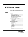
Figure 2-1 outlines how NI Requirements Gateway interacts with external
products. NI Requirements Gateway allows you to configure which
specification and working documents to process, configure the type of
traceability information to capture from each document, and specify the
traceability relationship between the specification and working documents.
You can navigate between documents in Requirements Gateway and the
external products.
© National Instruments Corporation
2-1
Getting Started with NI Requirements Gateway
Chapter 2
Introduction to NI Requirements Gateway
DOORS,
Access
Dedicated Interfaces
Requirements
Traceability
NI Requirements Gateway
Capture
Navigation
Dedicated Interfaces
TestStand
LabVIEW
LabWindows/CVI
MATRIXx
Figure 2-1. NI Requirements Gateway Overview
NI Requirements Gateway performs coverage and impact analysis,
graphically displays relationships between documents, and generates
comprehensive reports. NI Requirements Gateway is an effective solution
for enhancing project management by linking traceability information from
any source it comes from.
NI Requirements Gateway includes the following features that allow
you to:
•
Manage project documents and graphically create traceability
relationships between documents
•
Customize types for importing various types of data from National
Instruments and third-party products
•
Use coverage analysis, impact analysis, and graphical views to
visualize and analyze traceability relationships between documents
•
Create filters to customize analysis and views
Getting Started with NI Requirements Gateway
2-2
ni.com
Chapter 2
Introduction to NI Requirements Gateway
•
Capture and compare project snapshots to determine changes in
requirements and coverage
•
Generate reports using default and custom templates
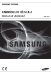
Starting Requirements Gateway
When you launch Requirements Gateway, the main window is visible, as
shown in Figure 2-2.
1
2
3
4
5
6
1
2
Toolbar
Menu Bar
3
4
Filter Ring Control
View Tabs
5
6
Project Workspace
Status Bar
Figure 2-2. Requirements Gateway Main Window
© National Instruments Corporation
2-3
Getting Started with NI Requirements Gateway
Chapter 2
Introduction to NI Requirements Gateway
Introduction to Requirements Gateway
The main window has four main parts: the menu bar, toolbar, project
workspace, and status bar.
Menu Bar
The menu bar contains the following menus: File, Edit, View, Tools,
Reports, and Help. Browse the menus in the menu bar of the main window
to familiarize yourself with their contents. The status bar displays a brief
explanation when you hover over an item in the menu.
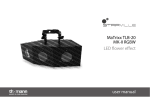
Toolbar
The toolbar contains shortcuts to commonly used selections of the menu
bar. Figure 2-3 shows the following six sections in the toolbar: Standard,
Configuration, Navigation, View Options, Filtering, and Third Party.
1
1
2
2
3
Standard
Configuration
4
3
4
5
Navigation
View Options
5
6
6
Filtering
Third Party
Figure 2-3. Requirements Gateway Toolbar
•
Standard—Contains buttons for creating, loading, and saving project
files.
•
Configuration—Contains buttons for configuring projects, types, and
snapshots.
•
Navigation—Contains buttons to apply navigation commands
previously performed within the coverage information of the Coverage
Analysis View and Impact Analysis View.
•
View Options—Contains buttons to control which traceability
elements are visible in the Management View, Coverage Analysis
View, and Impact Analysis View.
•
Filtering—Contains the Filter ring control to configure and apply
filters that specify the conditions by which to include requirements in
an analysis or view.
•
Third Party—Contains a button that applies to specific third-party
products, such as Telelogic DOORS.
Getting Started with NI Requirements Gateway
2-4
ni.com
Chapter 2
Introduction to NI Requirements Gateway
Project Workspace
The project workspace is the main part of the application. It displays the
project information and analysis for the loaded project. The project
workspace contains tabs for displaying the contents of the project in
different views. Each view may contain one or more panes.
The project workspace contains the following views:
•
Management View—Displays the documents in the project, the
elements of each document, and a summary of coverage information
for the project.
•
Coverage Analysis View—Displays one level of covering elements,
N–1, for a selected element of a document, and one level of covered
elements, N+1, from other documents as defined by the project.
•
Impact Analysis View—Displays all levels of covering elements,
N–m, for a selected element of a document, and all levels of covered
elements, N+p, from other documents as defined by the project.
•
Graphical View—Displays each document graphically using a tree
view with lines connecting requirement elements in documents and
covering elements in other documents.
•
Requirement Details—Displays each requirement and its attributes
for a document in a table.
Status Bar
The status bar displays common information in the application, such as
descriptions for menu items or status while performing analysis.
© National Instruments Corporation
2-5
Getting Started with NI Requirements Gateway
Chapter 2
Introduction to NI Requirements Gateway
Configuration Dialog Box
Requirements Gateway launches the Configuration dialog box when you
select a menu item or toolbar button to configure one of the following parts
of your project: Project, Types, Snapshots, Filters, Reports, Expressions, or
Options. The Configuration dialog box is shown in Figure 2-4.
Figure 2-4. Requirements Gateway Configuration Dialog Box
The Configuration dialog box contains the following panes:
•
Project—Allows you to configure the project by specifying the
documents to include, the type of each document, and the covering
relationship between documents. Refer to Chapter 4, Project
Configuration, in the NI Requirements Gateway User Manual located
in the Help menu of the main window for more information about
configuring projects.
•
Types—Allows you to create new types or customize existing types
for your project. Refer to the NI Requirements Gateway Customization
Guide located in the Help menu of the main window for more
information about customizing types.
Getting Started with NI Requirements Gateway
2-6
ni.com
Chapter 2
Introduction to NI Requirements Gateway
•
Snapshots—Allows you to create, manage, and compare snapshots of
your project. Refer to Chapter 7, Snapshot Management, in the
NI Requirements Gateway User Manual for more information about
using snapshots.
•
Filters—Allows you to define custom filters to analyze or display
certain requirements from documents that meet specific criteria. You
can enable filters using the Filter ring control on the toolbar in the
Requirements Gateway main window. Refer to the Filters section of
Chapter 5, Project Analysis, in the NI Requirements Gateway User
Manual for more information about using filters.
•
Reports—Allows you to define new custom reports. You can generate
a default report or a custom report using the Reports»Library
Reports submenu in the main window. Refer to Chapter 8, Generating
Documentation, in the NI Requirements Gateway User Manual for
more information about generating reports.
•
Expressions—Allows you to test regular expressions. You can specify
source text and a regular expression, and the pane displays the captured
text returned by the regular expression.
•
Options—Allows you to set the default font for the text in the
application, set the password for the project, define environmental
variables, and specify other miscellaneous settings for the application.
In the next chapter, you learn about the different windows and views in
Requirements Gateway.
© National Instruments Corporation
2-7
Getting Started with NI Requirements Gateway
3
Managing Requirements
In this chapter, you learn about the different windows and views in
Requirements Gateway by creating a project, adding existing documents to
the project, and reviewing the contents of the documents.
A project specifies the documents that Requirements Gateway analyzes and
displays. A project also specifies which type to use for each document. A
type defines how to select external files that represent a document, how to
read the contents of the external files, how to interpret the contents as
elements for managing requirements, and how to display the elements of
the document.
Requirements Gateway contains a set of predefined types for the following
data sources:
•
Microsoft Word documents
•
Microsoft Excel spreadsheets
•
Telelogic DOORS databases
•
IBM Rational RequisitePro databases
•
TestStand sequence files and XML reports
•
MATRIXx SystemBuild catalogs
•
LabVIEW VIs
•
LabWindows/CVI source code and function panel files
•
Microsoft Access database files
•
Acrobat PDF files
•
Microsoft Visio project files
•
Generic text files
•
Generic source code files
© National Instruments Corporation
3-1
Getting Started with NI Requirements Gateway
Chapter 3
Managing Requirements
Creating a Project
Note The exercises in this manual modify the tutorial files located in the <Requirements
Gateway>\Tutorial directory. You can restore the tutorial files to their original state by
copying the files from the <Requirements Gateway>\Tutorial\Original directory
into the <Requirements Gateway>\Tutorial directory.
In this exercise, you learn how to start the Requirements Gateway
application and create a new project. You also learn how to add and
configure documents in the project, review the contents of the documents,
and use the views in the Requirements Gateway project workspace.
1.
Launch Requirements Gateway by selecting Start»All Programs»
National Instruments»Requirements Gateway 1.0»
Requirements Gateway. You should now see the Requirements
Gateway main window.
2.
Select File»New to launch the Create a New Project and Save As
dialog box, and navigate to the <Requirements Gateway>\
Tutorial directory.
3.
Enter MyProject in the File name control and click Save.
Requirements Gateway creates a new project file, MyProject.rqtf, in
the <Requirements Gateway>\Tutorial directory and displays the
Project pane of the Configuration dialog box as shown in Figure 3-1. A
project file defines which documents Requirements Gateway reads, the
type of each document, and the covering relationship between those
documents.
Getting Started with NI Requirements Gateway
3-2
ni.com
Chapter 3
1
Managing Requirements
2
3
4
1
Project Tree
2
Traceability Description Zone
3
Action Buttons
4
Document Details
Figure 3-1. New Project in Configuration Dialog Box
Adding a Document
In this section, you learn how to add a specification document to the project
you created in the Creating a Project section of this chapter.
1.
Click the Add a document button. The cursor automatically moves to
the Traceability Description Zone and the cursor outlines a document
object. Click within the Traceability Description Zone to place the
document.
When you place the document, the document is added to the Project
Tree pane. The Document Details pane displays the settings for the
selected document in the Project Tree pane.
© National Instruments Corporation
3-3
Getting Started with NI Requirements Gateway
Chapter 3
Managing Requirements
2.
In the Document Details pane, click in the Name column to select the
Document1 text. Type Product Specification and press
<Enter> to rename the document. The name in the document object
now displays the new name.
3.
Click in the Type of Analysis column and select Text in the ring
control to instruct Requirements Gateway to analyze the document
using the Text type.
4.
Click in the File or Directory column. The File Browse button is now
visible on the right side of the control. Click the File Browse button
and select <Requirements Gateway>\Tutorial\
ProductSpec.txt. Figure 3-2 displays the completed Configuration
dialog box.
Figure 3-2. Adding a Document to a New Project
Getting Started with NI Requirements Gateway
3-4
ni.com
Chapter 3
Managing Requirements
Adding a Covering Document
A covering document is a document that contains references to
requirements that are defined in another document. In this section, you
learn how to add a new document to the project that covers the Product
Specification document.
1.
Click the Add a document button to add a second document in the
Traceability Description Zone. Place the document below the Product
Specification document.
2.
In the Document Details pane, enter Covering Specification in
the Name control, select Text from the Type of Analysis ring control,
and browse to <Requirements Gateway>\Tutorial\
CoveringSpec.txt in the File or Directory control.
© National Instruments Corporation
3-5
Getting Started with NI Requirements Gateway
Chapter 3
Managing Requirements
3.
Click the Add a cover button. The cursor moves to the Traceability
Description Zone. Click the Covering Specification document and
then click the Product Specification document. An arrow is now
visible between the two documents as shown in Figure 3-3. This arrow
indicates that the Covering Specification document covers the Product
Specification document.
Figure 3-3. Covering Document in Project
4.
Click OK to close the Configuration dialog box.
Getting Started with NI Requirements Gateway
3-6
ni.com
Chapter 3
Managing Requirements
Using the Management View
After you close the Configuration dialog box in step 4 of the Adding a
Covering Document section, the main window is visible as shown in
Figure 3-4.
Figure 3-4. Management View
The upper left section of the Management View displays a list of the
documents defined by the project in a tree view pane. The tree view pane
contains two root nodes, one for each of the documents that you added to
the project. The Project Synthesis Information section indicates that the
project has two documents with ten defined requirements and one
uncovered requirement.
Complete the following steps to familiarize yourself with the Management
View and the documents that you included in the project.
1.
© National Instruments Corporation
Right-click the Product Specification document in the tree view pane
and select Navigate from the context menu. Requirements Gateway
3-7
Getting Started with NI Requirements Gateway
Chapter 3
Managing Requirements
displays ProductSpec.txt in an external application as shown in
Figure 3-5.
Note Requirements Gateway launches the application that is associated with .txt files
for your computer. The default application for Windows 2000 and Windows XP is
Microsoft Notepad.
1
2
3
4
5
6
7
1
2
General Text
Document Text
3
4
Section
Section Text
5
6
Requirement ID
Requirement Label
7
Requirement Text
Figure 3-5. ProductSpec.txt Document
2.
Review the contents of the text file in the external application.
ProductSpec.txt specifies ten requirements.
The file contains three types of elements: sections, requirements, and
text. The default Text type in Requirements Gateway interprets the
contents of the file as follows:
•
Section—Defined by numeric heading characters such as 2.1.
The text after the numeric heading is the section’s text.
•
Requirement—Defined by an identifier that contains a set of
arbitrary characters, followed by the characters, REQ, and ending
with a numeric value. The label for the requirement is located after
the identifier and is delimited by a colon character.
Getting Started with NI Requirements Gateway
3-8
ni.com
Chapter 3
•
Managing Requirements
Text—When delimited by the << and >> characters, the text is
associated with the previously specified element. If an initial text
element is specified at the beginning of the file, the text is
associated with the document.
3.
Exit the application that is displaying ProductSpec.txt.
4.
In Requirements Gateway, select the Covering Specification
document in the tree view pane.
5.
Right-click the Covering Specification document and select
Navigate from the context menu. Requirements Gateway displays
CoveringSpec.txt in an external application.
6.
Review the contents of the text file in the external application.
CoveringSpec.txt contains section and text elements, but instead
of requirements, the file contains references to requirements. A
reference is defined by the prefix characters [Covers:, followed by a
set of characters that represent the requirement identifier, and
completed with a closing bracket character.
CoveringSpec.txt specifies nine requirement references. Notice
that the 1.2. USB 2.0 Speeds section of the document does not contain
a requirement reference. This missing reference is discussed in step 16
of this exercise.
7.
Exit the application that is displaying CoveringSpec.txt.
8.
In Requirements Gateway, select the Product Specification document
in the tree view pane. The tree view pane displays the percentage of
covered requirements for a document, which is 90% for this document.
The Selection Info section in the lower left corner of the window
indicates that the document defines ten requirements, and one of the
requirements is uncovered.
© National Instruments Corporation
3-9
Getting Started with NI Requirements Gateway
Chapter 3
Managing Requirements
9.
Expand the child elements of the Product Specification document in
the tree view pane of the Management View as shown in Figure 3-6.
To expand a parent element and all its child elements, press <Shift> while clicking
the plus icon to expand the parent element.
Note
The tree view pane displays the section headings from the text file as
parent elements and displays the requirements as child elements.
Figure 3-6. Product Specification in Management View
10. Select the PS_USB_REQ1 element in the tree view pane. The
PS_USB_REQ1 element represents a requirement specified in the
document. The Selection Info section indicates that the
PS_USB_REQ1 element is a requirement and that the requirement is
covered.
11. Select the PS_USB_REQ2 element in the tree view pane. The
Selection Info section indicates that the PS_USB_REQ2 element is
also a requirement; however, the requirement is not covered.
Requirements Gateway highlights the element name in red.
12. Collapse the Product Specification document in the tree view pane of
the Management View.
13. Select the Covering Specification document in the tree view pane.
The Selection Info section indicates that the document contains nine
references to requirements.
Getting Started with NI Requirements Gateway
3-10
ni.com
Chapter 3
Managing Requirements
14. Expand the child elements of the Covering Specification document in
the tree view pane of the Management View, as shown in Figure 3-7.
Figure 3-7. Covering Specification in Management View
15. Select the 1.1 USB 1.0 Speeds element. The element represents a
section specified in the document. The Selection Info section indicates
that the section contains a reference to one requirement.
16. Select the 1.2 USB 2.0 Speeds element. The Selection Info section for
this element indicates that the section is empty and contains no
references to any requirements.
17. Collapse the Covering Specification document in the tree view pane
of the Management View.
18. Expand the elements of the Rules Check section of the Management
View, as shown in Figure 3-8. The Rules Check section contains a
summary of the rules flagged from analyzing the project. For this
project, the section indicates that the PS_USB_REQ2 requirement is
uncovered.
Figure 3-8. Rules Check Section of the Management View
© National Instruments Corporation
3-11
Getting Started with NI Requirements Gateway
Chapter 3
Managing Requirements
Refer to Chapter 6, Computations and Checks, in the NI Requirements
Gateway User Manual for more information about the various rules
that Requirements Gateway defines.
You have completed this section of the tutorial. In the next chapter, you
learn how to analyze the project using additional views in Requirements
Gateway.
Getting Started with NI Requirements Gateway
3-12
ni.com
Analyzing Requirements
4
As you learned in Chapter 3, Managing Requirements, the Management
View summarizes the documents in the project, the structure and
requirement-related information in each document, and any rules related to
the project. This chapter teaches you how to use the Coverage Analysis
View, the Impact Analysis View, and the Graphical View to obtain
additional details about the requirements and the references that cover
them.
© National Instruments Corporation
4-1
Getting Started with NI Requirements Gateway
Chapter 4
Analyzing Requirements
Using the Coverage Analysis View
Complete the following steps to analyze requirement coverage for the
project that you created in Chapter 3, Managing Requirements.
1.
Click the Coverage Analysis View tab in the main window. Check to
make sure that the Product Specification and the Covering
Specification documents in the Selection column are collapsed, as
shown in Figure 4-1.
Figure 4-1. Coverage Analysis View
The Coverage Analysis View is divided into three columns. The
columns in the upper half of the view contain the following tree view
panes:
•
Upstream Coverage Information—For a selected document in
the Selection column, the Upstream Coverage Information tree
view pane displays one level of covered requirements, N–1, from
other documents as defined by the project.
•
Selection—Displays the contents of the documents in the project.
Getting Started with NI Requirements Gateway
4-2
ni.com
Chapter 4
•
Analyzing Requirements
Downstream Coverage Information—For a selected document
in the Selection column, the Downstream Coverage Information
tree view pane displays one level of covering requirement
reference elements, N+1, from other documents as defined by the
project.
The lower half of the Coverage Analysis View contains the following
three tabs. Each tab is divided into three columns that display details
about the selected element in the upper half of the view.
•
Texts and Reference Attributes—Displays the text for the
selected element and any reference attributes for references
linking the selection in the Selection column to the corresponding
element in the Upstream Coverage Information or Downstream
Coverage Information column.
•
Attributes—Displays the attributes for the selected element.
•
Messages—Displays helpful information, including rule
violation details, for the selected element in the Selection column.
2.
Click the Product Specification document in the Selection column.
The Downstream Coverage Information column displays that the
Product Specification document is covered by the Covering
Specification document, and that the document covers 90% of the
requirements.
3.
Expand the child elements of the Product Specification document in
the Selection column.
4.
Click the PS_USB_REQ1 requirement as shown in Figure 4-2. The
Downstream Coverage Information column displays the 1.1 USB 1.0
Speeds section as a covering element because this section of the
document contains a reference to the requirement. The tree view pane
also includes the parent, 1 USB Support section of the covering
document.
Figure 4-2. PS_USB_REQ1 Selected in Coverage Analysis View
© National Instruments Corporation
4-3
Getting Started with NI Requirements Gateway
Chapter 4
Analyzing Requirements
5.
Click the PS_USB_REQ2 requirement as shown in Figure 4-3. The
Downstream Coverage Information column does not display any
covering elements because the covering document does not contain a
reference to the requirement.
Figure 4-3. PS_USB_REQ2 Selected in Coverage Analysis View
6.
Hover over the exclamation icon to the right of the PS_USB_REQ2
requirement to display a tooltip that contains the text, 1 uncovered
requirement. The Selection column displays the exclamation icon
for an uncovered requirement and its parent elements in the document.
7.
Click the 2 Analog Channels section as shown in Figure 4-4. The
child elements of the Analog Channels section contain four
requirements: PS_AI_REQ1, PS_AI_REQ2, PS_AO_REQ1, and
PS_AO_REQ2. The Downstream Coverage Information column
displays both the 2.1 Analog Input and the 2.2 Analog Output sections
as covering elements. In the covering document, the 2.1 Analog Input
section contains references to the PS_AI_REQ1 and PS_AI_REQ2
requirements and the 2.2 Analog Output section contains references to
the PS_AO_REQ1, and PS_AO_REQ2 requirements.
Figure 4-4. 2 Analog Channels Section Selected in Coverage Analysis View
Getting Started with NI Requirements Gateway
4-4
ni.com
Chapter 4
8.
Analyzing Requirements
Double-click the 2.1 Analog Input section in the Downstream
Coverage Information column. Requirements Gateway navigates to
the 2.1 Analog Input section in the Selection column, as shown in
Figure 4-5. The Upstream Coverage Information column displays that
90% of the requirements in the Product Specification document are
covered by the Covering Specification document, and that the
PS_AI_REQ1 and, PS_AI_REQ2 requirements are specifically
covered by references from the 2.1 Analog Input section in the
Selection column.
Figure 4-5. 2.1 Analog Input Section Selected in Coverage Analysis View
9.
Expand the 1 USB Support section of the Covering Specification
document to view the 1.2 USB 2.0 Speeds element.
10. Double-click the 1.2 USB 2.0 Speeds element in the Selection column
to launch CoveringSpec.txt in an external application.
11. Edit the file by adding a reference to the PS_USB_REQ2 requirement
below the 1.2. USB 2.0 Speeds section as shown in Figure 4-6.
1. USB Support
1.1. USB 1.0 Speeds
<<Hardware supports USB 1.0>>
[Covers: PS_USB_REQ1]
1.2. USB 2.0 Speeds
<<Hardware supports USB 2.0>>
[Covers: PS_USB_REQ2]
2. Channel Support
2.1. Analog Input
<<Hardware supports analog input>>
[Covers: PS_AI_REQ1]
<<10 channels>>
[Covers: PS_AI_REQ2]
Figure 4-6. PS_USB_REQ2 Reference in Covering Document
© National Instruments Corporation
4-5
Getting Started with NI Requirements Gateway
Chapter 4
Analyzing Requirements
12. Save the changes to CoveringSpec.txt and exit the application.
13. Return to Requirements Gateway. When the main window of
Requirements Gateway is displayed, the application prompts you
indicating that the Covering Specification document was modified.
Click Yes to reload the file. Requirements Gateway analyzes the new
document and updates the view as shown in Figure 4-7.
Figure 4-7. Covering Specification Document After Reload
The Upstream Coverage Information column now indicates that the
Covering Specification document covers 100% of the requirements in
the Product Specification document, the PS_USB_REQ2 requirement
is now shown as covered by the 1.2 USB 2.0 Speeds element, and the
icon for the 1.2 USB 2.0 Speeds element and its parent elements
indicate a change occurred.
In summary, the Coverage Analysis View allows you to select elements
from a project document and display requirement coverage one level
upstream and one level downstream from the selected document. In the
next exercise, you learn how to use the Impact Analysis View.
Getting Started with NI Requirements Gateway
4-6
ni.com
Chapter 4
Analyzing Requirements
Using the Impact Analysis View
The Impact Analysis View displays traceability information from all
downstream and upstream documents, as opposed to the Coverage
Analysis View, which displays only the immediate downstream and
upstream documents.
In this exercise, you learn how to add a third document to the project and
how to use the Impact Analysis View.
Adding a Second Downstream Document
Complete the following steps to add a third document to MyProject.rqtf
that you created in Chapter 3, Managing Requirements.
1.
Select File»Edit Project to launch the Project pane of the
Configuration dialog box.
2.
Click the Covering Specification document in the Traceability
Description Zone.
3.
In the Document Details pane, enter Design Specification in the
Name control, select Text in the Type of Analysis ring control, and
browse to <Requirements Gateway>\Tutorial\
DesignSpec.txt in the File or Directory control.
4.
Click the Add a document button to add a third document in the
Traceability Description Zone. Place the document below the Design
Specification document.
5.
In the Document Details pane, enter Test Specification in the
Name control, select Text in the Type of Analysis ring control, and
browse to <Requirements Gateway>\Tutorial\TestSpec.txt
in the File or Directory control.
6.
Click the Add a cover button to begin adding a covering link.
Click the Test Specification document and then click the Design
Specification document to create an arrow between the
two documents as shown in Figure 4-8.
© National Instruments Corporation
4-7
Getting Started with NI Requirements Gateway
Chapter 4
Analyzing Requirements
Figure 4-8. Two Levels of Covering Documents in Project
7.
Click OK to close the Configuration dialog box.
8.
Click Yes when Requirements Gateway prompts you to reanalyze the
project. Your new project is now properly configured to analyze the
new documents.
9.
Return to the Requirements Gateway main window and click the
Impact Analysis View tab.
10. Collapse the three documents in the Selection column.
Reviewing the New Documents
Complete the following steps to review the contents of the two new
documents:
1.
Double-click the Design Specification document in the Selection
column to display DesignSpec.txt in an external application.
Getting Started with NI Requirements Gateway
4-8
ni.com
Chapter 4
2.
Analyzing Requirements
Review the contents of the text file in the external application.
DesignSpec.txt contains similar sections and text elements as
found in CoveringSpec.txt, but DesignSpec.txt also contains
25 additional requirements. These additional requirements are covered
by references in the Test Specification document.
Figure 4-9 displays the 1.1 USB 1.0 Speeds section of the file, which
contains a reference to the PS_USB_REQ1 requirement and contains
two additional derived requirements, DS_USB1_REQ1 and
DS_USB1_REQ2. A derived requirement is a requirement that is
defined in a document but is not directly associated with the coverage
of an upstream document.
1. USB Support
1.1. USB 1.0 Speeds
<<Hardware supports USB 1.0>>
[Covers: PS_USB_REQ1]
DS_USB1_REQ1: Low Speed
<<1.5 Mbps>>
DS_USB1_REQ2: High Speed
<<12 Mbps>>
1.2. USB 2.0 Speeds
<<Hardware supports USB 2.0>>
Figure 4-9. Derived Requirements in Design Specification
To associate a requirement with the coverage of an upstream
document, you must specify the requirement immediately before the
reference that covers the upstream document as shown in Figure 4-10.
These requirements are sometimes referred to as non-derived
requirements.
1.2. USB 2.0 Speeds
<<Hardware supports USB 2.0>>
DS_USB2_REQ1: Low Speed
<<1.5 Mbps>>
[Covers: PS_USB_REQ2]
DS_USB2_REQ2: Med Speed
<<12 Mbps>>
[Covers: PS_USB_REQ2]
DS_USB2_REQ3: High Speed
<<480 Mbp>>
[Covers: PS_USB_REQ2]
Figure 4-10. Non-Derived Requirements in Design Specification
© National Instruments Corporation
4-9
Getting Started with NI Requirements Gateway
Chapter 4
Analyzing Requirements
Requirements Gateway displays derived and non-derived requirements
in the Impact Analysis View.
3.
Exit the application that is displaying DesignSpec.txt.
4.
Double-click the Test Specification document in the Selection
column to launch TestSpec.txt in an external application.
5.
Review the contents of the text file in the external application.
TestSpec.txt contains 25 references for the requirements specified
in the Design Specification document.
6.
Exit the application that is displaying TestSpec.txt.
Performing Impact Analysis
Complete the following steps to learn how to analyze the new documents
using the Impact Analysis View:
1.
Expand the Design Specification document in the Selection column to
display the derived requirements, DS_USB1_REQ1 and
DS_USB1_REQ2, and the non-derived requirements,
DS_USB2_REQ1, DS_USB2_REQ2, and DS_USB2_REQ3, as
shown in Figure 4-11. Requirements Gateway displays different icons
for derived and non-derived requirements, and displays a navigation
arrow icon to the right side of the requirement to highlight derived
requirements.
Figure 4-11. Derived and Non-Derived Requirements
Getting Started with NI Requirements Gateway
4-10
ni.com
Chapter 4
2.
Analyzing Requirements
Expand the Product Specification document and select the
PS_USB_REQ1 requirement, as shown in Figure 4-12. The
Downstream Impact Information column displays only the covering
1.1 USB 1.0 Speeds section from the Design Specification document
because the 1.1 USB 1.0 Speeds section does not contain any
non-derived requirements that are covered by the Test Specification
document.
Figure 4-12. PS_USB_REQ1 Downstream Impact Analysis
3.
Select the PS_USB_REQ2 requirement as shown in Figure 4-13. The
Downstream Impact Information column displays the non-derived
requirements from the covering Design Specification document, but
also the sections from the Test Specification document that cover the
non-derived requirements.
Figure 4-13. PS_USB_REQ2 Downstream Impact Analysis
In the next section, you learn how to graphically view traceability
information.
© National Instruments Corporation
4-11
Getting Started with NI Requirements Gateway
Chapter 4
Analyzing Requirements
Using the Graphical View
The Graphical View displays each document as an object with its
traceability elements displayed in a tree view within the object. Thin, black
lines represent covering references between requirements elements of a
document and elements in another document. You can also reposition
documents, adjust the width of the documents, pan, zoom, and resize the
containing page.
Complete the following steps to graphically view your project documents:
1.
Click the Graphical View tab.
2.
Select the PS_USB_REQ1 requirement in the Product Specification
document. The Graphical View highlights the PS_USB_REQ1
requirement, the covering 1.1 USB 1.0 Speeds section, and the line
between the elements, as shown in Figure 4-14.
Getting Started with NI Requirements Gateway
4-12
ni.com
Chapter 4
Analyzing Requirements
Figure 4-14. PS_USB_REQ1 Selected in Graphical View
3.
© National Instruments Corporation
Select the PS_USB_REQ2 requirement. The Graphical View
highlights the PS_USB_REQ2 requirement and additional elements
from the two downstream documents.
4-13
Getting Started with NI Requirements Gateway
Chapter 4
Analyzing Requirements
4.
Right-click in the Graphical View and select View Graph for
Selection from the context menu. When you make this selection, the
view only displays the highlighted elements from the three documents,
as shown in Figure 4-15.
Figure 4-15. PS_USB_REQ2 Selected in Graphical View
5.
Right-click in the Graphical View and select Show All Elements from
the context menu to display all the elements of the documents again.
6.
Click the header of the Test Specification document to select the entire
document.
7.
Right-click the Test Specification document and select Hide Selected
Documents from the context menu. The Graphical View hides the Test
Specification document and displays the traceability information for
the remaining two documents.
8.
Right-click in the Graphical View and select Show All Elements in the
context menu to display all of the documents again.
As your document gets larger or more complex, you can perform the
following tasks to control the Graphical View:
•
Resize the Graphical View by selecting the lower right corner of the
page and dragging the page corner to increase or decrease the page
size.
•
Move the documents within the Graphical View by selecting the
document header and dragging the header to a new location.
•
Resize the width of a document by selecting the document header and
dragging the resize handles that appear on the right side of the
document.
•
Zoom in and out by pressing <Ctrl> while rolling your mouse wheel
up or down, or by selecting either Zoom»100% or Zoom»Fit in page
from the context menu.
In the next chapter, you learn how to generate reports for a project.
Getting Started with NI Requirements Gateway
4-14
ni.com
5
Generating Reports
In this chapter, you learn how to generate reports and create customized
reports.
Generating a Built-in Report
NI Requirements Gateway installs the following library reports:
•
Traceability Matrix—Lists the upstream to downstream covered
links and the downstream to upstream covering links.
•
Analysis Results—Summarizes the coverage analysis for a project.
•
Project Description—Describes the project and its documents.
•
Upstream Impact Analysis—Lists the upstream traceability
information for selected elements of the project.
•
Downstream Impact Analysis—Lists the downstream traceability
information for selected elements of the project.
•
Synthesis of Added Information—Summarizes any added attributes,
references, text, and covering links in the project.
•
Rules Checking—Contains a summary of any rules highlighted by the
project.
Complete the following steps to generate a Project Description report for
the project that you created in Chapter 4, Analyzing Requirements.
1.
Click the Management View tab in the main window. Check to make
sure that the documents are collapsed in the tree view pane.
2.
Select Reports»Library Reports»Project Description to display the
Save As dialog box.
© National Instruments Corporation
5-1
Getting Started with NI Requirements Gateway
Chapter 5
Generating Reports
3.
Check to make sure you are in the <Requirements Gateway>\
Tutorial directory, enter ProjectDescription in the file name
control, and click Save. Requirements Gateway generates and displays
the report in Microsoft WordPad or Microsoft Word, as shown in
Figure 5-1.
4.
Review the contents of the report.
Figure 5-1. Project Description Report
5.
Exit the application that is displaying the report.
Getting Started with NI Requirements Gateway
5-2
ni.com
Chapter 5
Generating Reports
Creating a Custom Report
Refer to the Customizing Reports chapter in the NI Requirements Gateway
Customization Guide for more information about customizing reports.
Complete the following steps to create a custom report that lists the
requirements defined in each document of the project.
1.
Select Reports»Edit Reports to display the Reports pane of the
Configuration dialog box.
2.
Click the New report button. Requirements Gateway adds a new
report to the project as shown in Figure 5-2.
1
2
3
4
1
Report
2
Report List
3
Toolbar
4
Properties
Figure 5-2. Reports Pane of Configuration Dialog Box
© National Instruments Corporation
5-3
Getting Started with NI Requirements Gateway
Chapter 5
Generating Reports
The Reports pane consists of the following sections:
•
Report—Displays the active report selected in the Report List.
•
Report List—Lists the reports defined by the application and the
reports defined by the project.
•
Toolbar—Contains buttons to create, rearrange, and delete
reports from the Report List. In addition, the Report elements
button toggles the controls below the Report List to either display
the properties of the selected item in the report or the available
properties to insert in the report.
•
Properties—Contains the following sections which display
separately when you toggle the Report elements button.
–
Properties of selected item—Displays the settings
associated with the active element selected in the report.
–
Available properties to insert—Displays the elements that
you can insert into the report. When you select an element of
the report, valid elements that you can insert into the selected
element are highlighted with bold text.
3.
Enter Requirements in the English name control.
4.
Select portrait.rtf in the Template ring control.
5.
Select the Requirements object in the report. The Requirements
object is highlighted.
6.
Click the Report elements button to display the Available properties
to insert section.
The Available properties to insert section contains the following
three tabs:
7.
•
Structures—Contains elements that define the structure of the
report, such as text, paragraph, list, or table.
•
Data—Contains elements associated with the object you select in
the report, such as the project, a document, or a requirement.
•
Parameters—Contains data type elements that you can pass to a
structure element.
Click the Data tab.
Getting Started with NI Requirements Gateway
5-4
ni.com
Chapter 5
8.
Generating Reports
Select the project»Contents»analyzed documents element and drag
and drop the element to the selected item in the report as shown in
Figure 5-3.
Figure 5-3. Inserted Analyzed Documents Element
The analyzed documents element directs the report to loop on all of the
documents in the project.
9.
Click the Report elements button to display the Properties of selected
item section. Notice that the Variable name control value defaults to
doc1. This variable represents the active document while looping on
all documents in the project.
10. Click the Report elements button and click the Structures tab.
11. Select the paragraph element and drag and drop the element to the
analyzed documents element. Requirements Gateway adds a
paragraph to the report for each document in the project.
Steps 12 through 24 define the structure and content of the paragraphs.
12. Select the text element and drag and drop the element to the paragraph
element.
13. Select the Report elements button and enter Document: in the
English text control.
14. Click to the right of the Document: text element in the report to
highlight the entire paragraph element.
15. Click the Report elements button and click the Data tab.
16. Select the doc1»Identification information»name element and drag
and drop the element to the right of the Document: text element as
shown in Figure 5-4.
Figure 5-4. Inserted Name of Doc1 Element
© National Instruments Corporation
5-5
Getting Started with NI Requirements Gateway
Chapter 5
Generating Reports
17. Select the analyzed documents of project : doc1 element in the
report.
18. Click the Structures tab.
19. Select the table element and drag and drop the element to the bottom
of the analyzed document of project element.
20. Drag and drop a text element to each of the elements in the upper half
of the table and assign Requirement and Text to each of the table
header elements.
21. Select the area below the column headers as shown in Figure 5-5.
Figure 5-5. Inserted Column Text Elements
22. Drag and drop the doc1»Contents»requirements element from the
Data tab to the lower half of the table.
23. Drag and drop the table row element from the Structures tab to the
requirements of doc1 element.
24. Drag and drop the req1»Identification information»display element
and the req1»Identification information»text element from the Data
tab to each of the cells in the new table row as shown in Figure 5-6.
Figure 5-6. Final Custom Report
Getting Started with NI Requirements Gateway
5-6
ni.com
Chapter 5
Generating Reports
25. You have completed creating your custom report. Click OK to close
the Configuration dialog box.
26. Select Reports»Project Reports»Requirements from the main
window to display the Save As dialog box.
© National Instruments Corporation
5-7
Getting Started with NI Requirements Gateway
Chapter 5
Generating Reports
27. Enter Requirements in the file name control and click Save.
Requirements Gateway generates and displays the report file in
Microsoft WordPad or Microsoft Word, as shown in Figure 5-7.
28. Review the contents of the report.
Figure 5-7. Final Generated Report
29. Exit the application that is displaying the report.
Getting Started with NI Requirements Gateway
5-8
ni.com
6
Customizing Types
The organization and formatting of data can vary between documents,
and does not always adhere to the format required by the default
implementation of a type. In this case, you can either modify the document
to conform to the format required by the type, or you can create a custom
type that processes the format defined by the document. In this chapter, you
learn how to customize the definition of a type to conform to the data
format in a file.
Review File Formats
For most types, NI Requirements Gateway captures potential traceability
information by translating an external file, such as a Microsoft Word
document, into an intermediate text or XML file. The type analyzes the
intermediate file and captures the required structure and traceability
information. Refer to the NI Requirements Gateway Customization Guide
and the coupling document for the specific type to understand the content
and format of the intermediate text or XML file. You can open the
documents by selecting Documentation from the Help menu in the
Requirements Gateway main window.
The Text type directly processes the contents of a text file, without the use
of a translated intermediate file. In this section, you will evaluate the format
of a text file and customize a type to analyze the contents of the file.
Complete the following steps to review the contents of the files that the
custom type analyzes:
1.
Select File»Open to launch the Open dialog box and navigate to the
<Requirements Gateway>\Tutorial directory.
2.
Select CustomTypeProject.rqtf in the list control and click Open.
Requirements Gateway opens the project file and displays the
documents in the main window.
3.
Click the Management View tab and collapse all of the documents in
the tree view pane.
4.
Double-click the Product Specification document in the tree view
pane to launch CustomProductSpec.txt in an external application.
© National Instruments Corporation
6-1
Getting Started with NI Requirements Gateway
Chapter 6
Customizing Types
5.
Review the contents of the text file in the external application.
Figure 6-1 displays a portion of the text from
CustomProductSpec.txt.
- USB Communication
[REQ: USB1] USB1
[REQ: USB2] USB2
# The hardware will
# Low & High Speeds
# Low, Med, and High
- Analog Channels
- Analog Input
# The hardware will
[REQ: AI] Analog Input
# +/- 12 Volts
[REQ: AI_COUNT] 10 channels
Figure 6-1. Text from CustomProductSpec.txt
6.
Double-click the Covering Specification document in the tree view
pane to launch CustomCoveringSpec.txt in an external
application.
7.
Review the contents of the text file in the external application.
Figure 6-2 displays a portion of the text from the file.
- USB Support
- USB 1.0 Speeds
[REF: USB1]
- USB 2.0 Speeds
[REF: USB2]
#Hardware supports USB
#Hardware supports USB
Figure 6-2. Text from CustomCoveringSpec.txt
The default Text type cannot recognize and analyze the requirements,
references, and text elements within these two documents. The Product
Specification and Coverage Specification documents contain the
following traceability formalisms:
•
Each document specifies two levels of sections. A first-level
section is preceded by a minus character, and a second-level
section is preceded by two space characters and a minus character.
•
Requirements are specified by [REQ: id], where id is a set of
characters that represent the requirement. You can also follow a
requirement with an optional text label.
•
References are specified by [REF: id], where id is a set of
characters that represents the requirement.
Getting Started with NI Requirements Gateway
6-2
ni.com
Chapter 6
•
8.
Customizing Types
Text associated with a section or requirement is specified by the
# character.
Exit the external applications.
Creating a Custom Type
When you customize a type, you have to decide whether to duplicate an
existing type or create a new type. Since the Product Specification and
Coverage Specification documents adhere to a very different formalism
than defined by the default Text type, you will create a new type.
Complete the following steps to create a new type:
1.
Select File»Edit Types to display the Types pane of the Configuration
dialog box. The Types pane contains the following three sections:
•
Types List—Displays the list of types available in Requirements
Gateway. The final folder in the list represents the custom types
defined for any projects in the directory of the current project file.
•
Type Toolbar—Contains buttons to copy, delete, and add new
elements to the types list or to the elements of a specific type.
•
Selection Properties—Displays the settings associated with the
selected type or element of a type in the tree view.
2.
Click the Tutorial folder in the tree view.
3.
Click the Add new element button. Requirements Gateway adds a
new element, Type, to the Tutorial folder in the tree view.
4.
Enter My Type in the Name control.
5.
Select Text in the Convert tool ring control to instruct Requirements
Gateway to interpret any document that uses the type as a general text
file, similar to the default Text type.
© National Instruments Corporation
6-3
Getting Started with NI Requirements Gateway
Chapter 6
Customizing Types
6.
Select Text in the Edit tool ring control to instruct Requirements
Gateway to launch the application associated with the file type when
you navigate to the document. Figure 6-3 displays the new type.
Figure 6-3. New Type Created
7.
Expand the child elements under the My Type element in the Types
List.
The elements under My Type in the tree view define how
Requirements Gateway identifies traceability information in an
intermediate text or XML file that represents the data extracted from a
project document. Type elements use regular expressions to specify
patterns in the text of the intermediate file for Requirements Gateway
to identify instances of an element. Types that use intermediate XML
files also specify the structure of the XML data to identify traceability
information.
Getting Started with NI Requirements Gateway
6-4
ni.com
Chapter 6
Customizing Types
Table 6-1 lists the elements that a type might define and the purpose of
each element. Chapters 7 through 11 and Appendix A in this manual
contain similar tables with information that is specific to the type that
the chapter discusses.
Table 6-1. Type Elements
Element
Section
Description
Specifies how to identify and display the structural elements for a
document. For example:
• Headings in a text or Microsoft Word file
• Files in a directory
• Rows in a database
• Sequences, step groups, and steps in a TestStand sequence file
Requirement
Specifies how to identify and display requirements for a document.
For example, a requirement element might interpret [REQ: reqid]
as a requirement, where reqid is the requirement identifier.
Macro-Requirement
Specifies how to identify and display macro-requirements for a
document. A macro-requirement element defines a starting location
and an ending location, where any requirement element between the
locations are associated with the macro-requirement. For example,
a macro-requirement element might interpret [MacroReq_reqid]
as a starting location and [End_of_MacroReq] as an ending
location, where reqid is the macro-requirement identifier.
Entity
Specifies how to identify and display an entity for a document. An
entity element is similar to a section element except that
Requirements Gateway triggers a rule violation if a reference
element does not follow an entity element.
Reference
Specifies how to identify references to requirements for a document.
Requirements Gateway does not display reference elements;
however the reference is associated with a preceding section or
entity element. For example, an element might interpret [Covers:
reqid] as a requirement, where reqid is the identifier of the
covered requirement.
Attribute
Specifies how to identify and display attributes of requirement
elements for a document. An attribute element has a name and a
Boolean, string, or numeric value. An attribute element might define
the priority or owner of a requirement.
© National Instruments Corporation
6-5
Getting Started with NI Requirements Gateway
Chapter 6
Customizing Types
Table 6-1. Type Elements (Continued)
Element
Description
Reference Attribute
Specifies how to identify and display attributes of reference
elements for a document. A reference attribute element has a name
and a Boolean, string, or numeric value. A reference attribute
element might define the type of coverage for a reference.
Link
Specifies how to identify and display a non-covering reference to a
requirement, or a reference to a section or entity. The link element
must refer to the identifier of the requirement, section, or entity. You
can use the link element to navigate from the link element to the
requirement, section, or entity element.
Text
Specifies how to identify text associated with a preceding section,
entity, requirement, or attribute element.
Picture
Specifies how to identify pictures associated with a preceding
section or entity element. NI Requirements Gateway 1.0 supports
images with EPS and WMF file formats.
8.
Select the section element in the tree view.
9.
Click the Add new element button. Requirements Gateway adds a
new section element named Section1 to the tree view.
Getting Started with NI Requirements Gateway
6-6
ni.com
Chapter 6
Customizing Types
10. Enter ^-[ \t]*([^#\n\r]*).*$ in the Regular expression control.
Figure 6-4 displays the new section element.
Figure 6-4. Regular Expression For Section1
© National Instruments Corporation
6-7
Getting Started with NI Requirements Gateway
Chapter 6
Customizing Types
This regular expression specifies the pattern of text to match in the file
to locate section elements and their text. Table 6-2 lists the components
that this expression contains.
Table 6-2. Section1 Regular Expression Components
Expression
Purpose
^
Specifies to start pattern matching at the beginning of a line.
-
Specifies that the next character must be the minus character.
[ \t]*
The surrounding bracket characters specify that a character must match
either a space or a tab character, and the asterisk specifies that the text
must contain zero or more matches.
( )
Specifies that any text that matches the inside pattern is returned as a
field. This returns the text associated with the section.
[^#\n\r]*
The ^ character specifies that the pattern cannot match any of the
following specified characters: #, new line, or a carriage return. This
forces the pattern to stop at the # character, if the # character exists.
.*
Specifies to match zero or more of any of the characters. This pattern
process the # character, if it exists, and any subsequent text.
$
Specifies to match the end of a line.
11. Click the Add new element button. Requirements Gateway adds a
new section element named Section2 under the Section1 element.
12. Enter ^[ \t][ \t]-[ \t]*([^#\n\r]*).*$ in the Regular
expression control. This regular expression is similar to the expression
in step 10, with the addition of two extra required spaces or tabs
preceding the minus character.
13. Select the requirement element in the tree view.
14. Click the Add new element button. Requirements Gateway adds a
new requirement element named Requirement1.
Getting Started with NI Requirements Gateway
6-8
ni.com
Chapter 6
Customizing Types
15. Enter \[REQ: ([^\]]+)\][ \t]*([^#\r\n]*) in the Regular
expression control. Table 6-3 lists the components that this expression
contains.
Table 6-3. Requirement1 Regular Expression Components
Expression
Purpose
\[REQ:
Specifies to match the characters, [REQ: followed by a space character.
Specifies to return one or more characters that do not include the
closing bracket character. This returns the requirement identifier.
([^\]]+)
Specifies to match the closing bracket character.
\]
Specifies to match zero or more space or tab characters.
[ \t]*
Specifies to return zero or more characters that do not include the
# character, new line, or carriage return. This returns the requirement
label.
([^#\r\n]*)
16. Select the reference element in the tree view.
17. Click the Add new element button. Requirements Gateway adds a
new section element named Reference1.
18. Enter \[REF: ([^\]]+) in the Regular expression control. This
regular expression specifies to return one or more characters between
the space character after [REF: and the closing bracket character. This
returns the requirement identifier for the reference.
19. Select the text element in the tree view.
20. Click the Add new element button. Requirements Gateway adds a
new section element named Text1.
21. Enter #[\t ]*(.+)$ in the Regular expression control. This regular
expression specifies to return as the text value all characters between
the # character and the end of line, excluding any preceding space or
tab characters after the # character.
22. Click Apply to save the new type.
23. Click Yes when Requirements Gateway prompts you to reanalyze the
project.
© National Instruments Corporation
6-9
Getting Started with NI Requirements Gateway
Chapter 6
Customizing Types
Using a Custom Type
Complete the following steps to configure the documents in your project to
use the new type:
1.
Click the Project button in the Configuration dialog box to open the
Project pane.
2.
For each document in the project, select My Type in the Type of
Analysis ring control.
3.
Click OK to close the Configuration dialog box.
4.
Click Yes when Requirements Gateway prompts you to reanalyze the
project.
5.
Click the Management View tab and review the contents of each
document. The Project Summary section indicates that the
two documents have ten requirements and zero uncovered
requirements as shown in Figure 6-5.
Figure 6-5. CustomTypeProject
Getting Started with NI Requirements Gateway
6-10
ni.com
Chapter 6
Customizing Types
You have completed the basic tutorials for using NI Requirements Gateway.
Chapters 7 through 11 demonstrate how to use NI Requirements Gateway
with the following specific products: TestStand, MATRIXx, LabVIEW,
LabWindows/CVI, and Telelogic DOORS. Refer to Appendix A, Type
Overviews, for a general overview of other types that NI Requirements
Gateway supports.
© National Instruments Corporation
6-11
Getting Started with NI Requirements Gateway
Using NI Requirements Gateway
with TestStand
7
In this chapter, you learn how to use TestStand to cover requirements
defined in another document. In addition, you learn how to validate the
coverage of a step executed by analyzing an XML report. You must have
TestStand 3.5 or later installed on your system to complete the following
tutorial.
Adding TestStand Documents to Projects
The TestStand type allows you to add TestStand documents to a project.
When you configure a TestStand document, you can select sequence,
project, or workspace files. Typically, you use a TestStand document to
cover requirements in a specification document. For example, the steps in
a sequence may cover the requirements for testing a product.
Complete the following steps to add a TestStand document to a project:
1.
Select File»Open to launch the Open dialog box and navigate to the
<Requirements Gateway>\Tutorial directory.
2.
Select TestStandProject.rqtf in the list control and click Open.
Requirements Gateway opens the project file and displays documents
in the main window.
3.
Click the Management View tab and collapse the documents in the
tree view.
4.
Double-click the Specification document in the tree view to launch
TestStandSpec.txt in an external application.
5.
Review the contents of the text file in the external application. Notice
that the specification contains four requirements. The requirement in
the Product section specifies the overall test sequence. The three
requirements in the Parts section specify individual tests for the
sequence.
6.
Exit the application that is displaying TestStandSpec.txt.
7.
In Requirements Gateway, select File»Edit Project to launch the
Project pane of the Configuration dialog box.
© National Instruments Corporation
7-1
Getting Started with NI Requirements Gateway
Chapter 7
Using NI Requirements Gateway with TestStand
8.
Click the Add a document button to add a new document in the
Traceability Description Zone. Place the document below the
Specification document.
9.
In the Document Details pane, enter TestStand Files in the Name
control and select TestStand from the Type of Analysis ring control.
10. Click in the File or Directory column. The File Browse button is
visible on the right side of the control. Click the File Browse button to
display the Select Files to Include in Document dialog box.
The Select Files to Include in Document dialog box allows you to
include multiple sequence files in a TestStand document. You can add
individual sequence files, all of the sequences in a TestStand
workspace file, or all of the sequence files in a directory. In addition,
when you select a directory in the list view, you can specify whether to
include all of the subdirectories.
11. Click Add Sequence File and select <Requirements Gateway>\
Tutorial\TestStandWidgetTests.seq.
12. Click Open to add TestStandWidgetTests.seq to the list view of
the Select Files to Include in Document dialog box.
13. Click OK to close the Select Files to Include in Document dialog box.
14. Click the Add a cover button to begin adding a covering link. Click
the TestStand Files document and then click the Specification
document to create an arrow between the two documents.
15. Click OK to close the Configuration dialog box.
16. Click Yes when Requirements Gateway prompts you to reanalyze the
project.
Getting Started with NI Requirements Gateway
7-2
ni.com
Chapter 7
Using NI Requirements Gateway with TestStand
17. Expand the contents of the two documents in the Management View as
shown in Figure 7-1. Requirements Gateway displays
TestStandWidgetTests.seq under the TestStand Files document.
Figure 7-1. TestStand Document in Project
Adding References to TestStand Files
Complete the following steps to specify references in a TestStand
sequence:
1.
Select the TESTSTAND_REQ1 requirement in the Specification
document.
2.
Right-click the TESTSTAND_REQ1 requirement and select
Copy For»TestStand Requirements Property. Requirements
Gateway copies the required covering syntax for TestStand to cover the
selected requirement.
3.
Double-click the MainSequence»Main steps section of
TestStandWidgetTests.seq. Requirements Gateway launches
TestStand and opens the sequence file.
4.
© National Instruments Corporation
In TestStand, select Edit»Sequence Properties to display the
Sequence Properties dialog box. The title of the Sequence Properties
dialog box is specific to the sequence that you select. For the
7-3
Getting Started with NI Requirements Gateway
Chapter 7
Using NI Requirements Gateway with TestStand
MainSequence sequence, the Sequence Properties dialog box is named
MainSequence Properties, as shown in Figure 7-2.
5.
Select <insert new item> in the Requirements List and paste the text
from the clipboard using <Ctrl-V>. TestStand adds
TESTSTAND_REQ1 to the list as shown in Figure 7-2.
Figure 7-2. TestStand Sequence Properties Dialog Box
6.
Click OK to close the Sequence Properties dialog box.
7.
Double-click the Test Part A step to display the Step Properties dialog
box. The title of the Step Properties dialog box is specific to the step
that you select. For the Test Part A step, the Step Properties dialog box
is named Test Part A Properties.
8.
Click the Requirements tab.
9.
Select <insert new item> in the Requirements List and enter the
TESTSTAND_REQ2.
10. Click OK to close the Step Properties dialog box.
Getting Started with NI Requirements Gateway
7-4
ni.com
Chapter 7
Using NI Requirements Gateway with TestStand
11. Repeat steps 7 through 10 to add TESTSTAND_REQ3 to the
Requirements List for the Test Part B step, and TESTSTAND_REQ4 to
the Requirements List for the Test Part C step.
12. Select File»Save to save the changes to the sequence file and return to
Requirements Gateway. Click Yes when Requirements Gateway
prompts you to reload the TestStand Files document.
13. Expand the contents of the two documents in the Management View.
Notice that Requirements Gateway displays that the coverage is 100%.
14. Click the Coverage Analysis View tab and the Graphical View tab to
review the coverage of requirements in the Specification document by
the elements of the TestStand Files document.
15. You have completed this tutorial and may exit TestStand.
In the next section, you will learn how to add TestStand XML Report
documents to a project.
Adding TestStand XML Report Documents to Projects
The TestStand XML Report type allows you to show the execution
coverage of the steps in TestStand sequences. When you configure a
TestStand XML Report document, you select an XML report file.
Complete the following steps to add a TestStand XML Report document to
your project and review the execution coverage:
1.
Select File»Edit Project to launch the Project pane of the
Configuration dialog box.
2.
Click the Add a document button to add a new document in the
Traceability Description Zone. Place the document below the
TestStand Files document.
3.
In the Document Details pane, enter XML Report in the Name control
and select TestStand XML Reports from the Type of Analysis ring
control.
4.
Click in the File or Directory column. The File Browse button is
visible on the right side of the control. Click the File Browse button to
display the Select Files to Include in Document dialog box.
The Select Files to Include in Document dialog box allows you to
include multiple reports. You can add individual report files or all
report files in a directory. In addition, when you select a directory in
the list view, you can specify whether to include all of the
subdirectories.
© National Instruments Corporation
7-5
Getting Started with NI Requirements Gateway
Chapter 7
Using NI Requirements Gateway with TestStand
5.
Click Add XML Report File and select <Requirements
Gateway>\Tutorial\TestStandWidgetTestsReport.xml.
6.
Click Open to add the selected file to the list view of the Select Files
to Include in Document dialog box.
7.
Click OK to close the Select Files to Include in Document dialog box.
8.
Click the Add a cover button to begin adding a covering link. Click
the XML Report document and then click the TestStand Files
document to create an arrow between the two documents.
9.
Click OK to close the Configuration dialog box.
10. Click Yes when Requirements Gateway prompts you to reanalyze the
project.
11. Expand the contents of the XML Report document in the Management
View as shown in Figure 7-3. Requirements Gateway displays the
TestStandWidgetTestsReport.xml file under the XML Report
document.
Figure 7-3. TestStand XML Report Document
12. Click the Coverage Analysis View tab. Expand the TestStand Files
document to display the steps in the Main steps section of
TestStandWidgetTests.seq.
Getting Started with NI Requirements Gateway
7-6
ni.com
Chapter 7
Using NI Requirements Gateway with TestStand
13. Select the Main steps section. The Downstream Coverage Information
column displays the status for all of the steps in the Main steps section
in the XML Report document.
14. Select the Test Part A step in the Main steps section. The Downstream
Coverage Information column displays a status of Done for the Test
Part A step in the XML Report document.
15. Click the Impact Analysis View and the Graphical View tabs to
review the coverage of requirements in the Specification document by
the TestStand Files and XML Report documents.
You have completed this tutorial. The next section provides an overview of
the TestStand types.
TestStand Types Overview
This section provides an overview of the TestStand type and the TestStand
XML Reports type.
TestStand Type
Use the TestStand type to analyze traceability information specified in
TestStand files. The default TestStand type searches for traceability
information stored in the comment or requirements properties of steps,
sequences, sequence files, project files, and workspace files.
The TestStand type defines the following document settings:
Table 7-1. TestStand Type Document Settings
Document Setting
Description
File or Directory
Select a sequence or workspace file, or a directory that contains
sequence files. For a directory, you can specify whether to include
subdirectories.
Variables
Not defined
© National Instruments Corporation
7-7
Getting Started with NI Requirements Gateway
Chapter 7
Using NI Requirements Gateway with TestStand
The TestStand type defines the following default elements:
Table 7-2. TestStand Type Default Elements
Element
Description
Section
Displays the sequences and step groups of sequence files, the
hierarchy of workspaces, and the files in directories. Also displays
steps that cannot generate results as a section element.
Requirement
Displays the steps that can generate results as requirements, which
can be covered by a document of the TestStand XML Reports type.
The TestStand XML Reports type uses the unique ID of the step as
the requirement identifier.
Macro-Requirement
Not defined
Entity
Not defined
Reference
Specified by entering a requirement identifier in the requirement
list property of a step, sequence, sequence file, project file, or
workspace file.
You can also specify references by entering [Covers: reqid] in
a comment of a step, sequence, or sequence file, where reqid is the
requirement identifier.
Attribute
Indicates the comments, paths, and versions of files.
Reference Attribute
Not defined
Link
Not defined
Text
Not defined
Picture
Not defined
You do not need to customize any of the type definition settings for the
TestStand type.
You can customize the definition of the TestStand type to conform to the
data format that a file contains. Refer to Coupling TestStand with
NI Requirements Gateway for more information about customizing the
TestStand type. You can open the document by selecting Coupling
TestStand from the Help menu in Requirements Gateway.
Getting Started with NI Requirements Gateway
7-8
ni.com
Chapter 7
Using NI Requirements Gateway with TestStand
TestStand XML Reports Type
Use the TestStand XML Reports type to determine the execution coverage
of the steps specified by a TestStand document. The default TestStand type
defines steps that can generate results as requirements using the unique ID
of a step as the requirement identifier. The default TestStand XML Reports
type uses the same identifier that is stored with a step result as a
requirement reference.
The TestStand XML Reports type cannot analyze ATML reports, only XML results.
In addition, TestStand does not allow you to generate two report files at the same time.
Refer to the following online support document, Generating Two Reports in TestStand at
ni.com/zone, to learn how to alter the process model to generate two report files.
Note
The TestStand XML Reports type defines the following document settings:
Table 7-3. TestStand XML Reports Type Document Settings
Document Setting
Description
File or Directory
Select an XML report file or a directory that contains XML report files.
For a directory, you can specify whether to include subdirectories.
Variables
Not defined
The TestStand XML Reports type defines the following default elements:
Table 7-4. TestStand XML Reports Type Default Elements
Element
Description
Section
Displays the results of an XML report file, the files within
directories, and the critical failure stack for failing Units Under
Test (UUTs).
Requirement
Not defined
Macro-Requirement
Not defined
Entity
Not defined
Reference
Specified by a step result in an XML report file. The requirement
identifier is the unique step ID stored with the result.
Attribute
Indicates UUT and step result information.
Reference Attribute
Indicates the status of the step result.
© National Instruments Corporation
7-9
Getting Started with NI Requirements Gateway
Chapter 7
Using NI Requirements Gateway with TestStand
Table 7-4. TestStand XML Reports Type Default Elements (Continued)
Element
Description
Link
Specified by a critical stack failure element which refers to its
associated step result.
Text
Not defined
Picture
Not defined
You do not need to customize any of the type definition settings for the
TestStand XML Reports type.
You can customize the definition of the TestStand XML Reports type to
conform to the data format that a file contains. Refer to Coupling TestStand
with NI Requirements Gateway for more information about customizing
the TestStand XML Reports type. You can open the document by selecting
Coupling TestStand from the Help menu in Requirements Gateway.
Getting Started with NI Requirements Gateway
7-10
ni.com
Using NI Requirements Gateway
with MATRIXx
8
In this chapter, you learn how to use NI Requirements Gateway with
MATRIXx.
Adding MATRIXx Documents to Projects
The MATRIXx type allows you to add MATRIXx documents to a project.
When you configure a MATRIXx document, you select a SystemBuild
catalog file or a specific model in a catalog file. You typically use a
MATRIXx document to cover requirements in a specification document.
For example, the blocks in a superblock may cover the requirements for a
simulation model.
Complete the following steps to add a MATRIXx document to a project:
1.
Select File»Open to launch the Open dialog box and navigate to the
<Requirements Gateway>\Tutorial directory.
2.
Select MATRIXxModel.rqtf in the list control and click Open.
Requirements Gateway opens the project file and displays documents
in the main window.
3.
Click the Management View tab and collapse the document in the tree
view.
4.
Double-click the Specification document in the tree view to launch
MATRIXxSpec.txt in an external application.
5.
Review the contents of the text file in the external application. Notice
that the specification contains four requirements. The requirement in
the Model section specifies the purpose of the superblock, and the
three requirements in the Blocks section specify the key blocks that the
model must include.
6.
Exit the application that is displaying MATRIXxSpec.txt.
7.
In Requirements Gateway, select File»Edit Project to launch the
Project pane of the Configuration dialog box.
© National Instruments Corporation
8-1
Getting Started with NI Requirements Gateway
Chapter 8
Using NI Requirements Gateway with MATRIXx
8.
Click the Add a document button to add a new document in the
Traceability Description Zone. Place the document below the
Specification document.
9.
In the Document Details pane, enter MATRIXx Model in the Name
control and select MATRIXx in the Type of Analysis ring control.
10. Click in the File or Directory column. The File Browse button is
visible on the right side of the control. Click the File Browse button to
display the Select Files to Include in Document dialog box.
The Select Files to Include in Document dialog box allows you to
include multiple models in a MATRIXx document. You can add
individual superblocks, catalog files, or all of the catalog files in a
directory. In addition, when you select a directory in the list view, you
can specify whether to include all of the subdirectories.
11. Click Add MATRIXx Catalog and select <Requirements
Gateway>\Tutorial\MATRIXxModel.cat.
12. Click Open to add the selected file to the list view of the Select Files
to Include in Document dialog box.
13. Click OK to close the Select Files to Include in Document dialog box.
14. Click the Add a cover button to begin adding a covering link. Click
the MATRIXx Model document and then click the Specification
document to create an arrow between the two documents.
15. Click OK to close the Configuration dialog box.
16. Click Yes when Requirements Gateway prompts you to reanalyze the
project.
Getting Started with NI Requirements Gateway
8-2
ni.com
Chapter 8
Using NI Requirements Gateway with MATRIXx
17. Expand the contents of the two documents in the Management View as
shown in Figure 8-1. Requirements Gateway displays the superblocks
under the MATRIXx Model document.
Figure 8-1. MATRIXx Document in Project
Adding References to MATRIXx Blocks
Complete the following steps to specify references in a MATRIXx model:
1.
Select the MODEL_REQ1 requirement in the Specification
document.
2.
Right-click the MODEL_REQ1 requirement and select Copy For»
MATRIXx Comment. Requirements Gateway copies the required
covering syntax for a MATRIXx comment to cover the selected
requirement.
3.
Navigate to MATRIXxModel.cat»Main»SuperBlocks and
double-click the Classic Model element. Requirements Gateway
launches MATRIXx SystemBuild and opens the SuperBlock window.
4.
In the SuperBlock window, select File»SuperBlock Properties to
display the SuperBlock Properties dialog box.
5.
Click the Comment tab.
© National Instruments Corporation
8-3
Getting Started with NI Requirements Gateway
Chapter 8
Using NI Requirements Gateway with MATRIXx
6.
Paste the text from the clipboard using <Ctrl-V> in the textbox
control. MATRIXx adds [Covers: MODEL_REQ1] to the comment as
shown in Figure 8-2.
Figure 8-2. SuperBlock Properties Dialog Box
7.
Click OK to close the SuperBlock Properties dialog box.
8.
Click the Compensator block.
9.
Select Edit»Block Properties to display the Block Properties dialog
box.
10. Click the Comment tab.
11. Add [Covers: MODEL_REQ2] to the textbox control.
12. Click OK to close the Block Properties dialog box.
13. Repeat steps 8 through 12 to add [Covers: MODEL_REQ3] to the
comment for the Plant block, and [Covers: MODEL_REQ4] to the
comment for the Feedback Gain block.
14. Select File»Update to save the changes to memory.
15. Select File»Close Window to close the superblock.
16. In the SystemBuild Catalog Browser, select File»Save As to save the
changes to disk. Select <Requirements Gateway>\Tutorial\
MATRIXxModel.cat and overwrite the file on disk.
Getting Started with NI Requirements Gateway
8-4
ni.com
Chapter 8
Using NI Requirements Gateway with MATRIXx
17. Return to Requirements Gateway and click Yes when Requirements
Gateway prompts you to reload the MATRIXx Model document.
18. Expand the contents of the two documents in the Management View.
Notice that Requirements Gateway displays that the coverage is 100%.
19. Click the Coverage Analysis View and the Graphical View tabs to
review the coverage of requirements in the Specification document by
the elements of the MATRIXx Model document.
20. You have completed this tutorial and may exit MATRIXx.
The next section provides an overview of the MATRIXx type.
MATRIXx Type Overview
Use the MATRIXx type to analyze traceability information specified in the
models defined in SystemBuild catalog files. The default MATRIXx type
searches for traceability information stored in the comments or the
Requirements_s user parameter of a model object.
The MATRIXx type defines the following document settings:
Table 8-1. MATRIXx Type Document Settings
Document
Setting
© National Instruments Corporation
Description
File or Directory
Select a catalog file, individual superblocks from a
catalog file, or a directory that contains catalog
files. For a directory, you can specify whether to
include subdirectories.
Variables
Not defined
8-5
Getting Started with NI Requirements Gateway
Chapter 8
Using NI Requirements Gateway with MATRIXx
The MATRIXx type defines the following default elements:
Table 8-2. MATRIXx Type Default Elements
Element
Description
Section
Captures the superblocks or models in a catalog file to display their
hierarchy, similarly to SystemBuild. The display contains a list of
models, superblocks, state diagrams, and datastores.
Requirement
Specified by [REQ: reqid] in a comment field of an object or the
Requirements_s user parameter, where reqid is the requirement
identifier.
Macro-Requirement
Not defined
Entity
Not defined
Reference
Specified by [Covers: reqid] in a comment field of an object or
the Requirements_s user parameter, where reqid is the
requirement identifier.
You can specify references in the comments of superblocks, blocks,
datastores, state diagrams, bubbles, and transitions.
You can also specify references in the objects that support user
parameters, specifically superblocks, blocks, and state diagrams.
Attribute
Block Type—Indicates the type of block.
Attribute—Specified by (#name) in a comment field of an object
or the Requirements_s user parameter, where name is the name of
the attribute. The attribute must appear after the corresponding
requirement.
Reference Attribute
Attribute—Specified by (*name) in a comment field of an object
or the Requirements_s user parameter, where name is the name of
the attribute. The attribute must appear after the corresponding
reference.
Link
Indicates a link to the corresponding superblock, state diagram, or
datastore element in the object lists.
Text
Not defined
Picture
Not defined
You do not need to customize any of the type definition settings for the
MATRIXx type.
Getting Started with NI Requirements Gateway
8-6
ni.com
Chapter 8
Using NI Requirements Gateway with MATRIXx
You can customize the definition of the MATRIXx type to conform to the
data format that a file contains. Refer to Coupling MATRIXx with
NI Requirements Gateway for more information about customizing the
MATRIXx type. You can open the document by selecting Coupling
MATRIXx from the Help menu in Requirements Gateway.
© National Instruments Corporation
8-7
Getting Started with NI Requirements Gateway
Using NI Requirements Gateway
with LabVIEW
9
In this chapter, you learn how to use NI Requirements Gateway with
LabVIEW.
Adding LabVIEW Documents to Projects
The LabVIEW type allows you to add LabVIEW documents to a project.
When you configure a LabVIEW document, you select one or more VI
files. You typically use a LabVIEW document to cover requirements in a
specification document. For example, the VIs in an LLB may cover the
requirements for functions in an instrument driver, or the VIs in an
application may cover requirements for the graphical user interface and its
underlying logic.
Complete the following steps to add a LabVIEW document to a project:
1.
Select File»Open to launch the Open dialog box and navigate to the
<Requirements Gateway>\Tutorial directory.
2.
Select LabVIEWProject.rqtf in the list control and click Open.
Requirements Gateway opens the project file and displays documents
in the main window.
3.
Click the Management View tab and collapse the document in the tree
view.
4.
Double-click the Specification document in the tree view to launch
LabVIEWSpec.txt in an external application.
5.
Review the contents of the text file in the external application. Notice
that the specification contains four requirements. The requirement in
the Logic section specifies the purpose of the VI. The three
requirements in the Front Panel section specify controls and indicators
for the front panel.
6.
Exit the application that is displaying LabVIEWSpec.txt.
7.
In Requirements Gateway, select File»Edit Project to launch the
Project pane of the Configuration dialog box.
© National Instruments Corporation
9-1
Getting Started with NI Requirements Gateway
Chapter 9
Using NI Requirements Gateway with LabVIEW
8.
Click the Add a document button to add a new document in the
Traceability Description Zone. Place the document below the
Specification document.
9.
In the Document Details pane, enter LabVIEW Files in the Name
control and select LabVIEW from the Type of Analysis ring control.
10. Click in the File or Directory column. The File Browse button is
visible on the right side of the control. Click the File Browse button to
display the Select Files to Include in Document dialog box.
The Select Files to Include in Document dialog box allows you to
include multiple VI files in a LabVIEW document. You can add
individual VI files, all of the VIs from an LLB, or all of the VIs in a
directory. In addition, when you select a directory in the list view, you
can specify whether to include all of the subdirectories, and you can
specify whether to include the subVIs of a selected VI.
11. Click Add LabVIEW File and select <Requirements Gateway>\
Tutorial\LabVIEWSignalAdder.vi.
12. Click Open to add the selected file to the list view of the Select Files
to Include in Document dialog box.
13. Click OK to close the Select Files to Include in Document dialog box.
14. Click the Add a Cover button to begin adding a covering link. Click
the LabVIEW Files document and then click the Specification
document to create an arrow between the two documents.
15. Click OK to close the Configuration dialog box.
16. Click Yes when Requirements Gateway prompts you to reanalyze the
project.
17. Expand the contents of the two documents in the Management View as
shown in Figure 9-1. Requirements Gateway displays the
LabVIEWSignalAdder.vi file under the LabVIEW Files document.
Figure 9-1. LabVIEW Document in Project
Getting Started with NI Requirements Gateway
9-2
ni.com
Chapter 9
Using NI Requirements Gateway with LabVIEW
Adding References to LabVIEW VIs
Complete the following steps to specify references in a LabVIEW VI:
1.
Select the LABVIEW_REQ1 requirement in the Specification
document.
2.
Right-click the LABVIEW_REQ1 requirement and select
Copy For»LabVIEW Reference. Requirements Gateway copies the
required covering syntax for a LabVIEW comment to cover the
selected requirement.
3.
Double-click the LabVIEWSignalAdder.vi file under the LabVIEW
Files document. Requirements Gateway launches LabVIEW and
opens the VI front panel.
4.
In LabVIEW, select File»VI Properties to display the VI Properties
dialog box.
5.
Select Documentation in the Category control.
6.
Paste the text from the clipboard using <Ctrl-V> in the VI description
control, after the existing comments. LabVIEW adds [Covers:
LABVIEW_REQ1] to the description, as shown in Figure 9-2.
Figure 9-2. LabVIEW VI Properties Dialog Box
© National Instruments Corporation
9-3
Getting Started with NI Requirements Gateway
Chapter 9
Using NI Requirements Gateway with LabVIEW
7.
Click OK to close the VI Properties dialog box.
8.
Right-click the Input A control on the front panel and select
Description and Tip to display the Description and Tip dialog box.
9.
Add [Covers: LABVIEW_REQ2] to the Description control as shown
in Figure 9-3.
Figure 9-3. LabVIEW Description and Tip Dialog Box
10. Click OK to close the Description and Tip dialog box.
11. Repeat steps 8 through 10 to add [Covers: LABVIEW_REQ3] to the
comment for the Input B control, and [Covers: LABVIEW_REQ4] to
the comment for the Output indicator.
12. Select File»Save to save the changes to memory.
13. Select File»Close to close the VI and return to Requirements Gateway.
14. Click Yes when Requirements Gateway prompts you to reload the
LabVIEW Files document.
15. Expand the contents of the two documents in the Management View.
Notice that Requirements Gateway displays the controls and indicators
that contain references under the LabVIEWSignalAdder.vi file, and
that the coverage is 100%.
Getting Started with NI Requirements Gateway
9-4
ni.com
Chapter 9
Using NI Requirements Gateway with LabVIEW
16. Click the Coverage Analysis View and the Graphical View tabs to
review the coverage of requirements in the Specification document by
the elements of the LabVIEW Files document.
17. You have completed this tutorial and may exit LabVIEW.
The next section provides an overview of the LabVIEW type.
LabVIEW Type Overview
Use the LabVIEW type to analyze traceability information specified in the
description fields of a VI or the controls and indicators of a VI.
The LabVIEW type defines the following document settings:
Table 9-1. LabVIEW Type Document Settings
Document Setting
Description
File or Directory
Select one or more VI or LLB files, or directories that contain VI or
LLB files. You can specify whether to include all of the subVIs of a
selected VI or LLB, or to include subdirectories of a selected directory.
Variables
Not defined
The LabVIEW type defines the following default elements:
Table 9-2. LabVIEW Type Default Elements
Element
Description
Section
Indicates a selected VI, VIs within a directory or LLB, and the
controls and indicators of each VI that contains traceability
information.
Requirement
Specified by [REQ: reqid] in a description field of a VI, control,
or indicator, where reqid is the requirement identifier.
Macro-Requirement
Not defined
Entity
Not defined
Reference
Specified by [Covers: reqid] in a description field of a VI,
control, or indicator, where reqid is the requirement identifier.
Attribute
Attribute—Specified by (#name) in a description field of a VI,
control, or indicator, where name is the name of the attribute. The
attribute must appear after the corresponding requirement.
© National Instruments Corporation
9-5
Getting Started with NI Requirements Gateway
Chapter 9
Using NI Requirements Gateway with LabVIEW
Table 9-2. LabVIEW Type Default Elements (Continued)
Element
Description
Reference Attribute
Attribute—Specified by (*name) in a description field of a VI,
control, or indicator, where name is the name of the attribute. The
attribute must appear after the corresponding reference.
Link
Not defined
Text
Not defined
Picture
Not defined
You do not need to customize any of the type definition settings for the
LabVIEW type.
Refer to Coupling LabVIEW with NI Requirements Gateway for more
information about customizing the LabVIEW type. You can open the
document by selecting Coupling LabVIEW from the Help menu in
Requirements Gateway.
Getting Started with NI Requirements Gateway
9-6
ni.com
Using NI Requirements Gateway
with LabWindows/CVI
10
In this chapter, you learn how to use NI Requirements Gateway with
LabWindows/CVI.
Adding LabWindows/CVI Documents to Projects
The LabWindows/CVI type allows you to add LabWindows/CVI
documents to a project. When you configure a LabWindows/CVI
document, you select one or more source files. You typically use a
LabWindows/CVI document to cover requirements in a specification
document. For example, the functions in source files may cover the
requirements for a library or tests, or the requirements for a graphical user
interface and its underlying logic.
Complete the following steps to add a LabWindows/CVI document to a
project:
1.
Select File»Open to launch the Open dialog box and navigate to the
<Requirements Gateway>\Tutorial directory.
2.
Select CVILibrary.rqtf in the list control and click Open.
Requirements Gateway opens the project file and displays documents
in the main window.
3.
Click the Management View tab and collapse the document in the tree
view.
4.
Double-click the Specification document in the tree view to launch
CVISpec.txt in an external application.
5.
Review the contents of the text file in the external application. Notice
that the specification contains five requirements. The requirement in
the Header section specifies a requirement for the header file. The four
requirements in the Source Code section specify functions for the
library.
6.
Exit the application that is displaying CVISpec.txt.
7.
In Requirements Gateway, select File»Edit Project to launch the
Project pane of the Configuration dialog box.
© National Instruments Corporation
10-1
Getting Started with NI Requirements Gateway
Chapter 10
Using NI Requirements Gateway with LabWindows/CVI
8.
Click the Add a document button to add a new document in the
Traceability Description Zone. Place the document below the
Specification document.
9.
In the Document Details pane, enter CVI Library in the Name
control and select LabWindows/CVI from the Type of Analysis ring
control.
10. Click in the File or Directory column. The File Browse button is
visible on the right side of the control. Click the File Browse button to
display the Select Files to Include in Document dialog box.
The Select Files to Include in Document dialog box allows you to
include multiple files in a LabWindows/CVI document. You can add
individual source files, a workspace or project file, or all of the files in
a directory. In addition, when you select a directory in the list view, you
can specify whether to include all of the subdirectories.
11. Click Add Workspace or Project File and select <Requirements
Gateway>\Tutorial\CVILibrary.cws.
12. Click Open to add the selected file to the list view of the Select Files
to Include in Document dialog box.
13. Click OK to close the Select Files to Include in Document dialog box.
14. Click the Add a cover button to begin adding a covering link. Click
the CVI Library document and then click the Specification document
to create an arrow between the two documents.
15. Click OK to close the Configuration dialog box.
16. Click Yes when Requirements Gateway prompts you to reanalyze the
project.
Getting Started with NI Requirements Gateway
10-2
ni.com
Chapter 10
Using NI Requirements Gateway with LabWindows/CVI
17. Expand the contents of the two documents in the Management View as
shown in Figure 10-1. Requirements Gateway displays the
LabWindows/CVI workspace under the CVI Library document.
Figure 10-1. LabWindows/CVI Document in Project
Adding References to LabWindows/CVI Files
Complete the following steps to specify references in a LabWindows/CVI
source file:
1.
Select the CVI_REQ1 requirement in the Specification document.
2.
Right-click the CVI_REQ1 requirement and select Copy For»
LabWindows/CVI Comment. Requirements Gateway copies the
required covering syntax for a LabWindows/CVI comment to cover
the selected requirement.
3.
Double-click the CVILibrary.cws file under the CVI Library
document. Requirements Gateway launches LabWindows/CVI and
opens the workspace.
4.
In LabWindows/CVI, double-click the CVILibrary.h file in the tree
view to open the file.
5.
Place your cursor at the beginning of the second line in the file and
paste the text from the clipboard using <Ctrl-V>. LabWindows/CVI
adds // Implements CVI_REQ1 to the file functions as highlighted
in Figure 10-2.
© National Instruments Corporation
10-3
Getting Started with NI Requirements Gateway
Chapter 10
Using NI Requirements Gateway with LabWindows/CVI
// This is the header for the static library.
// Implements CVI_REQ1
// Function prototypes
float TutorialAdd (float a, float b);
float TutorialSubtract (float a, float b);
float TutorialMultiply (float a, float b);
float TutorialDivide (float a, float b);
Figure 10-2. CVILibrary.h
6.
Save the changes to the file and close the document.
7.
In LabWindows/CVI, double-click the CVILibrary.c file in the tree
view to open the file.
8.
Enter the highlighted comments for each of the functions as shown in
Figure 10-3.
// This is the source file for the static library.
// Function Add
// Implements CVI_REQ2
float TutorialAdd (float a, float b)
{
return a + b;
}
// Function Subtract
// Implements CVI_REQ3
float TutorialSubtract (float a, float b)
{
return a - b;
}
// Function Multiply
// Implements CVI_REQ4
float TutorialMultiply (float a, float b)
{
return a * b;
}
// Function Divide
// Implements CVI_REQ5
float TutorialDivide (float a, float b)
{
return a / b;
}
Figure 10-3. CVILibrary.c
Getting Started with NI Requirements Gateway
10-4
ni.com
Chapter 10
9.
Using NI Requirements Gateway with LabWindows/CVI
Save the changes to the file, close the document, and return to
Requirements Gateway. Click Yes when Requirements Gateway
prompts you to reload the LabWindows/CVI Files document.
10. Expand the contents of the two documents in the Management View.
Notice that Requirements Gateway displays the coverage as 100%.
11. Click the Coverage Analysis View and the Graphical View tabs to
review the coverage of requirements in the Specification document by
the elements of the CVI Library document.
12. You have completed this tutorial and may exit LabWindows/CVI.
The next section provides an overview of the LabWindows/CVI type.
LabWindows/CVI Type Overview
Use the LabWindows/CVI type to analyze traceability information
specified in source code files or in the help for function panel files. The
default LabWindows/CVI type searches .c, .h, and .fp files. The type
displays the function with C source and function panel files. The default
type recognizes both C and C++ style comments in source files.
The LabWindows/CVI type defines the following document settings:
Table 10-1. LabWindows/CVI Type Document Settings
Document Setting
Description
File or Directory
Select individual source files, a directory that contains source files, or
a LabWindows/CVI workspace or project file. For a directory, you can
specify whether to include subdirectories.
Variables
Not defined
The LabWindows/CVI type defines the following default elements:
Table 10-2. LabWindows/CVI Type Default Elements
Element
Section
Description
Directory—Identifies the selected directory and subdirectories.
File—Identifies a file located in a directory or project.
Function—Identifies a function in a file.
Requirement
© National Instruments Corporation
Not defined
10-5
Getting Started with NI Requirements Gateway
Chapter 10
Using NI Requirements Gateway with LabWindows/CVI
Table 10-2. LabWindows/CVI Type Default Elements (Continued)
Element
Description
Macro-Requirement
Not defined
Entity
Not defined
Reference
Specified by Implements reqid within a C or C++ comment or
in the help of a function panel, where reqid is the requirement
identifier.
References are associated with a function if the comment is in the
function or immediately precedes the function; otherwise the
references are associated with the file.
Attribute
Not defined
Reference Attribute
Not defined
Link
Not defined
Text
Not defined
Picture
Not defined
You do not need to customize any of the type definition settings for the
LabWindows/CVI type.
Refer to Coupling LabWindows/CVI with NI Requirements Gateway for
more information about customizing the LabWindows/CVI type. You can
open the document by selecting Coupling LabWindows/CVI from the
Help menu in Requirements Gateway.
Getting Started with NI Requirements Gateway
10-6
ni.com
Using NI Requirements Gateway
with DOORS
11
In this chapter, you learn how to use NI Requirements Gateway with
Telelogic DOORS.
DOORS types allow you to add DOORS documents to a project. You
typically use a DOORS document to define requirements for a
Requirements Gateway project. When you configure a DOORS document,
you select a formal module in DOORS as the source of traceability
information.
A Telelogic DOORS module contains a tree of objects similar to numeric
headings in a Microsoft Word document. An object specifies header text,
contains descriptive text, and is identified by a unique ID within the
module. A module also defines object attributes, where each object in the
module can define its own attribute values. The data types for attributes
include Boolean, numeric, date, and string values.
Telelogic DOORS is flexible in how you can store data in a module,
resulting in multiple ways that you can specify traceability information.
Requirements Gateway has two DOORS types, DOORS Basic and
DOORS Advanced, which adhere different formalisms for identifying
requirements. The following tutorial uses the DOORS Advanced type.
Refer to the DOORS Types Overview section in this chapter for an overview
of each of the DOORS types. In addition, review the examples included
with NI Requirements Gateway for additional examples of custom DOORS
types.
Defining Requirements in DOORS
Complete the following steps to import a tutorial project into Telelogic
DOORS:
1.
Launch Telelogic DOORS and log into the database. Telelogic
DOORS displays the main window. Your user login must have the
authority to create projects.
2.
Select File»Restore»Project to launch the Restore Project dialog box.
© National Instruments Corporation
11-1
Getting Started with NI Requirements Gateway
Chapter 11
Using NI Requirements Gateway with DOORS
3.
Click Browse and navigate to the <Requirements Gateway>\
Tutorial directory.
4.
Select RequirementsGatewayTutorial.dpa and click Open.
5.
Click OK on the Restore Project dialog box. Telelogic DOORS
displays the contents of the project in the Restore Project dialog box.
Click OK to create the RequirementsGatewayTutorial project in the
database.
6.
Select the RequirementsGatewayTutorial project in the tree view to
display the Requirements module in the list view, as shown in
Figure 11-1.
Figure 11-1. DOORS Database
7.
Double-click the Requirements module to open the Formal Module
window as shown in Figure 11-2. The Requirements module
contains similar information to the text specification document,
ProductSpec.txt, used in Chapter 3, Managing Requirements. The
DOORS Advanced type uses attribute values to determine whether an
object is a requirement and to specify the requirement identifier.
Getting Started with NI Requirements Gateway
11-2
ni.com
Chapter 11
Using NI Requirements Gateway with DOORS
Figure 11-2. DOORS Formal Module Window
8.
In the Formal Module window, select Insert»Column to display the
New Column dialog box.
9.
Enter ObjectType in the Title control and select ObjectType in the
Attribute ring control.
10. Click OK to close the New Column dialog box. Telelogic DOORS
adds a new column to the view.
11. Repeat steps 8 through 10 to add another column in the display for the
ReqID attribute as shown in Figure 11-3. The DOORS Advanced type
interprets objects with the ObjectType attribute set to Requirement as
a requirement, and uses the ReqID attribute value as the requirement
identifier.
© National Instruments Corporation
11-3
Getting Started with NI Requirements Gateway
Chapter 11
Using NI Requirements Gateway with DOORS
Figure 11-3. New Columns in Formal Module Window
12. Select View»Save As to display the Save As dialog box.
13. Enter Requirements Gateway Advanced in the Name control and
click OK to save the changes to the view.
14. Select File»Close to close the window.
Adding DOORS Documents to Projects
Complete the following steps to create a project with a DOORS document:
1.
In Requirements Gateway, select File»New to launch the Create a New
Project and Save As dialog box, and navigate to the <Requirements
Gateway>\Tutorial directory.
2.
Enter DOORSProject in the File name control and click Save.
3.
Click the Add a document button to add a document in the
Traceability Description Zone.
4.
In the Document Details pane, enter Product Specification in the
Name control and select DOORS Advanced from the Type of
Analysis ring control.
Getting Started with NI Requirements Gateway
11-4
ni.com
Chapter 11
5.
Using NI Requirements Gateway with DOORS
Click in the File or Directory column. The File Browse button is
visible on the right side of the control. Click the File Browse button to
display the Select DOORS module dialog box.
The Select DOORS module dialog box allows you to log in and
navigate to a DOORS database to select a module.
6.
Enter your Telelogic DOORS user and password in the DOORS login
section and click the Update DOORS tree button. Requirements
Gateway accesses the DOORS database and lists the projects and
modules in the tree view.
7.
Select the DOORS Database»RequirementsGatewayTutorial»
Requirements element in the tree view.
8.
Click OK to close the Select DOORS module dialog box.
9.
Click the Add a document button to add a second document object in
the Traceability Description Zone. Place the document below the
Product Specification document.
10. In the Document Details pane, enter Covering Specification in
the Name control, select Text in the Type of Analysis ring control,
and navigate to <Requirements Gateway>\Tutorial\
CoveringSpec.txt in the File or Directory control.
11. Click the Add a cover button to begin adding a covering link. Click
the Covering Specification document and then click the Product
Specification document to create an arrow between the two
documents.
12. Click OK to close the Configuration dialog box.
13. Click Yes if Requirements Gateway prompts you to reanalyze the
project.
14. Expand the contents of the two documents in the Management View as
shown in Figure 11-4. Requirements Gateway displays the contents of
the DOORS module. Notice that Requirements Gateway displays the
coverage as 100%.
If you are completing this tutorial prior to the exercise in Chapter 3, Managing
Requirements, Requirements Gateway displays the coverage as 90%.
Note
© National Instruments Corporation
11-5
Getting Started with NI Requirements Gateway
Chapter 11
Using NI Requirements Gateway with DOORS
Figure 11-4. DOORS Project
15. Click the Coverage Analysis View and the Graphical View tabs to
review the coverage of requirements in the Specification document by
the elements of the DOORS module.
Exporting Documents to DOORS
Requirements Gateway allows you to export documents and traceability
links in your project back to the Telelogic DOORS database so that you can
access the analysis performed by Requirements Gateway directly in
Telelogic DOORS.
Complete the following steps to export the Covering Specification
document to the Telelogic DOORS database:
1.
Select the Covering Specification document in the tree view pane of
the Management View.
2.
Click the Export Elements to DOORS button in the toolbar to display
the Export elements to DOORS dialog box.
3.
Select the RequirementsGatewayTutorial element in the Target tree
view.
4.
Enter Covering Module in the New module control as shown in
Figure 11-5.
Getting Started with NI Requirements Gateway
11-6
ni.com
Chapter 11
Using NI Requirements Gateway with DOORS
Figure 11-5. Export Elements to DOORS Dialog Box
5.
Click Export to display a confirmation dialog box that lists the new
elements to export to DOORS as shown in Figure 11-6.
Figure 11-6. Confirmation for Export Elements to DOORS
© National Instruments Corporation
11-7
Getting Started with NI Requirements Gateway
Chapter 11
Using NI Requirements Gateway with DOORS
6.
Click Export again.
7.
Click OK when Requirements Gateway displays a prompt stating that
the operation completed.
If you did not close the Formal Module window for the Requirements Module in
Telelogic DOORS, Requirements Gateway cannot export the Covering Specification
document and create links. If the export operation fails, close the Formal Module window
and try again.
Note
8.
Click Close to close the Export elements to DOORS dialog box.
9.
Return to the DOORS application and select View»Refresh to display
the Covering Module in the database.
10. Double-click Covering Module to display the module as shown in
Figure 11-7. The content of the module mirrors the traceability
information displayed in Requirements Gateway, and links exist
between the Covering Module and the Requirements Module.
Figure 11-7. CoveringSpec.txt in DOORS
Getting Started with NI Requirements Gateway
11-8
ni.com
Chapter 11
Using NI Requirements Gateway with DOORS
11. Select File»Close to close the window.
12. You have completed this tutorial and may exit DOORS.
The next section provides an overview of the DOORS type and the DOORS
Advanced type.
DOORS Types Overview
Use the DOORS types to analyze traceability information specified in
Telelogic DOORS modules. You must have Telelogic DOORS installed on
your system to use the DOORS types.
The organization and format of your module data may not adhere to the
format required by the default DOORS types. You can customize the
definition of the DOORS type to conform to the formalism adhered to by
the modules in a DOORS database. Refer to Coupling DOORS with
NI Requirements Gateway for more information about customizing the
DOORS types. You can open the document by selecting Coupling
DOORS from the Help menu in Requirements Gateway.
© National Instruments Corporation
11-9
Getting Started with NI Requirements Gateway
Chapter 11
Using NI Requirements Gateway with DOORS
DOORS Type
The default DOORS type uses a Requirement Boolean object attribute to
determine whether objects in a module are requirements. In addition, the
type uses the ID of the object as the requirement identifier.
A DOORS module example that contains the default requirement
traceability information for the DOORS type is shown in Figure 11-8.
Figure 11-8. DOORS Basic Module
The DOORS type defines the following document settings:
Table 11-1. DOORS Type Document Settings
Document Setting
Description
File or Directory
Select a module in the DOORS database.
Variables
Module name—Specifies the path to the module within the database.
Capture diagrams—Specifies to import DOORS images.
Extract only defined attributes—Specifies to only extract the
attributes from objects that are defined by the type, which can improve
performance when collecting data from DOORS.
Getting Started with NI Requirements Gateway
11-10
ni.com
Chapter 11
Using NI Requirements Gateway with DOORS
The DOORS type defines the following default elements:
Table 11-2. DOORS Type Default Elements
Element
Description
Section
Indicates the objects in a module.
Requirement
Specified by a value of True in the Requirement Boolean object
attribute. The type uses the ID of the object as the requirement
identifier.
Macro-Requirement
Not defined
Entity
Not defined
Reference
Specified by an out-link from an object in the module to another
object.
Attribute
Not defined
Reference Attribute
Not defined
Link
Not defined
Text
Not defined
Picture
Not defined
You do not need to customize any of the type definition settings for the
DOORS type.
DOORS Advanced Type
The default DOORS Advanced type uses the value of ObjectType object
attribute to determine whether objects in modules are a requirement. In
addition, the type uses the value of the ReqID object attribute as a
requirement identifier.
© National Instruments Corporation
11-11
Getting Started with NI Requirements Gateway
Chapter 11
Using NI Requirements Gateway with DOORS
A DOORS module example that contains the default requirement
traceability information for the DOORS Advanced type is shown in
Figure 11-9.
Figure 11-9. DOORS Advanced Module
The DOORS Advanced type defines the following document settings:
Table 11-3. DOORS Advanced Type Document Settings
Document Setting
Description
File or Directory
Select a module in the DOORS database.
Variables
Module name—Specifies the path to the module within the database.
Capture diagrams—Specifies to import DOORS images.
Extract only defined attributes—Specifies to only extract the
attribute from objects that are defined by the type, to speed up data
collection from DOORS.
Getting Started with NI Requirements Gateway
11-12
ni.com
Chapter 11
Using NI Requirements Gateway with DOORS
The DOORS Advanced type defines the following default elements:
Table 11-4. DOORS Advanced Type Default Elements
Element
Description
Section
Indicates the objects in a module.
Requirement
Specified by a value of Requirement in the ObjectType object
attribute. The type uses the value of the ReqID object attribute as
the requirement identifier.
Macro-Requirement
Not defined
Entity
Not defined
Reference
Specified by an out-link or in-link for an object in the module.
Attribute
Priority—Specified by the Priority object attribute.
Reference Attribute
Not defined
Link
Not defined
Text
Not defined
Picture
Not defined
You do not need to customize any of the type definition settings for the
DOORS Advanced type.
Exporting Elements to DOORS
The DOORS types allow you to upload traceability information from
covering documents into the DOORS database. The DOORS types create
a new module for the covering document and links the references in the
document to the requirements in DOORS. Refer to Coupling DOORS with
NI Requirements Gateway for more information about sending traceability
information back to DOORS. You can open the document by selecting
Coupling DOORS from the Help menu in Requirements Gateway.
© National Instruments Corporation
11-13
Getting Started with NI Requirements Gateway
A
Type Overviews
This appendix contains brief summaries of features of the types supported
by NI Requirements Gateway.
Access
Use the Access type to analyze traceability information specified in tables
of a Microsoft Access database. The default type analyzes the text located
in fields with specific names. You must install Microsoft Access on your
system to use the Access type.
The organization and format of a database table can vary, and does not
always adhere to the format required by the default Access type. You can
customize the definition of the Access type to conform to the data format
that a table contains. Refer to Coupling Microsoft Access with NI
Requirements Gateway for more information about customizing the Access
type. You can open the document by selecting Coupling Access from the
Help menu in Requirements Gateway.
An example table that contains the default requirement traceability
information is shown in Figure A-1.
Figure A-1. Access Table
© National Instruments Corporation
A-1
Getting Started with NI Requirements Gateway
Appendix A
Type Overviews
The Access type defines the following document settings:
Table A-1. Access Type Document Settings
Document Setting
Description
File or Directory
Select a Microsoft Access database file (.mdb).
Variables
Table—Specifies the name of the table to analyze.
The Access type defines the following default elements:
Table A-2. Access Type Default Elements
Element
Description
Section
Table—Identifies the tables within the database.
Requirement
Specified by entering the requirement identifier in the
Requirement_ID field of a table, and the requirement label in the
Requirement_Label field of a table.
Macro-Requirement
Not defined
Entity
Not defined
Reference
Specified by entering the list of requirement identifiers, separated
by comma, in the Covered_Requirements field of a table.
Attribute
The default defines the following attributes as examples:
• Priority—Specify a text value in the Priority field of a table.
• Allocation—Specify a text value in the Allocation field of a
table.
• Safety—Specify a Boolean value in the Safety field of a table.
• Category—Specify a text value in the Category field of a table.
Reference Attribute
Not defined
Link
Not defined
Text
Specified by entering text in the Requirement_Text field of a table.
Picture
Not defined
You do not need to customize any of the type definition settings for the
Access type.
Getting Started with NI Requirements Gateway
A-2
ni.com
Appendix A
Type Overviews
Note When Requirements Gateway attempts to open a database, Microsoft Access might
display a Security Warning dialog box requesting permission to open the file. If you do not
grant permission, or if Microsoft Access already has the database open with exclusive
access, Requirements Gateway fails to open the database.
Acrobat PDF
Use the Acrobat PDF type to analyze traceability information specified in
Adobe Acrobat PDF files. The organization and format of text data can vary
between files, and does not always adhere to the format required by the
default Acrobat PDF type. You can customize the definition of the Acrobat
PDF type to conform to the data format that a file contains.
An example PDF file that contains the default requirement traceability
information is shown in Figure A-2.
This is an example PDF document
1. Heading 1 Text
1.1. Heading 2 Text
[Covers: PS_REQ1]
DS_REQ1: Label
<<Derived Requirement Text>>
Priority: High
1.1.1. Heading 3 Text
[MacroReq_DS_ALL]
<<Macro Requirement Text>>
[Covers: PS_REQ2]
DS_REQ2: Requirement Label
<<Requirement Text>>
DS_REQ3: Requirement Label
<<Requirement Text>>
[End_of_MacroReq]
Figure A-2. Acrobat PDF Document
The Acrobat PDF type defines the following document settings:
Table A-3. Acrobat PDF Type Document Settings
Document Setting
Description
File or Directory
Select an Adobe Acrobat PDF file (.pdf).
Variables
Not defined
© National Instruments Corporation
A-3
Getting Started with NI Requirements Gateway
Appendix A
Type Overviews
The Acrobat PDF type defines the following default elements:
Table A-4. Acrobat PDF Type Default Elements
Element
Description
Section
Specified by n.n.n.n. text, where n is a numeric value
and text is the label for the section. The type supports up to
four numeric levels.
Requirement
Specified by prefixREQnn: label, where prefix is non-spaced
alphanumeric characters, nn is a numeric value, and label is any
text.
Macro-Requirement
Specified by [MacroReq_reqid], where reqid is the requirement
identifier and ends with [End_of_MacroReq].
Entity
Not defined
Reference
Specified by [Covers: reqid1, reqid2], where reqid is the
identifier of the covered requirement.
Attribute
Priority—Specified by Priority: text, where text must be
one of the following: Low, Med, or High. The attribute must appear
after the corresponding requirement.
Allocation—Specified by Allocated to: text where text is
the attribute value.
Reference Attribute
Not defined
Link
Not defined
Text
Specified by <<text>>, where text is the requirement text value.
The requirement text must appear on a new line after the
corresponding section or requirement element.
Picture
Not defined
You do not need to customize any of the type definition settings for the
Acrobat PDF type.
Code
Use the Code type to analyze traceability information specified in source
code files. The default Code type searches for C++ style comments
specified in .c, .h, and, .cpp source files. The type does not list the
functions defined in the files.
Getting Started with NI Requirements Gateway
A-4
ni.com
Appendix A
Type Overviews
You can customize the definition of the Code type to conform to the
comment style that a file contains. Refer to Coupling Code Files with NI
Requirements Gateway for more information about customizing the Code
type. You can open the document by selecting Coupling Code from the
Help menu in Requirements Gateway.
An example Code file that contains the default requirement traceability
information is shown in Figure A-3.
// This is example code
// Implements REQ_LIBRARY
// Implements REQ_FUNC1
int Function1(int a, int b)
{
return a + b;
}
Figure A-3. Code Type Source Code Document
The Code type defines the following document settings:
Table A-5. Code Type Document Settings
Document Setting
Description
File or Directory
Select a directory that contains source files (.c, .h, .cpp).
Variables
Prompt when files change—Specifies whether Requirements
Gateway prompts you to perform a reload operation when a source
code file is modified.
The Code type defines the following default elements:
Table A-6. Code Type Default Elements
Element
Section
Description
Directory—Identifies the selected directory and any
subdirectories.
File—Identifies a file located in a directory.
Requirement
Not defined
Macro-Requirement
Not defined
Entity
Not defined
© National Instruments Corporation
A-5
Getting Started with NI Requirements Gateway
Appendix A
Type Overviews
Table A-6. Code Type Default Elements (Continued)
Element
Description
Reference
Specified by // Implements reqid within a source file, where
reqid is the requirement identifier.
Attribute
Not defined
Reference Attribute
Not defined
Link
Not defined
Text
Not defined
Picture
Not defined
You may need to customize the following type definition settings for the
Code type.
Table A-1. Code Type Settings
Type Setting
Encoding
Description
Specifies the type of file to read. The default options include:
• Default—ANSI encoding (ISO 8859-1)
• UTF8—8-bit Unicode transformation format
• UCS2—2-byte Unicode Little Endian format
• UCS2be—2-byte Unicode Big Endian format
Filters
Specifies the file types to analyze.
Include subdirectories
Specifies whether to search for files in the subdirectories of the
selected directory you specify.
Code C
Use the Code C type to analyze traceability information specified in C and
C++ source code files. The default Code C type searches .c, .h, and, .cpp
files. The type displays the functions defined in the .c and .cpp source
files. The default type recognizes both C and C++ style comments.
Refer to Coupling Code Files with NI Requirements Gateway for more
information about customizing the Code C type. You can open the
Getting Started with NI Requirements Gateway
A-6
ni.com
Appendix A
Type Overviews
document by selecting Coupling Code from the Help menu in
Requirements Gateway.
An example Code C file that contains the default requirement traceability
information is shown in Figure A-4.
// This is example code
// Implements REQ_LIBRARY
// -------------------// Implements REQ_FUNC1
// -------------------int Function1(int a, int b)
{
// Implements REQ_MAIN
return a + b;
}
/* ------------------------Implements REQ_FUNC1
--------------------------*/
int Function1(int a, int b)
{
return a + b;
}
Figure A-4. Code C Type Source Code Document
The Code C type defines the following document settings:
Table A-7. Code C Type Document Settings
Document Setting
Description
File or Directory
Select a directory that contains source files (.c, .h, .cpp).
Variables
Prompt when files change—Specifies whether Requirements
Gateway prompts you to perform a reload operation when a source
code file is modified.
© National Instruments Corporation
A-7
Getting Started with NI Requirements Gateway
Appendix A
Type Overviews
The Code C type defines the following default elements:
Table A-8. Code C Type Default Elements
Element
Section
Description
Directory—Identifies the selected directory and any
subdirectories.
File—Identifies a file located in a directory.
Function—Identifies a function in a file.
Requirement
Not defined
Macro-Requirement
Not defined
Entity
Not defined
Reference
Specified by Implements reqid within a C or C++ comment
of a source file, where reqid is the requirement identifier.
A reference is associated with a function if the comment is in the
function or immediately precedes the function, otherwise the
references is associated with the file.
Attribute
Not defined
Reference Attribute
Not defined
Link
Not defined
Text
Not defined
Picture
Not defined
You may need to customize the following type definition settings for the
Code C type.
Table A-2. Code C Type Settings
Type Setting
Description
Filters
Specifies the file types to analyze.
Include subdirectories
Specifies whether to search for files in the subdirectories on the
selected directory you specify.
Getting Started with NI Requirements Gateway
A-8
ni.com
Appendix A
Type Overviews
DOORS
For an overview of the DOORS types, refer to Chapter 11, Using NI
Requirements Gateway with DOORS.
Excel
Use the Excel type to analyze traceability information specified in
Microsoft Excel worksheets. You must have Microsoft Excel installed on
your system to use the Excel type. The default Excel type searches
worksheets for traceability information that adheres to a specific format
with specific columns.
The organization and format of worksheet data can vary between
documents, and does not always adhere to the format required by the
default Excel type. You can customize the definition of the Excel type to
conform to the data format that a worksheet contains. Refer to Coupling
Microsoft Excel with NI Requirements Gateway for more information
about customizing the Excel type. You can open the document by selecting
Coupling Excel from the Help menu in Requirements Gateway.
An example worksheet that contains the default requirement traceability
information is shown in Figure A-5.
Figure A-5. Excel Worksheet
© National Instruments Corporation
A-9
Getting Started with NI Requirements Gateway
Appendix A
Type Overviews
The Excel type defines the following document settings:
Table A-9. Excel Type Document Settings
Document Setting
Description
File or Directory
Select a Microsoft Excel file (.xls).
Variables
Not defined
The Excel type defines the following default elements:
Table A-10. Excel Type Default Elements
Element
Description
Section
Indicates the sheets within a worksheet file.
Requirement
Specified by REQnn in the first column of a sheet, where nn is a
numeric value in the requirement identifier. The text in the second
cell specifies the label for the requirement.
Macro-Requirement
Not defined
Entity
Not defined
Reference
Specified by [Covers: reqid1, reqid2] within a cell of a
sheet, where reqid is the identifier of the covered requirement.
Attribute
Priority—Specified by the text located in the fourth cell in a row
that contains a requirement. The value must be one of the
following: Low, Med, or High.
Allocated—Specified by the text located in the fifth cell in a row
that contains a requirement.
Reference Attribute
Not defined
Link
Not defined
Text
Specified by the text located in the third cell in a row that contains
a requirement.
Picture
Not defined
Getting Started with NI Requirements Gateway
A-10
ni.com
Appendix A
Type Overviews
You may need to customize the following type definition settings for the
Excel type:
Table A-3. Excel Type Settings
Type Setting
Description
Convert Tool
Supports the following two options: Excel and ExcelWithColNumbers.
Analyzed Worksheet
Specifies the name of a specific worksheet within the document to
convert. If no name is specified, the type analyzes all worksheets in the
file.
LabVIEW
For an overview of the LabVIEW type, refer to Chapter 9, Using NI
Requirements Gateway with LabVIEW.
LabWindows/CVI
For an overview of the LabWindows/CVI type, refer to Chapter 10, Using
NI Requirements Gateway with LabWindows/CVI.
Large Code
Use the Large Code type to analyze traceability information specified in a
large number of source code files. The default Large Code type searches for
C++ style comments specified in .c, .h, and, .cpp source files. The type
does not list the functions defined in the files. When you configure a
document that uses the Large Code type, you must specify a Filter
Expression variable that the type uses to select the lines in source files to
process. For the default type, you typically specify (.*Implements.*) as
the Filter Expression.
Refer to Coupling Code Files with NI Requirements Gateway for more
information on customizing the Large Code type. You can open the
document by selecting Coupling Code from the Help menu in
Requirements Gateway.
© National Instruments Corporation
A-11
Getting Started with NI Requirements Gateway
Appendix A
Type Overviews
An example Large Code file that contains the default requirement
traceability information is shown in Figure A-6.
// This is example code
// Implements REQ_LIBRARY
// Implements REQ_FUNC1
int Function1(int a, int b)
{
return a + b;
}
Figure A-6. Large Code Type Source Code Document
The Large Code type defines the following document settings:
Table A-11. Large Code Type Document Settings
Document Setting
Description
File or Directory
Select a directory that contains source files (.c, .h, .cpp).
Variables
Filter Expression—Specifies a qualifying expression the type
uses to locate lines within files to analyze.
The Large Code type defines the following default elements:
Table A-12. Large Code Type Default Elements
Element
Section
Description
Directory—Identifies the selected directory and any
subdirectories.
File—Identifies a file located in a directory.
Requirement
Not defined
Macro-Requirement
Not defined
Entity
Not defined
Reference
Specified by // Implements reqid within a source file, where
reqid is the requirement identifier.
Attribute
Not defined
Reference Attribute
Not defined
Link
Not defined
Getting Started with NI Requirements Gateway
A-12
ni.com
Appendix A
Type Overviews
Table A-12. Large Code Type Default Elements (Continued)
Element
Description
Text
Not defined
Picture
Not defined
You may need to customize the following type definition settings for the
Large Code type.
Table A-4. Large Code Type Settings
Type Setting
Description
Encoding
Specifies the type of file to read. The default options include:
• Default—ANSI encoding (ISO 8859-1)
• UTF8—8-bit Unicode transformation format
• UCS2—2-byte Unicode Little Endian format
• UCS2be—2-byte Unicode Big Endian format
Filters
Specifies the file types to analyze.
Include subdirectories
Specifies whether to search for files in the subdirectories of the
selected directory you specify.
MATRIXx
For an overview of the MATRIXx type, refer to Chapter 8, Using NI
Requirements Gateway with MATRIXx.
RequisitePro
Use the RequisitePro type to analyze traceability information specified in
the packages of IBM Rational RequisitePro projects. You can customize
the definition of the RequisitePro type to conform to the data format
that a package contains. Refer to the Coupling RequisitePro with
NI Requirements Gateway for more information about customizing the
RequisitePro type. You can open the document by selecting Coupling
RequisitePro from the Help menu in Requirements Gateway.
© National Instruments Corporation
A-13
Getting Started with NI Requirements Gateway
Appendix A
Type Overviews
An example IBM Rational RequisitePro package is shown in Figure A-7.
Figure A-7. IBM Rational RequisitePro Project
The RequisitePro type defines the following document settings:
Table A-13. RequisitePro Type Document Settings
Document Setting
Description
File or Directory
Select an IBM Rational RequisitePro project file (.rgs).
Variables
Package Name—Specifies the package within the project to analyze.
If no name is specified, the type analyzes all packages in the project.
Getting Started with NI Requirements Gateway
A-14
ni.com
Appendix A
Type Overviews
The RequisitePro type defines the following default elements:
Table A-14. RequisitePro Type Default Elements
Element
Description
Section
Displays the packages with a project.
Requirement
Specified by requirements within a package. The identifier for the
requirement in RequisitePro is the requirement identifier in
Requirements Gateway.
Macro-Requirement
Not defined
Entity
Not defined
Reference
Specified by any inverse references.
Attribute
Priority—Indicates the value of the priority attribute associated
with a requirement.
Difficulty—Indicates the value of the difficulty attribute associated
with a requirement.
Reference Attribute
Not defined
Link
Not defined
Text
Indicates the text associated with a requirement or package in a
project.
Picture
Not defined
You do not need to customize any of the type definition settings for the
RequisitePro type.
© National Instruments Corporation
A-15
Getting Started with NI Requirements Gateway
Appendix A
Type Overviews
Text
Use the Text type to analyze traceability information specified in text files.
The organization and format of text data can vary between files, and does
not always adhere to the format required by the default Text type. You can
customize the definition of the Text type to conform to the data format that
a file contains.
An example text file that contains the default requirement traceability
information is shown in Figure A-8.
This is an example text document
1. Heading 1 Text
1.1. Heading 2 Text
[Covers: PS_REQ1]
DS_REQ1: Label
<<Derived Requirement Text>>
- Priority: High
1.1.1. Heading 3 Text
[MacroReq_DS_ALL]
<<Macro Requirement Text>>
[Covers: PS_REQ2]
DS_REQ2: Requirement Label
<<Requirement Text>>
DS_REQ3: Requirement Label
<<Requirement Text>>
[End_of_MacroReq]
Figure A-8. Text Document
The Text type defines the following document settings:
Table A-15. Text Type Document Settings
Document Setting
Description
File or Directory
Select a text file (.*).
Variables
Not defined
Getting Started with NI Requirements Gateway
A-16
ni.com
Appendix A
Type Overviews
The Text type defines the following default elements:
Table A-16. Text Type Default Elements
Element
Description
Section
Specified by n.n.n.n. text, where n is a numeric value and
text is the label for the section. The type supports up to
four numeric levels.
Requirement
Specified by prefixREQnn: label, where prefix is
non-spaced alphanumeric characters, nn is a numeric value, and
label is any text.
Macro-Requirement
Specified by [MacroReq_reqid], where reqid is the
requirement identifier and ends with [End_of_MacroReq].
Entity
Not defined
Reference
Specified by [Covers: reqid1, reqid2], where reqid is the
identifier of the covered requirement.
Attribute
Priority—Specified by -Priority: text, where text must be
one of the following: Low, Med, or High. The attribute must appear
after the corresponding requirement.
Reference Attribute
Not defined
Link
Not defined
Text
Specified by <<text>>, where text is the requirement text value.
The requirement text must appear on a new line after the
corresponding section or requirement element.
Picture
Not defined
© National Instruments Corporation
A-17
Getting Started with NI Requirements Gateway
Appendix A
Type Overviews
You may need to customize the following type definition settings for the
Text type.
Table A-5. Text Type Settings
Type Setting
Encoding
Description
Specifies the type of file to read. The default options include:
• Default—ANSI encoding (ISO 8859-1)
• UTF8—8-bit Unicode transformation format
• UCS2—2-byte Unicode Little Endian format
• UCS2be—2-byte Unicode Big Endian format
TestStand
For an overview of the TestStand types, refer to Chapter 7, Using NI
Requirements Gateway with TestStand.
Word
Use the Word type to analyze traceability information specified in a
Microsoft Word file. Use the MultiWord type to analyze all Microsoft Word
files in a directory. The default Word types use styles to identify sections,
requirements, text, and references and uses formatting to identify attributes
and macro-requirements.
The organization and format of text data can vary between files and does
not always adhere to the format required by the default Word types. You
can customize the definition of the Word types to conform to the
data format that a file contains. Refer to Coupling Microsoft Word with
NI Requirements Gateway for more information about customizing the
Word types. You can open the document by selecting Coupling Word from
the Help menu in Requirements Gateway.
Getting Started with NI Requirements Gateway
A-18
ni.com
Appendix A
Type Overviews
An example Microsoft Word file that contains the default requirement
traceability information is shown in Figure A-9.
Heading 1 Text
Heading 2 Text
[Covers: SOFTWARE]
SOFTWARE1: Label
Derived Requirement Text
Priority: High
Heading 3 Text
[MacroReq_HARDWARE_ALL]
[Covers: HARDWARE]
HARDWARE1: Label
Requirement Text
HARDWARE2: Label
Requirement Text
HARDWARE3: Label
Requirement Text
[End_of_MacroReq]
←Reference uses formatting
←Requirement uses "Requirement_ID" style
←Text uses "Requirement_Text" style
←Attribute
←Macro Requirement Text
←Reference associated with Macro Requirement
←Requirement uses "Requirement_ID" style
←Text uses "Requirement_Text" style
←Requirement uses "Requirement_ID" style
←Text uses "Requirement_Text" style
←Requirement uses "Requirement_ID" style
←Text uses "Requirement_Text" style
Figure A-9. Microsoft Word Document
The Word type defines the following document settings:
Table A-17. Word Type Document Settings
Document Setting
Description
File or Directory
Select a Microsoft Word file (.doc) when using the Word type or
a directory using the MultiWord type.
Variables
Not defined
The Word type defines the following default elements:
Table A-18. Word Type Default Elements
Element
Description
Section
Indicates the text that uses Heading style. Optionally, you can use
numbering.
Requirement
Specified by using the Requirement_ID style for the text on an
entire line. The label for a requirement is delimited by a colon
character.
© National Instruments Corporation
A-19
Getting Started with NI Requirements Gateway
Appendix A
Type Overviews
Table A-18. Word Type Default Elements (Continued)
Element
Description
Macro-Requirement
Specified by [MacroReq_reqid], where reqid is the
requirement identifier and ends with [End_of_MacroReq].
Entity
Not defined
Reference
Specified by [Covers: reqid1, reqid2], where reqid is the
identifier of the covered requirement.
Attribute
Priority—Specified by Priority: value, where value must be
one of the following: Low, Med, or High. The attribute must appear
after the corresponding requirement.
Allocation—Specified by Allocated to: text, where text is
the allocation identifier. The attribute must appear after the
corresponding requirement.
Reference Attribute
Not defined
Link
Not defined
Text
Specified by using the Requirement_Text style for the text that
appears after the corresponding section or requirement element.
Picture
Specified by inserting a picture into the document from the
clipboard.
Specified by selecting Insert»Picture»From File, and selecting
either Insert or Insert and Link on the Insert Picture dialog box.
You cannot select Link.
NI Requirements Gateway 1.0 supports images with the following
file formats: EMF and WMF.
You do not need to customize any of the type definition settings for the
Word type.
Getting Started with NI Requirements Gateway
A-20
ni.com
Appendix A
Type Overviews
Visio
Use the Visio type to analyze traceability information specified in
Microsoft Visio drawing files. The default Visio type uses custom
properties to identify requirements and references for pages and shapes.
You can customize the definition of the Visio type to conform to the data
format that a file contains. Refer to Coupling Microsoft Visio with NI
Requirements Gateway for more information about customizing the Visio
type. You can open the document by selecting Coupling Visio from the
Help menu in Requirements Gateway.
An example Microsoft Visio file that contains the default requirement
traceability information is shown in Figure A-10.
Figure A-10. Microsoft Visio Document
The Visio type defines the following document settings:
Table A-19. Visio Type Document Settings
Document Setting
Description
File or Directory
Select a Microsoft Visio file (.vsd).
Variables
Not defined
© National Instruments Corporation
A-21
Getting Started with NI Requirements Gateway
Appendix A
Type Overviews
The Visio type defines the following default elements:
Table A-20. Visio Type Default Elements
Element
Description
Section
Indicates the pages in a file and the shapes on a page.
Requirement
Specified by VISIOnn in the Requirements Traceability custom
property of a page or shape, where nn are numeric characters in the
requirement identifier.
Macro-Requirement
Not defined
Entity
Not defined
Reference
Specified by [Covers: reqid1, reqid2] in the Requirements
Traceability custom property of a page or shape, where reqid is
the requirement identifier.
Attribute
Not defined
Reference Attribute
Not defined
Link
Not defined
Text
Not defined
Picture
Captures the image of each page in a drawing file.
You do not need to customize any of the type definition settings for the
Visio type.
Getting Started with NI Requirements Gateway
A-22
ni.com
Technical Support and
Professional Services
B
Visit the following sections of the National Instruments Web site at
ni.com for technical support and professional services:
•
Support—Online technical support resources at ni.com/support
include the following:
–
Self-Help Resources—For answers and solutions, visit the
award-winning National Instruments Web site for software drivers
and updates, a searchable KnowledgeBase, product manuals,
step-by-step troubleshooting wizards, thousands of example
programs, tutorials, application notes, instrument drivers, and
so on.
–
Free Technical Support—All registered users receive free Basic
Service, which includes access to hundreds of Application
Engineers worldwide in the NI Developer Exchange at
ni.com/exchange. National Instruments Application Engineers
make sure every question receives an answer.
For information about other technical support options in your
area, visit ni.com/services or contact your local office at
ni.com/contact.
•
Training and Certification—Visit ni.com/training for
self-paced training, eLearning virtual classrooms, interactive CDs,
and Certification program information. You also can register for
instructor-led, hands-on courses at locations around the world.
•
System Integration—If you have time constraints, limited in-house
technical resources, or other project challenges, National Instruments
Alliance Partner members can help. To learn more, call your local
NI office or visit ni.com/alliance.
If you searched ni.com and could not find the answers you need, contact
your local office or NI corporate headquarters. Phone numbers for our
worldwide offices are listed at the front of this manual. You also can visit
the Worldwide Offices section of ni.com/niglobal to access the branch
office Web sites, which provide up-to-date contact information, support
phone numbers, email addresses, and current events.
© National Instruments Corporation
B-1
Getting Started with NI Requirements Gateway
Glossary
A
attribute
Describes a requirement. An attribute has a name and a Boolean, numeric,
or string value. A requirement can only have one attribute with a specific
name. You can use attributes and their values when you define filters, which
specify which requirements to analyze or display.
C
covering document
A document that contains references to requirements that are defined in
another document.
D
derived requirement
A requirement that is defined in a section or entity, but the section or entity
does not cover requirements at a higher level.
downstream document
A document that contains references that cover the requirements in a
selected document. When you configure a covering link in a project, a
downstream document points to an upstream document.
E
entity
An element that must contain a reference to a requirement. If a defined
entity does not contain any reference, Requirements Gateway displays a
warning message.
F
formalism
Structural elements and syntax that define traceability information in a
document. Documents must adhere to the formalism the types define in
Requirements Gateway
© National Instruments Corporation
G-1
Getting Started with NI Requirements Gateway
Glossary
L
link
A non-covering reference to a requirement or reference to a section or
entity.
M
macro-requirement
Super-requirement that encapsulates requirements and pass its attributes,
text, or links onto those requirements. If the macro-requirement is directly
referenced by a forward element, all of the requirements that it contains are
considered referenced by this element.
R
reference
Indicates the coverage of a requirement. A reference points to a
macro-requirement, requirement, or derived requirement.
reference attribute
Describes the type of coverage for a reference, such as partial coverage or
provisional coverage. An attribute has a name and a value, Boolean,
numeric, or string. A reference can only have one attribute with a specific
name.
regular expression
A mechanism to select specific text from within a string. An expression
contains literal characters, wildcard characters, and operators to locate text
patterns in the string. For example, the expression REQ[0-9]+ matches any
text that contains the characters REQ followed by one or more digits.
Requirements Gateway implements regular expression pattern matching
using the same syntax and semantics as Perl.
requirement
Expresses either a need or constraint, such as a technical constraint, cost, or
deadline.
S
section
A hierarchical element that represents structure within a document.
Sections represent heading levels in a text or Microsoft Word file, objects
within a file or database, or files and directories on disk.
Getting Started with NI Requirements Gateway
G-2
ni.com
Glossary
T
text
Descriptive wording associated with a section, entity, requirement, or
attribute.
type
Defines how to select external files that represent a document, how to read
the contents of the external files, how to interpret the contents as elements
for managing requirements, and how to display the elements of the
document.
U
Units Under Test
(UUTs)
The devices or components that you are testing.
upstream document
A document that contains requirements that are covered by a selected
document. When you configure a covering link in a project, a downstream
document points to an upstream document.
© National Instruments Corporation
G-3
Getting Started with NI Requirements Gateway
Index
A
Code type
default elements, A-5
document settings, A-5
source code document (figure), A-5
type overview, A-4
type settings, A-6
Configuration dialog box
Expressions pane, 2-7
Filters pane, 2-7
Options pane, 2-7
Project pane, 4-7
Reports pane, 2-7
Available properties to insert
section, 5-4
Reports pane (figure), 5-3
Snapshots pane, 2-7
Type Editor pane, 6-3
conventions used in the manual, iv
Coverage Analysis View, 2-5
Attributes tab, 4-3
Coverage Analysis View (figure), 4-2
downstream coverage information, 4-3
exclamation icon, 4-4
Messages tab, 4-3
Texts and Reference Attributes tab, 4-3
upstream coverage information, 4-2
using, 4-2
covering document, 3-5
adding, 3-6
Access type
Access table (figure), A-1
default elements, 6-5, A-2
document settings, A-2
type overview, A-1
Acrobat PDF type
Acrobat PDF document (figure), A-3
default elements, A-4
document settings, A-3
type overview, A-3
Add a Cover button, 4-7
Add a Document button, 4-7
Add new element button, 6-3
Analysis Results report, 5-1
attribute, 2-5
Attributes tab, 4-3
B
buttons
Add a Cover, 4-7
Add a Document, 4-7
Add new element, 6-3
Export Elements to DOORS button, 11-6
New Report, 5-3
Report Elements, 5-4
Update DOORS tree button, 11-5
C
D
Code C type
default elements, A-8
document settings, A-7
source code document (figure), A-7
type overview, A-6
type settings, A-8
© National Instruments Corporation
derived requirement, 4-9
diagnostic tools (NI resources), B-1
document, adding, 3-3
I-1
Getting Started with NI Requirements Gateway
Index
I
documentation
conventions used in the manual, iv
NI resources, B-1
downstream document, 4-13
Downstream Impact Analysis report, 5-1
drivers (NI resources), B-1
Impact Analysis View, 2-5
documents, reviewing, 4-8
downstream document, adding, 4-7
impact analysis, performing, 4-10
using, 4-7
instrument drivers (NI resources), B-1
E
K
examples (NI resources), B-1
Excel type
default elements, A-10
document settings, A-10
Excel worksheet (figure), A-9
type overview, A-9
type settings, A-11
exclamation icon, 4-4
Export Elements to DOORS button, 11-6
Expressions pane, 2-7
external products, interacting with, 2-1
KnowledgeBase, B-1
L
LabVIEW
Description and Tip dialog box, 9-4
documents, adding, 9-1
references, adding, 9-3
type overview, 9-5
default elements, 9-5
document settings, 9-5
using Requirements Gateway with, 9-1
VI Properties dialog box, 9-3
LabWindows/CVI
type overview, 10-5
default elements, 10-5
document settings, 10-5
using Requirements Gateway with, 10-1
documents, adding, 10-1
references, adding, 10-3
Large Code type
default elements, A-12
document settings, A-12
source code document (figure), A-12
type overview, A-11
type settings, A-13
licensing, 1-2
F
Filters pane, 2-7
G
Graphical View, 2-5
figure, 4-13
using, 4-12
View Graph for Selection option, 4-14
H
help, technical support, B-1
Getting Started with NI Requirements Gateway
I-2
ni.com
Index
M
creating, 3-2
New Project in Configuration dialog box
(figure), 3-3
Project Description report
generating, 5-1
Management View, 2-5
documents, navigating, 3-7
Rules Check section, 3-11
Rules Check Section (figure), 3-11
tree view pane, 3-10
using, 3-7
MATRIXx
documents, adding, 8-1
references, adding, 8-3
SuperBlock Properties dialog box
(figure), 8-4
type overview, 8-5
default elements, 8-6
document settings, 8-5
using Requirements Gateway with, 8-1
Messages tab, 4-3
minimum system requirements, 1-1
R
references, 3-5
regular expression, 6-4
Report Editor pane
custom report example (figure), 5-8
Report Elements button, 5-4
reports
built-in report
Analysis Results, 5-1
Downstream Impact Analysis, 5-1
generating, 5-1
Project Description, 5-1
generating, 5-1
Rules Checking, 5-1
Synthesis of Added Information, 5-1
Traceability Matrix, 5-1
Upstream Impact Analysis, 5-1
custom report example (figure), 5-8
custom report, creating, 5-3
generating, 5-1
Reports pane, 2-7
Available properties to insert section, 5-4
figure, 5-3
requirement, 2-1
Requirement Details, 2-5
requirements
analyzing, 4-1
Coverage Analysis View, 4-2
Attributes tab, 4-3
downstream coverage
information, 4-3
exclamation icon, 4-4
Messages tab, 4-3
N
National Instruments support
and services, B-1
New Report button, 5-3
NI support and services, B-1
non-derived requirement, 4-9
O
Options pane, 2-7
P
programming examples (NI resources), B-1
project
adding a covering document, 3-5
Covering Document in Project
(figure), 3-6
adding a document, 3-3
Adding a Document to a New Project
(figure), 3-4
© National Instruments Corporation
I-3
Getting Started with NI Requirements Gateway
Index
introduction, 2-1
LabVIEW, using with, 9-1
Description and Tip dialog box, 9-4
documents, adding, 9-1
references, adding, 9-3
type overview, 9-5
VI Properties dialog box, 9-3
LabWindows/CVI, using with, 10-1
documents, adding, 10-1
references, adding, 10-3
type overview, 10-5
learning, 1-2
licensing information, 1-2
main window (figure), 2-3
menu bar, 2-4
project workspace, 2-5
status bar, 2-5
toolbar, 2-4
MATRIXx, using with, 8-1
documents, adding, 8-1
references, adding, 8-3
SuperBlock Properties dialog box
(figure), 8-4
type overview, 8-5
minimum system requirements, 1-1
overview, 2-1
starting, 2-3
TestStand, using with, 7-1
References, adding, 7-3
Sequence Properties dialog box
(figure), 7-4
TestStand documents, adding, 7-1
XML Report Documents, adding, 7-5
toolbar, 2-4
RequisitePro type
default elements, A-15
document settings, A-14
RequisitePro project (figure), A-14
type overview, A-13
Rules Checking report, 5-1
Texts and Reference Attributes
tab, 4-3
upstream coverage
information, 4-2
Coverage Analysis View (figure), 4-2
Impact Analysis View, 4-7
downstream document,
adding, 4-7
derived requirement, 4-9
Graphical View, 4-12
Graphical View (figure), 4-13
View Graph for Selection
option, 4-14
managing, 3-1
non-derived requirement, 4-9
project
adding a covering document, 3-5
Covering Document in Project
(figure), 3-6
adding a document, 3-3
Adding a Document to a New
Project (figure), 3-4
creating, 3-2
New Project in Configuration dialog
box (figure), 3-3
Requirements Gateway
Configuration dialog box, 2-6
DOORS, using with, 11-1
documents, adding, 11-4
documents, exporting, 11-6
DOORS database (figure), 11-2
DOORS formal module window
(figure), 11-3
Export Elements to DOORS dialog
box (figure), 11-7
requirements, defining, 11-1
type overview, 11-9
DOORS Advanced type, 11-11
DOORS type, 11-10
features of, 2-2
installing, 1-1
Getting Started with NI Requirements Gateway
I-4
ni.com
Index
S
TestStand documents, adding, 7-1
XML Report Documents, adding, 7-5
Text type
default elements, A-17
document settings, A-16
text document (figure), A-16
type overview, A-16
type settings, A-18
Texts and Reference Attributes tab, 4-3
Traceability Matrix, 5-1
training and certification (NI resources), B-1
troubleshooting (NI resources), B-1
Type Editor pane, 6-3
types
Access, overview, A-1
Access table (figure), A-1
default elements, 6-5, A-2
document settings, A-2
Acrobat PDF, overview, A-3
Acrobat PDF document (figure), A-3
default elements, A-4
document settings, A-3
Code C, overview, A-6
default elements, A-8
document settings, A-7
source code document (figure), A-7
type settings, A-8
Code, overview, A-4
default elements, A-5
document settings, A-5
source code document (figure), A-5
type settings, A-6
custom type
creating, 6-3
using, 6-10
customizing, 6-1
DOORS Advanced type, 11-11
DOORS type, 11-10
DOORS, overview, 11-9
Excel, overview, A-9
Snapshots pane, 2-7
software (NI resources), B-1
support, technical, B-1
Synthesis of Added Information report, 5-1
T
technical support, B-1
Telelogic DOORS
documents, adding, 11-4
documents, exporting, 11-6
DOORS database (figure), 11-2
DOORS formal module window
(figure), 11-3
Export Elements to DOORS button, 11-6
Export Elements to DOORS dialog box
(figure), 11-7
requirements, defining, 11-1
type overview, 11-9
DOORS Advanced type, 11-11
default elements, 11-13
document settings, 11-12
DOORS type, 11-10
default elements, 11-11
document settings, 11-10
Update DOORS tree button, 11-5
using Requirements Gateway with, 11-1
TestStand
types overview, 7-7
TestStand type, 7-7
default elements, 7-8
document settings, 7-7
TestStand XML Reports type, 7-9
default elements, 7-9
document settings, 7-9
using Requirements Gateway with, 7-1
References, adding, 7-3
Sequence Properties dialog box
(figure), 7-4
© National Instruments Corporation
I-5
Getting Started with NI Requirements Gateway
Index
U
default elements, A-10
document settings, A-10
Excel worksheet (figure), A-9
type settings, A-11
file formats, 6-1
LabVIEW, overview, 9-5
LabWindows/CVI, overview, 10-5
Large Code, overview, A-11
default elements, A-12
document settings, A-12
source code document (figure), A-12
type settings, A-13
MATRIXx, overview, 8-5
overviews, A-1
RequisitePro, overview, A-13
default elements, A-15
document settings, A-14
RequisitePro project (figure), A-14
TestStand, 7-7
TestStand type, 7-7
TestStand XML Reports type, 7-9
Text, overview, A-16
default elements, A-17
document settings, A-16
text document (figure), A-16
type settings, A-18
Type Editor pane, 6-3
Visio, overview, A-21
default elements, A-22
document settings, A-21
Microsoft Visio document
(figure), A-21
Word, overview, A-18
default elements, A-19
document settings, A-19
Microsoft Word document
(figure), A-19
Getting Started with NI Requirements Gateway
Update DOORS tree button, 11-5
upstream document, 4-9
Upstream Impact Analysis report, 5-1
V
views, 2-5
Coverage Analysis View, 2-5
Graphical View, 2-5
Impact Analysis View, 2-5
Management View, 2-5
Requirement Details, 2-5
Visio type
default elements, A-22
document settings, A-21
Microsoft Visio document (figure), A-21
type overview, A-21
W
Web resources, B-1
Word type
default elements, A-19
document settings, A-19
Microsoft Word document (figure), A-19
type overview, A-18
I-6
ni.com