1
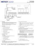
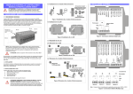
Gas Release Panel Short Form Installation Guide
Connecting the Standby Batteries
CAUTION: There is a risk of explosion if the battery is replaced by
an incorrect type. Always dispose of used batteries in accordance
with the battery manufacturers’ instructions.
Note: On a standard ‘as-supplied’ unit, PLK1 (‘Battery Monitoring’ link) is
not fitted and a fault will occur on initial power-up if fully charged batteries
are NOT connected. For the emergency standby power supply, only use
good quality, sealed VRLA batteries. Position and connect the 2x12Vdc,
7Ahr batteries, as shown in diagram (see right).
Connecting Circuits to the Main Control PCB
Terminate incoming and outgoing circuits at the Main Control PCB connectors (see Figure 2 overleaf).
Technical Specification
POWER SUPPLY
Mains Supply Voltage:
Internal Power Supply
Max. Output Current:
Power Rating (including charging):
Battery Type:
Battery charge Current:
Earth Fault Monitoring:
Mains supply/ Battery charger monitored for failure
Quiescent Current drain on mains fail
230Vac, 50/60 Hz
24Vdc Nominal
3A@230Vac
1.5A cont, 3A peak
2 x 12Vdc, 7Ahr VRLA type, connected in series
0.7A
YES
YES
40mA
DETECTOR CIRCUITS
Number of Conventional detector circuits:
Line Monitored for open and short circuit faults:
Max. Cable length per circuit:
Max. Number of smoke/heat detectors per circuit:
Max. Combined number of detectors and call points per circuit:
Zone quiescent current:
End-of-line resistor value:
3 @ 21-28Vdc
YES
250m
20
32
2mA max.
6K8 Ohm +/- 5%, 0.25W
SOUNDER CIRCUITS
Number of conventional sounder circuits:
Line monitored for open and short circuits:
Sounder output rating:
Max. Sounder cable length per circuit:
Max. Number of polarised sounders per circuit:
End-of-line resistor value:
3 (two x 1st stage, one x 2nd stage)
YES
21-28Vdc, fused @ 200mA per circuit
50m
10 @ 20mA each
6K8 Ohm +/- 5%, 0.25W
Item Numbers: 2983-0304
Introduction
The Gas Release panel is a three zone automatic extinguisher control panel that is compliant with EN12094-1
and EN54-2. The panel incorporates a 3A, EN54-4 compliant switch mode PSU and a 128 x 64 pixel LCD that
facilitates system programming.
Installation
Location
The panel must be mounted indoors on a dry, flat surface in an area that is well ventilated. Ideally the panel
indicators should be at eye level and the ambient light level should allow the status of any indicators to be clearly
seen.
Fixing
Note: The panel’s base PCBs should be removed prior to first fix installation.
Using the five mounting holes provided, fix the base securely onto a wall. The mounting holes are suitable for
use with No.8-10, or 4-5mm countersunk screws. Assess the condition and construction of the wall and use
suitable screw fixings. Any dust or swarf created during the fixing process must be kept out of the enclosure and
care must be taken not to damage any wiring or components.
Wiring and Cable Entry
All wiring should be installed in accordance with the current edition of the IEE Wiring
Regulations (BS7671), or the relevant national standards.
The requirement for the mains supply to the panel is fixed wiring, using 3-core cable (no
2
2
less than 1mm and no greater than 2.5mm ), or a suitable three conductor system, fed
from an isolating switched spur, fused at 3A.
In order to maintain cable segregation, the incoming mains cable should be fed into the
panel via the top right hand side knockouts (provided on the base unit). Knockouts
should be removed with a sharp, light tap using a flat 6mm broadsided screwdriver as
shown in diagram (see right). Always ensure that if a knockout is removed, the hole is
filled with a good quality 20mm cable gland. Any unused knockouts must be securely
blanked off.
WARNING: DO NOT ATTEMPT TO CONNECT THE MAINS SUPPLY TO THE POWER SUPPLY PCB UNTIL
ALL PCBs ARE SECURELY INSTALLED IN THE ENCLOSURE.
MONITORED INPUTS
Number of monitored inputs:
Thresholds:
End-of-line resistor value:
6 (Manual release, Flow switch, Low pressure, Mode, Hold, Abort)
8K to 2K ohms (normal); 1.8K to 200 ohms (active); 150 to 0 ohms (short circuit)
6K8 Ohm +/- 5%, 0.25W
Connecting Mains Supply to the Power Supply PCB
Terminate the mains cable at the Power Supply PCB connector CONN1 (see Figure 1 below).
AUXILIARY OUTPUTS
Number of auxiliary outputs*:
6 (Fire, Local fire, Extract, 1st stage, 2nd stage, Fault)
Extract time:
Adjustable 1-900 seconds (1 second steps)
Relay contact rating:
30Vdc, 1A max. Note: DO NOT switch mains voltage using these outputs
*Note; 5 Additional relay outputs (Reset, Mode, Discharged, Hold, Abort) are available on the GR Output Expansion Relay Board (Item No. 2980-0004)
REMOTE INPUTS
Number of remote inputs:
Auxiliary output:
4 (SIL, AL, FLT, RST)
24V, 100mA electronic fuse
EXTINGUISHANT RELEASE OUTPUTS
Extinguishant release output:
Extinguishant release time delay:
Extinguishant release duration:
Extinguishant release flooding time:
Extinguishant release end-of-line:
21-28Vdc, rated at 1A for 5 minutes
Adjustable 1-60 seconds (1 second steps)
Adjustable 1-300 seconds (1 second steps)
Adjustable 60-1800 seconds (1 second steps)
GR System Line Terminator (Item No. 2980-0005)
FUSES Compliant with IEC (EN60127 Pt2)
Mains supply fuse (F1): 1A HRC 20mm ceramic; Battery fuse (F2): 5A F 20mm glass; Auxiliary output fuse: 100mA electronic; Sounder circuit fuse: 200mA per
i it
DIMENSIONS
& WEIGHT
Physical Dimensions (W mm x H mm x D mm):
Weight:
Back box = 439 x 276 x 70 approx (Metal); Lid = 467 x 293 x 29 approx (Plastic)
1.75kg (without batteries)
Accessory Pack
1 x Installation Instructions; 1 x User Manual Log Book, 1 x Allen key; 1 x 1A HRC Fuse; 1 x 5A F Fuse; 1 x set of links for PLK1 & PLK2; 1 x set of battery
connection leads.
Figure 1 – Power Supply PCB Layout and Connection Details
Page 3 of 3
MAN1807
Website: www.ampac.net
“ Our aim is to provide ‘ Consistently Excellent Service ’ in the eyes of our customers ”
MAN1807
Page 1 of 3
Website: www.ampac.net
Revision: 29 July 2009
“ Our aim is to provide ‘ Consistently Excellent Service ’ in the eyes of our customers ”
Gas Release Panel Short Form Installation Guide
Item Numbers: 2983-0304
NOTES: See Technical Specifications overleaf for further details.
Z3
Z1
S1A
6K8 EOL
S2
S1B
Detector Circuits 1 to 3.
Sounder Circuits. Two x 1st stage; One x 2nd stage.
MON1
MON6
Monitored Input Circuits 1 to 6.
RLY1
RLY6
Relay Outputs 1 to 6.
6K8 EOL
Remote Inputs: +/- Remote Supply; SIL - Silence Alarm; AL - Sound Alarm; FLT - Fault; RST - Reset.
POLARISED
SOUNDER
+
DO NOT SPUR
WIRING NOT MONITORED
SMOKE OR
HEAT DETECTOR
RSU n (8 max)
MON6
DO NOT SPUR
WIRING NOT MONITORED
FLOW
SW
MON5
MON6
RSU 1
ESU n (8 MAX)
Z1
2
S1A
Z3
Z2
S2
S1B
ESU 1
MON1
MON2
MON3
MON4
-
ZONE 1
+
-
ZONE 2
+
-
ZONE 3
+
-
SOUND
1A
+
2
-
SOUND
1B
+
2
+
-
SOUND
2nd STAGE
2
-
MODE
SELECT
+
2
-
MANUAL
RELEASE
+
2
-
ABORT
+
2
-
HOLD
+
-
LOW
PRESSURE
+
-
FLOW
SWITCH
+
-
SIL AL FLT RST +
REMOTE INPUTS
2
-
A
RLY3
RLY4
RLY5
RLY6
RS485
B
A
B
REMOTE STATUS UNIT
C NO NO C NC NO C NC NO C NC NO C NC NO C NC
EXTRACT
GAS RELEASE PANEL MAIN CONTROL BOARD
Page 2 of 3
MAN1807
RLY2
Website: www.ampac.net
“ Our aim is to provide ‘ Consistently Excellent Service ’ in the eyes of our customers ”
1st STAGE
2nd STAGE
FAULT
LOCAL FIRE
FIRE
PRESS
SW
EXTINGUISHANT
ESU
+
2
RLY1
RESET SW
-
2
MON5
FAULT SW
+
2
0V
+24V
2
SOUND ALARM SW
2
SILENCE ALARM SW
2
SYSTEM LINE
TERMINATOR
SOLENOID
2
Relay 6 energises on activation of any zone fire alarm
or pressing panel sound alarm pushbutton
PRESSURE
SW
Relay 5 energises on activation of any zone fire alarm
or pressing panel sound alarm pushbutton
470R
Relay 4 is normally energised and de-energises upon
any fault condition
470R
Relay 3 energises when the panel has entered activated
condition, i.e. the extinguisher release timer has started
POLARISED
SOUNDER
Relay 2 energises on activation of a zone that is part of the extinguisher
release circuitry, or pressing the panel sound alarm pushbutton
+
SMOKE OR
HEAT DETECTOR
FLOW
SW
6K8 EOL
6K8 EOL
Relay 1 energises when an Access Level 2 user selects Start
Extract Fan after flooding time has elapsed (without a reset)
+
POLARISED
SOUNDER
+
-
EXTINGUISH ACCESS LEVEL
3 SWITCH
OUTPUT