1
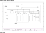
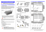
IR104 Relay / Optoisolator PC/104 Board User Manual
Revised 12-02
1. I/O ADDRESS SELECTION
IR104 occupies 8 addresses in I/O memory, of which 6 are used. The address is selected with
jumpers JP1 and JP2. The pins listed under each jumper block are the pins that must be shorted with
a jumper for the In position. On each jumper block, pin 1 is on the left and pin 3 is on the right. Note
that on JP1, pins 1 and 2 are used, but pin 3 is never used. On JP2, pins 2 and 3 are used, but pin 1
is never used.
Address
Hex
Decimal
JP1
pins 1 and 2
JP2
pins 2 and 3
240
576
Out
Out
260
608
Out
In
280
640
In
Out
300
768
In
In
2. I/O MAP
Base +
0
1
2
3
4
5
6
7
Write Function
Relays 1-8
Relays 9-16
Relays 17-20
------
Read Function
Read back value
Read back value
Read back value
-Opto inputs 1-8
Opto inputs 9-16
Opto inputs 17-20
--
3. REGISTER BIT ASSIGNMENTS
Addr
Operation
D7
D6
D5
D4
D3
D2
D1
D0
0
Read/Write
RLY8
RLY7
RLY6
RLY5
RLY4
RLY3
RLY2
RLY1
1
Read/Write
RLY16
RLY15
RLY14
RLY13
RLY12
RLY11
RLY10
RLY9
2
Read/Write
0
0
0
0
RLY20
RLY19
RLY18
RLY17
3
Not Used
4
Read only
IN8
IN7
IN6
IN5
IN4
IN3
IN2
IN1
5
Read only
IN16
IN15
IN14
IN13
IN12
IN11
IN10
IN9
6
Read only
0
0
0
0
IN20
IN19
IN18
IN17
7
Not Used
Definitions:
Rly1 – Rly20
In1 – In20
X
0
Relay outputs; 1 = on, 0 = 0ff
Optoisolator inputs; 1 = off, 0 = on
Bit not used
Bit reads back as a 0
IR104 programming information.doc
Diamond Systems Corp.
www.diamondsystems.com
4. I/O HEADER PINOUTS
Optocoupler inputs
Optocouplers are accessed through a 2x20 pin header CN3 at the top of the board. Pin 1 is on the left.
There is no difference between the A and B connection, since the inputs are not polarity sensitive.
In 1 A
In 2 A
In 3 A
In 4 A
In 5 A
In 6 A
In 7 A
In 8 A
In 9 A
In 10 A
In 11 A
In 12 A
In 13 A
In 14 A
In 15 A
In 16 A
In 17 A
In 18 A
In 19 A
In 20 A
1
3
5
7
9
11
13
15
17
19
21
23
25
27
29
31
33
35
37
39
2
4
6
8
10
12
14
16
18
20
22
24
26
28
30
32
34
36
38
40
In 1 B
In 2 B
In 3 B
In 4 B
In 5 B
In 6 B
In 7 B
In 8 B
In 9 B
In 10 B
In 11 B
In 12 B
In 13 B
In 14 B
In 15 B
In 16 B
In 17 B
In 18 B
In 19 B
In 20 B
Relay outputs
Realys are on 1x20 detachable screw terminal headers. CN1 on the left side of the board handles relays
1 – 10, while CN2 on the right side handles relays 11 – 20. The relay numbers are marked next to each
relay so you can identify each relay and its associated screw terminals. Pin 1 on both screw terminals is
the pin nearest the PC/104 connector, i.e. each terminal pinout is reversed with respect to the other. The
drawings below indicate the pinouts according to their actual board orientation. There is no difference
between the A and B connection, since the relays are not polarity sensitive. All connections are NO,
normally open.
CN1
Relay 10 B
Relay 10 A
Relay 9 B
Relay 9 A
Relay 8 B
Relay 8 A
Relay 7 B
Relay 7 A
Relay 6 B
Relay 6 A
Relay 5 B
Relay 5 A
Relay 4 B
Relay 4 A
Relay 3 B
Relay 3 A
Relay 2 B
Relay 2 A
Relay 1 B
Relay 1 A
20
19
18
17
16
15
14
13
12
11
10
9
8
7
6
5
4
3
2
1
IR104 programming information.doc
CN2
CN3 End
PC/104
Connector
End
20
19
18
17
16
15
14
13
12
11
10
9
8
7
6
5
4
3
2
1
Diamond Systems Corp.
Relay 20 B
Relay 20 A
Relay 19 B
Relay 19 A
Relay 18 B
Relay 18 A
Relay 17 B
Relay 17 A
Relay 16 B
Relay 16 A
Relay 15 B
Relay 15 A
Relay 14 B
Relay 14 A
Relay 13 B
Relay 13 A
Relay 12 B
Relay 12 A
Relay 11 B
Relay 11 A
www.diamondsystems.com
5. PROGRAMMING EXAMPLES
Example 1: Turn on a relay
Current state of relays 1 – 8 is relays 1-4 on, relays 5-8 off.
Turn relay 8 on:
Current data value at Base + 0 is 00001111 = 15
To turn on relay 8, we need to set bit 7 to 1.
Relay 8 = bit 7 = 10000000 = 128
New data value = 128 OR 15 = 143 (10001111)
Write 143 to Base + 0 to turn on relay 8 and keep relays 1-4 on, 5-7 off.
Example 2: Turn off a relay
Current state of relays 1 – 8 is relays 1-4 and 8 on, relays 5-7 off.
Turn relay 3 off:
Current data value at Base + 0 is 10001111 = 143
To turn off relay 3, we need to clear bit 2.
Relay 3 = bit 2 = 00000100 = 4
New data value = 143 AND NOT(4) = 139 (10001011)
Write 139 to Base + 0 to turn off relay 3 and keep relays 1, 2, 4, and 8 on, 5, 6, and 7 off.
IR104 programming information.doc
Diamond Systems Corp.
www.diamondsystems.com