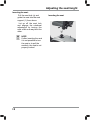
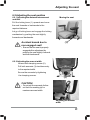
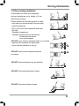
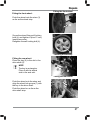
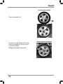
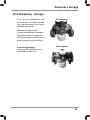
1
OPERATING MANUAL Super 6 ForU Introduction With the Super 6 ForU , you have now purchased a product which has been manufactured in accordance with the newest technical capabilities and based on the highest operating comfort. We have placed great value on the simplest possible operation and long service life in both construction and material selection. A large variety of useful accessories rounds off our range in addition to the ForU scooter. This Operating Manual assumes that the suitability of the user for scooter usage has been discussed with a doctor, therapist and/or dealer before operation. The operating manual will help you get to know the function of our ForU scooter and, in addition, describes • operation • care and maintenance • repair The manual has been drawn up using information available at the time of printing with regard to construction and operation of the scooter. We reserve the right to make changes due to technical improvements. If you have any other questions about this scooter please contact your retailer or supplier. 1 Contents 1.0 Safety instructions........................................................ 5 1.1 Symbols used ............................................................. 5 1.2 Intended use .............................................................. 5 1.3 General Information .................................................... 6 1.4 Safety when driving..................................................... 7 1.5 Safety during transport, assembly and maintenance ........ 8 1.6 Safety when handling batteries ..................................... 9 1.7 Safety - information about electronics............................ 9 2.0 Versions ........................................................................ 10 3.0 Extent of delivery.......................................................... 10 4.0 Components .................................................................. 11 4.1 The ForU ................................................................... 11 4.2 The dashboard - displays and controls .......................... 11 5.0 Brief instructions .......................................................... 12 5.1 Driving the ForU ......................................................... 12 5.2 Transporting the ForU ................................................. 14 6.0 Setting up the ForU ....................................................... 16 6.1 Adjusting the seat height ............................................ 16 6.2 Adjusting the seat position .......................................... 19 6.2.1 Adjusting the distance between seat and tiller............. 19 6.2.2 Adjusting the armrest width...................................... 19 6.3 Adjusting the tiller angle ............................................. 20 7.0 Information about safe ForU.driving ............................ 21 7.1 Driving up inclines and down slopes ............................. 22 7.2 Overcoming obstacles ................................................. 23 7.2.1 Driving Information – Overcoming kerbs .................... 24 7.3 Overload protection - motor protection ......................... 25 7.4 Battery charging state = driving range.......................... 26 7.4.1 Battery charging state.............................................. 26 7.4.2 Driving range .......................................................... 27 7.4.3 Overdischarge protection - battery protection ............. 27 8.0 Driving the ForU ........................................................... 28 8.1 Getting on and off ...................................................... 28 8.2 Turning the seat ......................................................... 30 8.3 Switching the ForU. On ............................................... 30 8.3.1 Operation indicator and fault display .......................... 30 8.4 Adjusting the speed .................................................... 31 8.5 Before driving ............................................................ 31 8.6 Driving.................................................................. ... 32 8.7 Using the motor brake ................................................ 32 2 Contents 8.8 Using the horn ......................................................... 33 8.9 Switching off / parking the ForU ................................. 33 9.0 Pushing the ForU ......................................................... 34 10.0 Attaching the shopping basket ................................... 34 11.0 Charging the batteries ................................................ 35 11.1 Charging the batteries ............................................. 36 11.1.1 Charging the batteries in the ForU via the tiller (22 Ah) .............................................................. 36 11.1.2 LED information at battery charger during charging .. 37 11.2 After charging ........................................................ 37 12.0 Things to know ........................................................... 38 12.1 The battery charger - functioning principle ................. 38 12.2 The Batteries .......................................................... 38 12.2.1 What are batteries for cyclic use? ........................... 39 12.2.2 When do the batteries achieve their maximum performance? ..................................................... 39 12.2.3 How do I make sure the batteries achieve their best service life? ................................................ 39 12.3 Anti tipping wheels .................................................. 39 12.4 Wheels and tyres .................................................... 39 12.5 The drive unit ......................................................... 40 12.6 The working principle .............................................. 40 12.7 The control unit ...................................................... 40 12.8 The auto switch-off ................................................. 41 12.9 Brakes on the ForU .................................................. 41 12.10 Driver´s licence .................................................... 41 12.11 Insurance ............................................................. 41 12.12 Approval for road traffic use ................................... 42 13.0 Transporting the ForU ................................................ 43 13.1 Transport information .............................................. 43 13.2 Transporting the complete scooter............................. 43 13.3 Preparation for transport - separating components ...... 43 13.3.1 Working step summary ......................................... 44 13.3.2 Removing the seat and rear panelling ..................... 44 13.3.3 Removing the battery case .................................... 44 13.3.4 Folding the tiller down .......................................... 45 13.3.5 Disengaging the drive unit from the chassis ............. 45 13.3.6 Installing step in the reverse order of removal ......... 45 14.0 Cleaning...................................................................... 46 3 Contents 15.0 Maintenance and Inspection ...................................... 47 15.1 Daily maintenance before start of journey .................. 47 15.2 Annual inspection - inspection timetable .................... 48 16.0 Troubleshooting ......................................................... 51 16.1 Before troubleshooting ............................................ 51 16.2 Troubleshooting ...................................................... 52 16.3 Operation indicator blink codes ................................. 54 16.3.1 Blink speed.......................................................... 54 17.0 Repairs ....................................................................... 55 17.1 Information about safety at work .............................. 55 17.2 Tools ..................................................................... 55 17.3 Wheels - removal and replacement ........................... 56 17.4 Replacing the wheel ................................................ 59 17.5 Fuses .................................................................... 60 17.6 Batteries ................................................................ 61 17.6.1 Disposal of used or damaged batteries .................... 61 17.6.2 Refitting battery cables ......................................... 62 18.0 Temporary storage ..................................................... 63 19.1 Specifications ............................................................. 64 19.1.1 General data ........................................................ 64 19.2 Torque for fixing screws ........................................... 65 19.3 Disposing of the scooter........................................... 65 20.0 Warranty information ................................................. 66 4 Safety instructions 1.0 Safety instructions 1.1 Symbols used This instruction manual contains the following symbols which are used to highlight special hazards in dealing with the product or information for simplifying the handling. NO Symbol mean 1 SERIAL NUMBER 2 DATE OF MANUFACTURE 3 MANUFACTURER 4 Direct current 24V 5 Protective earth (ground) 6 7 Caution In case of application as a safety sign, the rules according to ISO 3864-1 are to be adhered to. See safety sign ISO 7010-W001. Operating instructions 8 Security certificate symbol 9 The presence of this symbol indicates that the material used for the manufacture of specfic type of medical device, contains several phthalates mentioned with the symbol(DHEP,and/or DBP and/or BBP) The symbol of the crossed out wheeled bin indicates that the product (electrical and electronic equipment) should not be placed in municipal waste. Please check local regulations for disposal of electronic products. 10 1.2 Intended use The KYMCO Healthcare scooter is constructed for use both indoors (Suggest general use - indoors) and outdoors . 5 Safety instructions It is intended to increase the mobility of persons who are both physically and mentally capable of assessing any driving situations correctly and reacting correspondingly to them at any time. The Super 6 models are classified as an “invalid carriage” for use indoors, on pavements, footpaths, pedestrian zones and areas free from motor traffic. They must not be driven on public roads with the exception of crossing or when no pavements are available. 1.3 General Information Read the entire operating manual thoroughly before using the Super 6 ForU! Ensure that: •The operating manual is read by all people who drive, care for and service the scooter. •All persons who drive, care for, service or repair the scooter have access to the operating manual at any time. Any damages resulting from nonobservance of this operating manual are excluded from the guarantee. Risk of accidents! • Do NOT use the scooter if your driving capability is impaired through consumption of medicine or alcohol. • Only use the scooter for its correct intended use. • Only use the scooter when it is in perfect working order. • If any breakdowns occur, stop using the scooter immediately and secure it against unauthorized use. • It is imperative that you always rectify any faults which could influence the function and safety of the scooter immediately. • Observe maximum loading = see Specifications • Only use accessories and spare parts authorized by KYMCO Healthcare UK Limited. • The scooter is only authorized for transport of one person. • Do not carry out any seat adjustments while driving. 6 Safety instructions Tipping hazard! • Do not adjust the seat if the scooter is standing on an incline. • Do not lean out over the armrest to the sides or over the backrest to the rear. 1.4 Safety when driving Risk of accidents! • Check correct functioning of the brakes before every journey. • Check the tyre air pressure regularly. • Always use the seat belts when driving. • Do not switch the scooter off while driving. • Do not drive up or down gradients which are too steep, over obstacles on gradients or up and down ramps. Observe maximum climb angle = see Specifications • Only drive through restricted widths, around bends, inclines and ramps with reduced suitable speed. • Only drive up or down inclines when the backrest has been adjusted to vertical. • Don´t drive too close to open waters. Tipping hazard! • Do not carry out any seat adjustments while driving. • Only drive over obstacles and up kerbstones at the lowest point and at right angles. • Avoid sudden changes of direction and speed. • Avoid steep gradients where there is a danger of skidding (ice, snow, wet surfaces etc.). • Avoid loose surfaces whose characteristics you are not able to assess (woodlands, turf, beaches, gravel etc.) • Always drive straight up and down gradients - do not drive in zigzags. • Do not turn around on inclines. • Do not drive down steps. • Do not drive backwards down gradients, stairs or kerbstones, or over obstacles. 7 Safety instructions Danger due to unintentional movement! • Always turn the scooter off using the keyswitch if you: - want to get on or off - intend to stop for long periods - are putting the scooter away. 1.5 Safety during transport, assembly and maintenance If the scooter is transported in the vehicle when fully assembled: - no persons may sit on the scooter during loading! - no persons may sit on the scooter during transport! Clamping and crushing hazard! Increased hazards due to clamping or crushing result due to the high component weight (such as batteries) during preparation for transport and maintenance work. • Always carry out any work to be done with great care. • Always try to get help from a second person, especially when stowing parts for transport. • Only carry out any work described if you are used to working with the tools required. • Only carry out work using suitable too Injury hazard due to improper assembly! • Ensure that all components in the Scooter have been correctly assembled. • After assembly, check that all locking devices are holding correctly. Accident hazard due to incorrectly bolted connections! • If bolted connections have self-locking nuts, ensure that these are replaced when reassembling. • Do not replace self-locking nuts with normal nuts. • If bolted connections have lock washers, check lock washers when reassembling and replace if necessary. 8 Safety instructions 1.6 Safety when handling batteries Fire hazard! • Do not cover the battery charger and ventilation slot while charging batteries. • Only use the battery charger in well-ventilated areas. Risk of accidents! • Only use the original battery charger (included in delivery). • Let your dealer replace your battery. • Only use batteries as detailed in the chapter entitled “Specifications”. • Observe warning information given by the battery manufacturer. • Batteries are extremely heavy. Burn hazard due to damaged batteries! Batteries discharging acid can lead to serious burns. • Do not touch damaged batteries with your bare hands. Use rubber gloves! • If acid should contact your skin, wash the affected area immediately with plenty of water and contact a doctor. • If acid should come in contact with your eyes, rinse them out immediately with lots of water and visit a doctor. • Always change any clothing soiled with battery acid immediately. 1.7 Safety - information about electronics Accident hazard due to failures! Radio, television, radio transmission devices and mobile phones produce electromagnetic fields. These can negatively influence the scooter electronics functions. • Do not drive close to strong radio or television transmitters (transmitter masts). • Switch the scooter off if you are using your mobile phone. Interference caused to other devices! The scooter produces an electromagnetic field which can negatively affect functioning of electrical devices such as medicinal devices, radio receivers or mobile telephones within the vicinity. 9 Versions 2.0 Versions 3.0 Extent of delivery After receiving your ForU scooter, please check the following: •That the delivery is complete in accordance with the list below •Tthe delivery condition using the inspection plan (chapter 14.2) If any faults are apparent or components are missing, please contact your supplier or dealer. The following items are included in delivery in addition to the scooter: 1. Shopping basket 2. Two vehicle keys for switching the on/off 3. Battery charger 4. Operating Manual 10 Components 4.0 Components 4.1 The ForU Dashboard with controls Seat unit with head and armrests Shopping basket Indicators and position light Indicators and position light Steering wheel Anti tipper Tiller 4.2 The dashboard - displays and controls Operation indicator(fault display) Battery charge display Speed controller Indicator switch Headlight switch Charging socket Key switch Drive lever (reverse) Drive lever (forward) Horn Hazard H/ L speed switch 11 Brief instructions 5.0 Brief instructions The following brief instructions should enable people to quickly get used to operating the scooter after a long period of non-use and to refresh existing knowledge of operation. It is imperative that you follow the instructions given in the main manual! 5.1 Driving the scooter NOTE Before starting driving, adjust the seat height, the backrest and the armrests to a comfortable position. Your specialist dealer would be very glad to help. 1.) Turn the seat to the outside. 3.) Switch on the scooter 12 2.) Get in - turn the seat in the direction of travel Brief instructions 4.) Check the battery charging state 5.) Set the maximum speed Red-reserve Yellow-medium Green-full = lowest possible driving speed (approx. 4mph) = highest possible driving speed (approx. 6mph) 6.) Driving Operate the drive lever slowly until the required speed has been reached The drive lever position controls the speed variably right up to maximum driving speed. 1 Standstill (brake engaged) Standstill (brake engaged) Reverse 7.) Braking = release drive lever (1) (1) Forwards 8.) Horn 9.) Hazard 10)Position light (8) (9) (10) 13 Brief instructions 5.2 Transporting the scooter Dismantling the scooter (stages 1 to 9) 1.) Remove the seat 2.) Removing the rear panelling 3.) Remove the lighting cable 4.) Remove the battery plug and front connector 5.) Remove the battery belts 6.) Fold the tiller down and batteries 14 Brief instructions 7.) Unlock the drive unit 8.) Tilt the drive unit away 9.) Remove the chassis Step Step Step Reassembling the scooter (Stages 9 to 1) The scooter dismantled: 1. Chassis 2. Batteries 3. Drive unit 4. Rear paneling 5. Seat unit 15 Adjusting the seat height 6.0 Setting up the scooter The following passage describes how to set up your scooter in order to ensure that you have a comfortable and safe drive. 6.1 Adjusting the seat height NOTE! The seat must be removed from the scooter in order to adjust the seat height. You should try to get help from a second person if possible or contact your dealer. Removing the seat: Tilt the backrest forwards. Removing the seat Lift the seat while pulling the seat lock (a) out of the seat support (1). (1) Adjusting the seat height: Remove the clamping bolt (1) and hold bolt.(2) Out of the seat support (3). 1xRing spanner, size 12 mm 1x Hexagon bolt. 16 (a) Removing the clamping bolt and hold bolt Adjusting the seat height In order to avoid danger when driving. Please adjust the height of seat, and then confirm if the seat’s bolt is at the right position, otherwise, the seat would be shaked. The seat height (h) is adjusted using the five holes (1-4) in the seat support. h 4 holes Pull the seat support (4) out as far as the required height until the correct hole (1-4) appears in the seat tube hole (5). Push the clamping bolts (6) into the seat tube from the front. 17 Adjusting the seat height Inserting the seat: Pull the seat lock (a) and guide the seat into the seat support (1) from above. Let go off the seat lock and engage the rotational adjustment by turning the seat a little one way then the other. NOTE If after inserting the seat it is not possible to turn the seat or to pull the seatlock, the seat is not properly locked. 18 Inserting the seat (a) (1) Adjusting the seat 6.2 Adjusting the seat position 6.2.1 Adjusting the distance between seat and tiller Moving the seat Pull the locking lever (1) upwards and move the seat forwards or backwards to the required distance. Let go of locking lever and engage the locking mechanism by pushing the seat slightly forwards and backwards. Accident hazard due to non-engaged seat! (1) • Ensure that the seat is properly engaged after adjustment by pushing the seat slightly forwards and then backwards. 6.2.2 Adjusting the armrest width Loosen both clamping screws (2). Pull both armrests (3) simultaneously (3) to the required width. Secure the armrests by tightening the clamping screws. (2) CAUTION! • Do not pull the armrests further out than the marking (a) for maximum armrest width. (a) Adjusting the armrest width 19 Adjusting the seat 6.3 Adjusting the tiller angle adjusting the tiller Always adjust the tiller so that you can reach all displays and controls easily at any time. The tiller can be variably adjusted. Turn and loose the locking lever(1) Pull the tiller for backwards into the required position . Tighten the locking lever . Ensure that the tiller is engaged properly by moving slightly forwards and backwards. Accident hazard due to non-engaged tiller! • Ensure that the tiller is properly engaged after adjustment by pushing it slightly forwards and then backwards. 20 (1) Driving information 7.0 Information about safe d r iving Always carry out the safety information described in chapter 1.4 “Safety when driving“! Driving is very simple and after a few practice sessions you will Find it very easy. The following information should help you to drive safely through traffic: •always match your speed to the driving situation in which you find yourself. •always reduce the speed when you are driving through: - unclear areas - narrow gaps - tight curves - inclines - ramps •take a trial run with your scooter in an area with no pedestrians, or in a closed-off area. •always steer the scooter using both hands on the handlebars.always keep •your feet in the foot area while driving . 21 Driving information 7.1 Driving up inclines and down slopes The scooter will slow down to a safe reduced speed to protect the motor if in overload/ over heated conditions. Please switch off and allow the motor to cool down before continuing your journey. You may need to choose an alternative more suitable route if overload trip re-occurs. Climb angle examples: a 1 metre long ramp should not be higher than. 18 cm a 2 metre long ramp should not be higher than. 36 cm • Avoid driving across an incline (always try to drive in the direction of the incline / decline). Tipping hazard! There is an increased danger of tipping when climbing or descending gradients if: • the scooter is loaded at the back and additionally the seat has been adjusted to its rear position. You can achieve increased tipping safety if: • you adjust the seat in a more forward position. • you lean your upper body slightly forwards (see sketch). 22 Increased tipping safety Driving information The scooter can climb over obstacles without any problem. Please observe the following points to make sure that your scooter doesn’t tip over while climbing obstacles: 8 6 cm such as kerbstones up to height of 8 cm 8 6 cm 7.2 Overcoming obstacles • Don’t try to drive over obstacles which are too high Example: kerbstones Remedy: always climb up kerbstones at lowered entry areas such as driveways. •DO NOT try to climb an obstacle when on an incline. • approach the obstacle at a right angle • try to clear the obstacle in one go. •DO NOT drive over the obstacle with just one wheel. •DO NOT drive backwards over an obstacle. •DO NOT drive backwards down a kerb. •DO NOT drive down stairs or steps. 23 Driving information 7.2.1 Driving Information – Overcoming kerbs Risk of accidents! Neogating kerbs needs some practice. • Please observe the maximum obstacle hights of 8 cm. • Please start practicing kerb climbing with small kerbs. Approach at a right angle Approach the kerb at a right angle. Stop in front of the kerb Stop approximately 0.5 Meter / 19 inches in front of the kerb. Adjust the speedcontroller Adjust the speed controller to maximum speed. Press the drive lever fully forward and try to clear the kerb in one go. The speed of the scooter should only be at 1 mph when the front wheels hit the kerb. Keep the drive lever in the fully forwards position until the rear wheels have cleared the kerb. 24 Overcome kerb Driving information 7.3 Overload protection - motor protection The overload protection switches the drive off if the motor becomes overloaded by trying to climb over too high an obstacle such as a kerbstone, or if you try to climb too steep of an incline. If the motor is overloaded, the following happens: • the scooter becomes noticeably slower and then stops • the control system switches the scooter off To rectify this: Switch the scooter off and allow it to cool down for a few minutes. Switch the scooter on again and •Reverse away from the obstacle (such as kerbstone) and then try again at a lower point. •Be careful turning the scooter around on inclines, and always reverse away very slowly. Tipping hazard! There is an increased tipping hazard if the incline is very steep. • Try to get help from a second person when turning your scooter around. Accident hazard in push mode! If the incline is too steep, there is a danger that you will not be able to hold into the scooter and that it will roll down the incline uncontrolled. • Try to get help from a second person when turning your scooter around. 25 Driving information 7.4 Battery charging state = driving range 7.4.1 Battery charging state Battery charge display Battery charge display: The battery charger display on the dashboard shows the battery charging state. Full = maximum range Medium = decreased driving range, charge batteries after journey Reserve = minimum driving range, end Display ranges Red-reserve Yellow-medium Green-full journey as soon as possible, charge batteries Important information about reading the battery charge display: •If the scooter is at standstill, it is often the case that the battery charging state is shown higher than it actually is. •The display can vary greatly while the vehicle is travelling (depending on load). •If the vehicle is under heavier loading (for example heavy acceleration, driving up hills), the pointer can sometimes go to the red area of the display. This is not critical and does not indicate the actual charging state of the batteries. •If the pointer has gone into the red area of the display after the journey, it will often show green after the scooter has been turned off for a long period. This does not indicate the actual charging state of the batteries! If the pointer is in the red area of the display at the end of the journey, the batteries must be charged before continuing the journey. Disregarding this can lead to destruction of the batteries! Determining the actual charging state: Drive at a constant speed for about 200 m along a straight level route. The value shown by the display during the journey is the actual battery charging state. 26 Driving information 7.4.2 Driving range The driving range is dependent on the following conditions in addition to battery charge: - landscape conditions (level or steep) - weight of user - weather conditions (cold, rain) - driving with headlights (if fitted) For this reason, information about the driving range is only given as a guideline. The more experienced you are in using scooter, the easier it will be for you to determine the driving range using the battery charging state. You will be able to achieve the best possible driving range if you: • ensure that the tyres are inflated correctly • avoid steep inclines as much as possible • do not carry any unnecessary luggage • drive at an even speed • do not accelerate or brake unnecessarily. The driving range will be decreased if you: • drive with headlights • drive in cold weather • drive in hilly regions NOTE please see the information about batteries in the Appendix. 7.4.3 Overdischarge protection - battery protection In order to protect the batteries from over-discharging, the control unit switches off. This takes place when the battery voltage falls below 17 Volts. Display: Battery charge The battery charger display pointer is pointing to display the left at the end of the red area. To rectify this: You must not drive any longer! Connect the Scooter to the battery charger and charge the batteries for at least 12 hours. NOTE If the battery voltage falls below 16 Volts, the batteries can no longer be charged with the battery charger supplied. In this case you must contact your dealer. 27 Driving 8.0 Driving 8.1 Getting on and off Please observe the following before getting on or off: •The scooter must be standing on firm, level and non-slippery ground. •The engaging lever for push mode must be in the drive position (see chapt.9.0) •Turn off and remove the key. •Tilt the steering column Turning the seat forwards (see chap. 6.3) •When getting in and out, ensure that your clothing does not get caught on the drive lever. After you have got onto the scooter, pull the seat lock (1) forwards again, turn the seat to face the direction of travel (4) and engage. Accident hazard due to non-engaged seat! Getting on • Ensure that the seat is properly engaged after getting on by turning the seat slightly left and right. 28 Driving NOTE! • If you feel you are safe enough, you can of course get onto the scooter without turning the seat round. • You can lift up the armrest on the side where you are standing and then get on. 29 Driving 0° 8.2 Turning the seat The seat can be turned to both sides of the angle, and firmly engaged in 8 positions (each position turns 45°). 45° 135° 45° 90° 135° Turning the seat: Pull the turning lock (1), turn the seat in the required direction or position (2) and engage. Accident hazard due to incorrect seat position! • Always turn the seat to face forwards and engage it before driving. If the seat has been turned, the possibility of tipping is increased. • Before turning the seat, always ensure that the scooter is on an even and solid surface. Switching on 8.3 Switching on The switch is located on the dashboard. Insert the key into the switch and turn it to the right to switch on. 8.3.1 Operation indicator and fault display This light shows that the scooter is switched on and ready for driving. It also displays any errors in the scooter electronics and electrical system. Fault display takes place using different blinking speeds or blink sequences. You can find more information in the chapter entitled “Troubleshooting”. 30 90° Operation indicator 180° Driving 8.4 Adjusting the speed Your maximum driving speed can be variably adjusted using the speed controller. Maximum driving speed = drive lever pressed as far as stop Controller symbols: = lowest possible maximum driving speed (approx.4mph) = highest possible maximum driving speed (approx. 6 mph) Speed controller Adjust the required maximum driving speed by turning the speed controller. NOTE Use the controller to adjust the speed to suit local conditions. Select a lower speed if you are driving through narrow gaps, on inclines or through crowds. 8.5 Before driving Checks before driving: •Are the batteries charged? Check the display! To check, drive slowly •Are the brakes working? and stop again! in working order! in working order! •Are the tyres and wheels undamaged and is the air pressure correct? Visual check of tyres and wheels! in working order! •Is the tiller locking Observe chapter 13.3.4 ! in working order! Only start driving if everything is in working order! Get defects repaired immediately. 31 Driving 8.6 Driving Accident hazard due to locked tiller! • Before driving off, turn the tiller to check that it is not locked. Observe chapter 13.3.4. Hold the tiller firmly in both hands. Press the drive lever (1) in the direction of travel until the required speed has been reached. Handle Handle = driving forwards = driving in reverse The drive lever position controls the speed variably right up to maximum driving speed. Standstill (brake engaged) Standstill (brake engaged) 1 Reverse 8.7 Using the motor brake Forwards Motor brake Let go of the drive lever (1). The drive lever stops in the central position the scooter uses the motor to brake. Emergency braking = let go of the drive lever! The drive lever automatically returns to the central position if you let go. The FOR U automatically brakes using the motor. 32 Driving 8.8 Using the horn Using the horn Press the horn button (5). It will sound for as long as you hold the button down. 8.9 Switching off / parking Switching off •Turn the key to the left to switch off. Always turn off using the key switch if you: • want to get on or off. • intend to stop for long periods. Always remove the key from the key switch if you: • want to park and get off. 33 Pushing Disengaging the drive 9.0 Pushing In order to be able to push the scooter you must disengage the drive motor. The disengaging lever (1) is located on the right-hand side of the scooter No one is permitted to sit on the scooter When it is being pushed. = Pushing (a): Switch off. Push the disengaging lever (1) forwards as far as the stop (limit position). =Driving (b): Pull the disengaging lever (1) to the rear as far as the stop (limit position). NOTES • Always switch off to push it. • If a pre-set speed is exceeded while you are pushing , the drive motor will switch on automatically and brake the scooter. Risk of accidents! • Do not pull the disengaging lever while driving. • Never switch to push mode when somebody is sitting on the scooter. • The engaging lever always needs to engage securely at the limit position. • Do not disengage the motor when on an incline. 10.0 Attaching the shopping basket Push the shopping basket(1)from above into the basket holder receptacles (2) on the tiller. NOTE Use the shopping basket only for s mall loading. 34 Charging the batteries 11.0 charging the batteries Please also see the information given in the chapter entitled “Things to know“. Charging information: •The surrounding temperature should be between 10° and 30° Celsius. •The charging time will increase at lower temperatures. •Only use the original battery charger (included in delivery). •Only use the battery charger in a dry and well-ventilated room. •Do not cover the battery charger and ventilation slot while charging batteries. •The battery charger has an automatic switch-off device which prevents overcharging the batteries. Do not leave the battery charger connected to the scooter for more than 24 hours. - The batteries can be charged overnight. •Switch the scooter off before charging the batteries. When is charging required? •The battery charge display is in the red area •After the final journey of the day •At least once per week Charging times: Between 8 and 14 hours depending on current battery charge state. NOTE The battery charger is designed to be able to charge completely discharged batteries within eight hours to 80% of their capacity. 35 Charging the batteries 11.1 Charging the batteries 11.1.1 Charging the batteries via the tiller Switching off OFF Switch off. Engage the engaging lever for push mode into the “drive“ position. It is imperative that you observe the sequence for connecting and disconnecting the battery charger. The jack socket (3) for connecting the battery charger is located on the tiller. Engaging Connecting the battery charger (1.) Connect the battery charger plug (4)to the charging socket. (2.) Connect the battery charger mains plug (5) to a mains socket and switch on. NOTE: The battery charger switches on automatically when connected to the mains. 36 Charging the batteries 11.1.2 LED information at battery charger during charging LED -> Color-> Meaning LED (a)-> Red-> battery charger -> Orange -> charging in progress (a) -> Green-> charging complete, 11.2 After charging 1.) Switch off and remove the battery charger plug from the mains socket. Removing the mains plug Removing the battery charger (2.) Pull the battery charger jackplug out of the jack socket. . WARNING The use of the coupler and detachable powercord plug isolates from the main power. It is not to be used with other equipment, this will result in the equipment being difficult to use. 37 Things to know 12.0 Things to know 12.1 The battery charger - functioning principle The battery charger regulates the voltage (Volt) and the current (Ampere) from your mains connection down to the voltage required for charging your batteries (24 Volt). The amount of charging current required is dependent on the charging state of the discharged batteries. Batteries mostly discharged = more charging current Batteries half discharged = decreased charging current Batteries completely charged = no charging current Since no charging current is flowing when the batteries are full, the batteries cannot be overloaded. 12.2 The Batteries The entire power supply is taken over by two 12 V batteries. These are located below the motor cover under the seat. The batteries used in the scooter are known as batteries for cyclic use. Only enclosed maintenance-free batteries are used. 38 Things to know 12.2.1 What are batteries for cyclic use? Batteries for cyclic use are designed, in contrast to starter batteries as used in cars, so that they deliver continuous energy over a longer period of time and allow a considerable number of charging phases. 12.2.2 When do the batteries achieve their maximum performance? Fixed cycle batteries achieve a maximum performance after four or five charging and discharging cycles. Only at this point is their internal chemical equilibrium achieved so that they can produce maximum performance and service life. 12.2.3 How do I make sure the batteries achieve their best service life? •Always charge your batteries completely after use. •Charge your batteries regularly. •Only store completely charged batteries in the vehicle. Anti tipping wheels 12.3 Anti tipping wheels The anti tipping wheels (1) reduce the danger of tipping during extreme manoeuvres when fixed to the rear of the scooter. It is not permitted to drive the scooter without anti tipping wheels. Wheels and tyres 12.4 Wheels and tyres The Super 6 is fitted with 260 x 85(solid tyres) 39 Things to know Drive unit 12.5 The drive unit The complete drive unit is located in the rear of the scooter and consists of the following main components: • the batteries(1) • the drive motor with rear axle (2) • the control unit (3) 12.6 The working principle The drive consists of the drive motor, the gearbox and the rear axle. Drive takes place from the drive motor via the gearbox and rear axle to the rear wheels . 12.7 The control unit The control unit is a programmable electronic regulating unit. It regulates drive characteristics such as acceleration, maximum speed and braking behaviour. The drive characteristics can be set to match the user’s requirements by altering the programming. Reprogramming may only be carried out by specialist dealers. 40 Things to know 12.8 The auto switch-off The auto switch-off automatically switches the scooter off after 10 minutes at a stand- still. This protects the batteries from being discharged if the ForU was inadvertently not switched off. 12.9 Brakes The scooter is automatically braked if the drive lever (1) is in the central position. To apply the brakes, simply let go off the drive lever which is then returned to its central position by a spring. The scooter is then braked by the drive motor. When the scooter is at a standstill or has been switched off, it is braked by a magnetic brake. Drive lever 12.10 Driver´s licence Not required! 12.11 Insurance As a scooter user you must be aware of the risks involved to both yourself and others. It is recommended that you take out third party insurance to cover you against any possible claims. Advice and policies are available from insurance companies or alternatively ask your scooter supplier for details. 41 Things to know 12.2 Approval for road traffic use Super 6 ForU models are not defined as motor vehicles, but are a Class 2 Type invalid carriage. This type of scooter is for use on pavements and pedestrian areas with the exception of crossing roads. Use on public roads only permissible when no pavement is available. WARNING Equipment in a power interruption will cause a malfunction which can be dangerous. 1. Turn off the charger switch 2. Wait for the power to return, turn on the charger switch. WARNING Improper installation or use of these accessories, or scooter modification, will void the scooter warranty. This can negatively affect performance, and can even be illegal. 42 Transporting the scooter 13.0 Transporting the scooter 13.1 Transport information Depending on the size of the transport vehicle, the scooter can be dismantled in a few steps so that it can also be easily transported in smaller vehicles. When transporting, take particular care to ensure that the batteries are securely fastened and make sure components cannot tip over. No liability can be accepted for damage caused by transportation. 13.2 Transporting the complete scooter No persons are permitted to sit on the scooter during loading! No persons are permitted to sit on the scooter during transport! Drive or push the scooter up a ramp into the vehicle. Switch the engaging lever to drive mode. ‘ Secure the scooter against tipping over by fastening it to the transport vehicle with transport straps. 13.3 Preparation for transport - separating components Clamping and crushing hazard! Increased hazards due to clamping or crushing result due to the high component weight (such as batteries) during preparation for transport. • Always carry out any work to be done with great care. • Always try to get help from a second person, especially when stowing parts for transport. 43 Transporting the scooter In just a few steps you can dismantle the scooter down to the following components to make it ready for transport: 1. Chassis 2. Batteries 3. Drive unit 4. Rear panelling 5. Seat unit 13.3.1 Working step summary 1. Remove the seat unit. 2. Remove the rear panelling. 3. Remove the batteries. 4. Fold the tiller down. 4. Disengage the drive unit from the chassis. 13.3.2 Removing the seat and rear panelling Tilt the seat backrest forwards. Lift the seat while pulling the seat lock (a)out of the seat support (1). Pull the rear panelling(b) off the scooter upwards. 13.3.3 Removing the batteries Press the locking device on the plug and disconnect connecting plugs on the cable. Remove the battery belts. Remove the batteries. 44 (a) (1) (b) Transporting the scooter 13.3.4 Folding the tiller down Folding the tiller down Pull the locking lever(1) and fold the tiller to the rear (2) until it is horizontal. (1) 13.3.5 Disengaging the drive unit from the chassis (a) Separate the front unit connecting plug. (b) Open the clamping bolt camping lever and fold the clamming bolt upwards. (c) The drive unit to the rear onto the anti tip wheels. (d)Remove the frames upwards from the holding bolts on the drive unit. (2) 13.3.6 Installing step in the reverse order of removal. (see chapt.5.2) 45 Cleaning 14.0 Cleaning NOTE • Only use mild detergents without scouring agents to clean any surfaces. • Please observe instructions for use on the detergents to avoid damage to the component surfaces. • Do not use any sharp-edged tools such as knives, metal scrapers or aggressive solvents for cleaning. • Do not use high-pressure cleaners to clean the scooters. • Never direct water spray onto the fittings on the tiller or drive unit components. Light soiling or dust is best removed using soft cloths. Heavy soiling can best be removed with damp cloths and slightly soapy water. Use a dry cloth to dry the scooter off after cleaning! All lacquered surfaces can be cleaned and preserved using car polish. 46 Maintenance and Inspection 15.0 Maintenance and Inspection If you find any faults on your scooter during maintenance which are not covered by the repair information, please contact your dealer. Always remove faulty scooters from operation and secure them against unauthorized use (remove key). 15.1 Daily maintenance before start of journey Check the brakes by driving slowly and then braking. Make a visual check of wheels and tyres for damage. 47 Maintenance and Inspection 15.2 Annual inspection - inspection timetable Take your scooter once per year to your dealer for an inspection. He will have the necessary tools and experience to service your scooter correctly. Description (Component / inspection for) Assessment OK Defective Component : Seat Seatbelt / no damage fixed securely can be easily adjusted closed securely Armrest padding / no damage, fixed securely Armrest, folding mechanism / no play in joint functions easily Armrests, width adjustment / no damage functions easily Backrest upholstery / no damage fixed securely Backrest adjustment / no play in joint functions easily Seat upholstery / no damage fixed securely Seat and back frames / no damage Seat support - chassis connection / no damage, no play in connection 48 Maintenance and Inspection Description (Component / inspection for) Assessment OK Defective Component : Tiller Panelling / no damage fixed securely Grip rubbers / no damage fixed securely Tiller, folding mechanism / no play in joint functions easily Component : chassis Connections / no damage Frames / no damage no corrosion Reflectors / no damage Steering mechanism / no damage no play in joint functions easily Wheels / no damage fixed securely Tyres / no damage Antitipper wheels / no damage rollers turn easily 49 Maintenance and Inspection Description (Component / inspection for) Assessment OK Defective Component : Displays and controls, electric system, electronic system Drive lever/ No damage Easy functioning over the entire lever movement Returns to central position after releasing from any position Secure blockage of magnetic brakes when lever is in central position ( scooter can not be pushed) Dashboard switches / no damage safe function Dashboard displays / no damage safe function Indicator lamps / no damage safe function Charger jack socket / no damage Batteries / no damage fixed securely Check battery voltage (12-14 Volt per battery) Check battery capacity Control unit / no damage fixed securely Cables and connecting plugs / no damage fixed securely 50 Maintenance and Inspection Description (Component / inspection for) Assessment OK Defective Component : Drive Motor, drive / no damage fixed securely drive noise Motor, magnetic brake / holding force OK (Scooter can not be pushed with engaging lever in driveposition) Engaging lever / no damage functions easily lever engaged (lever remains engaged) 16.0 Troubleshooting 16.1 Before troubleshooting Before you start troubleshooting, please observe the following points to avoid simple error sources. Switch off. Ensure that the main plug (1) and the battery plug(2) for a tight fit. Switch on again. If the error should occur again, you can find information about troubleshooting and appropriate remedies in the lists in sections 16.2 and 16.3. 51 Troubleshooting 16.2 Troubleshooting Fault Cause Remedy Scooter does not run / no display at the dashboard Scooter not switched on Switch the scooter on (chapter 8) Power supply interrupted Battery not pluged in Front unit connector not plugged in Check the battery fuses (chapter 17) Check fuse in power supply to tiller head (chapter 17) Scooter does not run Batteries discharged Charge the batteries (chapter 10) Batteries batteries defective Replace (dealer) Check battery charge display Charge the batteries (chapter 10) (battery discharged). switched to push mode Switch to drive mode (chapter 9) Drive lever drive lever pressed Release while switching on Fault on drive lever Visit your dealer Automatic switchSwitch scooter off off (overload and switch scooter off protection) active on again a few seconds later for the unit to reset. Operation indicator blinking 52 Check blink code (chapter 16) Troubleshooting Fault Cause Main fuses blow frequently Batteries defective Remedy Motor defective Fault in control unit Visit your dealer Short-circuit in electrical equipment Battery charge display moves rapidly to discharged during journey Motor jerks during driving Batteries do not charge Batteries discharged Charge the batteries (chapter 10) Batteries defective Motor defective Visit your dealer Defective fuse in power supply to tiller head Visit your dealer Defective fuse in battery cable Visit your dealer Front unit connector not plugged in Plug in front unit connector (chapter 13) Battery charger defective Batteries completely discharged Visit your dealer 53 Troubleshooting 16.3 Operation indicator blink codes The operation indicator (1) on the dashboard is also designed as a display for error messages. Various faults in the drive electronics are displayed using blink sequence is as listed. 16.3.1 Blink list Instrument indicator Error code 002,003 0203,0204 0810,0814~17 1000 LED indicator slight blink 8xblink 8xblink 7xblink blinking quickly 1400 1500~1502 1600 1705 1802 1805 1B20 1D02 3xblink 9xblink 10xblink 8xblink 8xblink 8xblink 7xblink 1E03 6xblink 2102 2C00,2C01 2D01 3100,3102 3210,3213 3600~360E 3B01 4401 7000~7001 54 8xblink 1xblink continue slowly 8xblink 8xblink 8xblink 8xblink 2xblink 8xblink 4xblink Cause Auto switch off(scooter stay 10min ),KEY-ON again Fault in ECU or wires fall off Fault in ECU or wires fall off Fault in drive lever, Lever does not reset Charging the scooter, scooter does not run Fault to motor brake or wires fall off Fault to motor brake Battery voltage too low Fault in ECU or wires fall off Fault in ECU or wires fall off Fault in ECU or wires fall off Fault in drive lever, Lever does not reset Charging the scooter, scooter doesn't run Fault in ECU or wires fall off Batteries voltage too low Fault in ECU or wires fall off Fault in ECU or wires fall off Fault in ECU or wires fall off Fault in ECU or wires fall off Motor cable short-circuited Wires fall off Parking brake off Repairs 17.0 Repairs The following repair information should enable you to carry out small repairs on your vehicle yourself. You should, however, only carry out such work if you are used to working with the tools described here since it is impossible to fully prevent injury hazards when handling tools. If you are not sure, you should try to get help from a second person if possible or contact your dealer. In order to guarantee that all nuts and fixing screws are fitted tightly after repairs, you should ensure that these are tightened using the torque specified. 17.1 Information about safety at work Clamping and crushing hazard! Pay particular attention to hazards caused by clamping and crushing while carrying out any repair work. This applies particularly to all rotating and adjustable parts of the scooter such as around the steering wheels. The scooter must be lifted in order to carry out certain work such as removing the wheels. Before you lift the scooter, make sure you prevent it rolling away by wedging it securely. Make sure the vehicle cannot fall down when raised by using suitable supports such as wooden blocks. Always place the blocks under metal components such as frames, drive units. Do not support the scooter by the plastic panelling! 17.2 Tools The following tools are necessary to carry out the repairs described: 1 x screwdriver; Phillips head No. 2 1 x screwdriver 1 x ring spanner, size 10 mm 1 x ring spanner; size 12 mm 1 x ring spanner; size 14 mm 1 x ring spanner; size 17 mm 1 x socket spanner, size 19 mm 55 Repairs 17.3 Wheels - removal and replacement Tools required: Front wheel: 1 x socket spanner, size 17 mm Rear wheel: 1 x socket spanner, size 19 mm Front wheel Removing the wheels: Secure against rolling away. Lift the scooter and support it Unscrew the valve cap(1) Loosen the self-locking bolt (2) for the wheel fastening. Pull the wheel off the stem. NOTE Do not use force to remove the wheels from the axles. Your specialist dealer has the necessary special tools. Real wheel 56 Repairs Fitting the front wheel Fitting the front wheel: Push the wheel onto the stem (3) as far as the wheel stop. Screw the wheel fixing self-locking boltt (4) and tighten it (size 17 mm). lower the scooter. Retighten the self-locking bolt (4). Locating the axle key Fitting the rear wheel: Place the key (5) in the slot in the drive shaft (6). NOTE The key is rectangular. Place it with its widest side in the axle slot. Fitting the rear wheel Push the wheel onto the stem and align the wheel hub groove (7) with the key in the drive shaft. Push the wheel on as far as the drive shaft stop. 57 Repairs Locating the washer Place the washer (8). Securing the rear wheel Screw the wheel fixing self-locking bolt(9) and tighten it (size 19 mm). Lower the scooter. Retighten the self-locking bolt. 58 Repairs 17.4 Replacing the wheel Front wheel Remove the damaged wheel. (wheel with tyre is one set) The wheel to be replaced with a new set Rear wheel 59 Repairs - fuses 17.5 Fuses Wiring diagram A wiring diagram with fuse sizes is located on the control unit cover. The scooter is fitted with the following fusible fuses. The fuses are located back the control unit cover. (1) 2A fuse= power supply to tiller. (2) 10A fuse= light. (3) 10A fuse= charging socket. (4) 70A fuse= in each battery positive cable To replace Fuse: (A)Open fuse holder. (B)Pull out fuse and replace it. (C)Close fuse holder. 60 Repairs - batteries 17.6 Batteries Only replace the batteries with the following battery types: 12 V / 22 Ah, lead acid deep cycle batteries. You may not use wet cell batteries with detachable cover caps. Risk of accidents! • Refitting the battery may only be carried out by your dealer. 17.6.1 Disposal of used or damaged batteries Caution acid! • Observe safety information in chapter 1 BATTERIES ARE HAZARDOUS WASTE!! Used and defective batteries must be properly disposed of and only handed over to the correct disposal points. Please give used or damaged batteries back to your dealer. He will ensure that they are properly disposed of. Handling damaged batteries: When handling damaged batteries or objects which have been soiled with acid, you must always wear: - Protective goggles - Acid-proof gloves - Respiratory protection Always wash soiled objects and tools with plenty of water. Transporting damaged batteries: Always wear protective goggles and acid-proof gloves. Always transport and store batteries in an acid-proof container. 61 Repairs - batteries 17.6.2 Refitting battery cables Fire and burn hazard if battery terminal is shortcircuited! • Never touch both battery terminals simultaneously with tools (shorting out). • Terminals are protected with insulating caps. Only ever remove the insulating cap from the terminal which you are going to loosen. Tools required: 2 x ring spanner; size 10 mm ➨ Remove the batteries from the scooter . Refitting the battery cable: ➨ First (1) loosen the terminal on the battery negative terminal (black cable) and remove the cable. ➨ Then (2) loosen the terminal on the battery positive terminal (red cable) and remove the cable. ➨ Replacing the battery and connect the battery cable in reverse order: First connect the cable to the battery positive terminal (2). Then connect the cable to the battery negative terminal (1). ➨ Reinserting the batteries into the scooter 62 Temporary storage 18.0 Temporary storage If you are not intending to use your scooter for longer periods (e.g. over the winter, you should prepare it as follows: Front support Remove soiling and dust. Charge the batteries completely. Place the scooter on supports. Lift high enough so that the tyres are no longer touching the floor. Care during storage: Recharge the batteries once a month(see chapter 10). Rear support 63 Appendix - specifications 19.1 Specifications 19.1.1 General data Version ................................................ Super 6 ForU Turning radius ............................................ 1560 mm Speed ............................................................................9.6 kph (6 mph) Maximum range* ..................................................approx. 35 km (21miles) Maximum climable incline .................. 10° Maximum climable obstacle ............... 80 mm Total Weight (ready for driving, Batteries) .... 90 kg Weight heaviest part ........................... 26.1 kg Maximum working load (user weight) .. 160 kg (350 lb) Tyre size ............................................. 260 x 85(solid tyres) Working voltage (battery voltage)........ 24 V Batteries .............................................. 12V 36AH x 2 Main fuse ............................................ 1 x 70 A Storage temperature ............................ - 40°C to + 65°C Ambient Temperature ....................................... - 25°C to + 50°C Bulbs: Front position light .............................. 24 V / 5 W Rear position light ............................... 24 V / 5 W Front indicator ..................................... 24 V / 10 W Rear indicator ..................................... 24 V / 10 W 64 Appendix - tightening torques 19.2 Torque for fixing screws Front wheel central self-locking bolt= 50 Nm Rear wheel central self-locking bolt= 60 Nm General torque for nuts and bolts: M 5 = 4.5 to 6 Nm M 6 = 8 to 12 Nm M 8 = 18 to 25 Nm M 10 = 30 to 40 Nm M 12 = 50 to 60 Nm 19.3 Disposing of the scooter The scooter consists of metal and plastic components, electronic components, electrical cables and batteries. Disposal of the individual materials must be carried out in accordance with environmental and disposal regulations in the relevant country, and may only take place after the scooter has been dismantled. To dismantle the electromobile and to separate and dispose of the materials, you would be advised to hand it over to your specialist dealer. Batteries may not be disposed of in domestic waste, and must be disposed of according to national regulations 65 Warranty 20.0 Warranty information The Super 6 ForU Model scooters are warranted for 12 months from date of purchase. Important! •During the warranty period any parts that have become defective due to faulty workmanship or material will be repaired or replaced without charge by KYMCO HEALTHCARE supplier / dealer. •The warranty excludes tyres and all items that have been subject to undue wear and items subjected to misuse. •Unauthorized changes or modifications will forfeit your warranty. •If a defect or fault is discovered, KYMCO Healthcare supplier / dealer from whom the scooter was purchased should be notified immediately. Limitation of liability The warranty does not extend to the consequential costs resulting from fault clearance, in particular freight and travel costs, loss of earnings, expenses, etc. The manufacturer will not accept responsibility for any damage or injury caused by misuse or non-observance of the instructions set out in this user manual. 66 Work Shop use only-- Replacing the ECU(1) ECU Version: The control unit is a programmable electronic regulating unit. It regulates drive characteristics such as acceleration, maximum speed and braking behavior. The drive characteristics can be set to match the user's requirements by altering the programming. Reprogramming may only be carried out by specialist dealers. 67 Work Shop use only-- Replacing the ECU(2) Switch the Scooter off. Remove the seat unit. Removing the rear panelling. Remove the lighting cable. Remove ECU protect cover bolts and battery plug and front connector. Disassemble the battery plugs (+)(-)and (1)(2) as picture-- Disassemble the ECU’s plug as picture-- Remove ECU bolts --. Disassemble the ECU--. Installation is in the reverse order of removal. Attached to wire diagram. 68 Work Shop use only- Removing and installing the motor Switch the Scooter off. Remove the seat unit. Removing the rear panelling. Remove the lighting cable. Remove ECU protect cover bolts and battery plug and front connector. Disassemble the battery plugs (1)(2) as picture-- Disassemble the ECU’s plug as picture-- Remove the rear wheels. Remove the motor stay bolts as picture.-- Disassemble the electric motor. 69 Work Shop use only-Adjusting the TOE-IN(1) Step 1: Handlebar - Push the tiller backward into the required position. - Moving the handlebar to the seat as picture - Ensure the handlebar is fixed firmly by seat. If the throttle levers touch the seat, remove the throttle levers. 70 Work Shop use only-Adjusting the TOE-IN(2) Step 2: Measure the tyre’s “toe-in” Separately measure the figure between the upper and lower side. For Midi XL, should setting the standard point as picture. Lower Upper Standard point Step 3: Adjusting the longer rod’s figure - For tyre’s “toe-in”, the upper distance should be less than the lower one. Standard: Maxi 0~5 mm Midi XL& Midi 0~4 mm Mini & Micro 0~3 mm To tighten the rod’s nuts after adjusting Correct Forward Wrong 71 Work Shop use only-Adjusting the TOE-IN(3) Step 4 : Adjusting the shorter rod’s figure - To straighten the front tyres - The steering stem should be centered the body frame by adjusting the shorter rod - The front tyre parallels the steering stem by sight. - Tighten the shorter rod‘s nut after adjusting. 72 Work Shop use only SP1 (Diagnostic Tool) introduction(1) Menus: You are in a menu if the display shows a message ending with ” ? “ Use the up and down keys to look through the menu. ? ? Use the help key to find out what each menu item does Press the enter key to use a menu item Once you are inside a menu item Use the help key to find out what to do next Trying out your setting You can drive at any time 73 Work Shop use only SP1 (Diagnostic Tool) introduction(2) Using your SP1: Remove the seat unit. Pull the rear panelling off the scooter upwards. Remove diagnosis tool connector protect plug. Plug in the SP1.-- Switch on the controller. The SP1 is ready for use. When you finish: Unplug the SP1. The controller is ready to drive. 74 Work Shop use only-Controller work sheet PARAMETER NO.:36010-LAC5-E300-UK ECU :36000-LAC5-E300-UK EQ35CC(UK) P&G SDRIVE 24 Volt 110Amp CONTROLLER WORKSHEET CONTROLLER PARAMETERS FORWARD ACCELERATION FORWARD DECELERATION REVERSE ACCELERATION REVERSE DECELERATION FORWARD SPEED(MAX.) FORWARD SPEED(MIN.) REVERSE SPEED(MAX.) REVERSE SPEED(MIN.) THROTTLE INVERT SLEEP TIMER DESIRED SETTINGS FAST SLOW 30 6 30 14 91 30 35 21 NO 20 30 12 35 14 60 30 30 21 RANGE DESCRIPTION UNITS 0.1 TO 10S FAST / SLOW 0.1 TO 10S FAST / SLOW 0.1 TO 10S FAST / SLOW 0.1 TO 10S FAST / SLOW 0 TO 100% FAST / SLOW 0 TO 100% FAST / SLOW 0 TO 100% FAST / SLOW 0 TO 100% FAST / SLOW NO/YES See page 35 0 TO 20 MINUTES NOTE: *Specifications are subject to change without notice. 75 By KWANG YANG Motor Co., Ltd. First Edition, AUG. 2012 All rights reserved. Any reproduction or unauthorized use without the written permission of KWANG YANG Motor Co., Ltd. is strictly prohibited. T300-EQ35CC -A1 •NO.35 Wan Hsing Street,San Min District Kaohsiung city, Taiwan, Republic Of China •NO.61,Chung-Shan Sth Rd ,Lu-Chu Village ,Kaohsiung County, Taiwan, Republic Of China Date printed:Aug.2012 KWANG YANG MOTOR CO., LTD No.35 Wan Hsing Street,San Min Distrist Kaohsiung Taiwan, Republic of China Telephone:886-7-3822526 FAX : 886-7-3950021