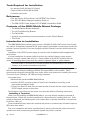
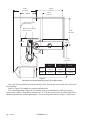
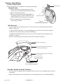
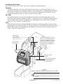
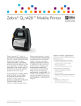
1
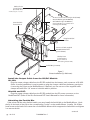
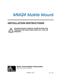
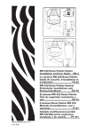
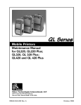
Zebra®
MM4MobileMount
VehicularMountforQln420,QL420
andP4T/RP4TMobilePrinterSeries
SafetyguideandInstallationInstructions
P1005089 Rev. C
January, 2013
Special Notices
The following notices emphasize certain information in the guide. Each serves a special
purpose and is displayed in the format shown:
Note: Note is used to emphasize any significant information.
Caution: Indicates information that, if not followed, can result in damage to software, hardware,
or data.
Caution: This symbol indicates a potentially hazardous situation which, if not avoided, can result
in personal injury.
Caution: This warning symbol indicates a potentially hazardous situation which, if not avoided,
may be a shock hazard.
Warning: This warning symbol indicates an imminently hazardous situation which, if not
avoided will result in death or serious injury. Before you work on any equipment, be aware of the
hazards involved with electrical circuitry and be familiar with standard practices for preventing
accidents.
General Warnings and Cautions
Caution: Only trained and qualified personnel should be allowed to install, replace, or service this
equipment.
Caution: Read the installation instructions before you connect the system to its power source.
Note: Zebra Technologies Corporation is not liable for personal injury or damage to any equipment
caused by the improper mechanical installation of this equipment or improper connection to any
power source. Check with the vehicle manufacturer or dealer for installation assistance in order
to prevent the voiding of the vehicle warranty or maintenance contract. Warning: Risk of ignition or explosion. Explosive gas mixture may be vented from the vehicle
battery. Work only in a well ventilated area. Avoid creating arcs and sparks at the battery
terminal
pg. 2 of 13
P1005089 Rev. C
MM4 Mobile Mount Safety and Installation Guide
Introduction
NOTE: Zebra Technologies Corporation is not liable for personal injury or damage to any equipment
caused by the improper mechanical installation of this equipment or improper connection to any
power source. Check with the vehicle manufacturer or dealer for installation assistance in order
to prevent the voiding of the vehicle warranty or maintenance contract.
The MM4 Mobile Mount system is designed to integrate a Zebra™ QLn420, QL 420 or a
P4T series mobile printer and optionally a Zebra DC/DC power supply into the electrical and
mechanical systems of a vehicle. Once installed it will provide intelligent charging capabilities
for the printer’s battery and protection from accidental damage to the printer.
The DC/DC modules are supplied separately from the MM4 installation Kit (p/n AK18926-3
for QL 420 & P4T and P1050667-035 for QLn420). They should be installed in accordance with
their installation guides and under the supervision of properly trained and qualified personnel.
The installation and safety warnings in this manual pertain only to the mechanical
installation of the MM4 mobile mount. Follow them closely to ensure safe, reliable
performance of the QLn420, QL 420 or P4T Printer in a mobile environment
It is important that the vehicle’s electrical system be functioning properly. The vehicle’s
charging circuit must work properly and vehicle-generated electrical “noise” must be
minimized and within specifications.
The vehicle charging circuit must neither undercharge nor over-charge the vehicle battery.
Defective ignition wiring, damaged insulation, or faulty vehicle electrical components can
cause electrical noise and excess electrical noise can be severe enough to defeat the electrical
filtering that is built into the printer. When this happens, computers and printers can behave
unpredictably.
NOTE: All of these systems must be connected in strict accordance with the instructions in this
document. Failure to install this equipment per these instructions will void the warranty.
P1005089 Rev. C
pg. 3 of 13
Tools Required for Installation
• An electrical drill, drill bits 1/4”(6 mm))
• Taps-1/4-20 and #6-32 (M6 and M3).
• Common hand tools.
References
• The QLn Series, QL Plus Series, and P4T/RP4T User Guides
• The RCLI-DC Mobile Charger Installation Guide, or
• The 50W. DC/DC Power Supply P4T (AT18488-1) Installation Guide
Contents of the MM4 Mobile Mount Package
• The Mobile Mount Bracket Assembly
• The Lift Truck Mounting Bracket
• The Fanfold Bin
• A plastic bag containing mounting hardware, and the Fanfold Spacer
• This Guide
Introduction to Installation
The MM4 Mobile Mount allows you to mount a QLn420, QL 420 or P4T printer into virtually
any vehicle. A separately supplied DC/DC power supply appropriate to each printer model can
provide a source of power to run and charge the printer’s battery from the vehicle’s electrical
system.
Installation of the DC/DC power supply is covered in the Installation Guide supplied with
each system.
In most installations, the power cable is wired to the vehicle’s battery power system
indirectly through a power take-off point. Some models of the DC/DC supplies offer the
option of accessing input power from the vehicle’s cigarette lighter or power adapter.
CAUTION: Under no circumstances should the equipment be attached directly to the vehicle’s
battery or an AC power source without a proper fuse.
Since each situation or equipment type may pose unique requirements, mounting hardware
selection and mechanical installation shall be the responsibility of the installer. Zebra
recommends using self-locking (ESN) nuts, bolts, and/or lock washers for installing the mount.
The mount is pre- drilled for 1/4” (M6) mounting hardware.
Your tasks are to:
• Mechanically install the MM4 Mobile Mount
• Install the DC/DC converter system (if used in this installation) according to the
appropriate Installation Guide
• Connect the Data I/O cable from the data terminal (if used) and the output cable from the
DC/DC supply system to the printer.
Decide where you will mount the printer, then proceed with the following instructions.
Installing a Terminal
When you are installing the MM4 Mobile Mount, you may also be installing a terminal at
the same time. Follow the terminal manufacturer’s instructions for installing their unit. If the
printer and terminal are linked together with a data cable it typically should be no longer than
six (6) feet (183 cm).
Some installations may require the terminal and printer to communicate via radio frequency
(RF) rather than cables.
Plan your installation with these considerations in mind, and locate the printer so that the
operator can easily load printing media and operate the printer’s controls.
pg. 4 of 13
P1005089 Rev. C
Mobile Mount Mechanical Installation
The MM4 Mobile Mount provides two basic mounting options, to allow maximum flexibility
in location. The DC/DC module is shipped separately and is mounted external to the Mobile
Mount, depending on the individual
location’s requirements.
It is important to leave a free zone
“W”
around the printer to allow loading of
paper and routine cleaning of the print
head. Refer to Figure 2. In addition, the
Mobile Mount allows for some rotation of
the printer to allow the best positioning for
the operator. Extra clearance should be
provided for this movement if it is desired
in the installation.
“H”
Vertical Mounting
(numbers in italics are in cm.)
“D”
height “H”
Width
“W”
Depth
“D”
depth w/ bin
21.32 in*.
11.63 in.
8.2 in.
11.07 in.
54.2 CM*
29.5 CM
20.83 CM
28.1 CM
“W”
Horizontal Mounting
(numbers in italics are in cm.)
“H”
height “H”
width
“W”
depth
“D”
depth w/
bin
14.30 in.*
11.63 in.
15.65 in.
18.00 in.
36.32*
29.5
39.75
45.72
*Includes minimum dimension to allow access to
controls.
IMPORTANT: Mount the Printer where
it will not interfere with the operator
during normal use, nor have the
potential to cause injury in case of
an accident.
“D”
Figure 1
Standard Mounting Configurations (AK18926-3 shown with QL 420. Also used with P4T))
P1005089 Rev. C
pg. 5 of 13
8.72 in.
22.15 cm
9.83 in.
24.97 cm
2.35 in.
5.97 cm
DIM. “A”
Allowance for media
cover opening
Minimum clearance for
Printer controls
9.83”
24.97 cm
2.50 in.
6.35 cm
DIM. “B”
11.50”
29.21 cm
QL 420
P4T
QLn420
Dim. “A”
5.82 in.
[14,78 cm)
5.92 in.
[15,04 cm)
7.00 in.
[17,78 cm]
Dim “b”
2.80 in.
[7,11 cm]
4.05 in.
[10,28 cm]
2.75 in
[6,98 cm]
Figure 2
Horizontal and Vertical Mounting Details (QL 420 illustrated)
Use a 1/4” (6 mm) drill bit to make mounting holes. Secure the mount with nuts, bolts, and
lock washers.
Refer to Figure 2 for details on mounting dimensions.
The mounting bracket (Figure 3) can also be used as a template for locating mounting
holes on the vehicle. Note that a clearance of .31” (7.8 mm) must be left on either side of the
Mounting Bracket for mounting hardware. The mounting dimensions in Figure 1 reflect this.
pg. 6 of 13
P1005089 Rev. C
11.00”
11.0
0"
(27.94
cm)
8.63”
8.63"
(21.92 cm)
2.00”
(5.082.01"
cm)
0.31"
ø.31”
x 4Dia.
(7.8 mm)
2.75”
(6.98 cm)
1.82”
typ.
1.82"
(4.62 cm)
.31”
(7.80.31"
mm)
2.75"
x4
0.31"typ.
31”
(7.8 mm
Figure 3
Mounting Bracket Hole Layout (not to scale)
Note that using a MM4 Mobile Mount assembly in the horizontal configuration requires
leaving a minimum access for printer controls from any overhanging horizontal surface.
(Refer to Figure 2).
CAUTION: Do not use the circular cutouts in the Mounting Bracket as the only mounting point
when using in the horizontal configuration.
Hardware to secure the Mobile Mont to the vehicle is not supplied in the kit. Recommended
fasteners are 1/4” (6 mm) diameter hex head or socket head bolts with flat washers, lock washers,
nuts and/or locking nuts.
P1005089 Rev. C
pg. 7 of 13
Printer Installation
Printer Preparation
Prepare the printer for installation by doing the following:
QLn420 only:
• Remove the carrying strap as shown in the
QLn Series User Guide and Quick Start Guide.
Metal Belt Clip
• Remove the plastic belt clip.
• Remove the metal belt clip (if applicable) by
unscrewing the two screws (SCR 6-32 X 1/4
PAN HD PHLLP NY) holding it to the printer.
• Remove the Docking Contacts Plug by
removing (2) screws.
Remove (2) screws
Docking Contacts Plug
Figure 4:
QLn420 Printer Preparation
QL 420 only:
• If your printer has a carrying strap, you must remove it by the following procedure
(Refer to Figure 5).
1. Unscrew the (2) #4-40 x 1” screws holding the top corners of the printer together.
2. Remove the Carrying Strap and the (2) Bushings.
3. Replace the Bushings back in the top corners of the printer and re-install the two
#4-40 x 1” screws
• Remove the Belt Clip from the back of the Printer (Refer to Figure 5).
Remove Carrying strap.
Replace bushings and screws after
removing carrying strap.
Remove Carrying Strap by unscrewing
corner screws
Remove Belt Clip by
removing (2) screws.
Figure 5:
QL 420 Printer Preparation
QLn420, QL420 and P4T Printers:
• If your printer is equipped with a shoulder strap, remove it by unclipping each end from
the printer.
• Ensure the battery pack is installed prior to mounting the printer in the Mobile Mount.
pg. 8 of 13
P1005089 Rev. C
Installing the Printer
The QLn420, QL 420 or P4T Printer can now be installed in the Mobile Mount.
QLn420:
Peel adhesive backer from the (4) Foam Washers and apply to the Mounting Plate over the
printer mounting holes as indicated in Figure 6. Secure the printer to the Mobile Mount Bracket
with (2) #6-32 x 3/8”Screws, (2) #6-32 x1/2” Screws, Lock Washers and Flat Washer. Do not
exceed an installation torque of 7 in/lb. [.79 Nm] on these screws.
QL 420:
Peel adhesive backer from the (4) Foam Washers and apply to the Mounting Plate over the
printer mounting holes as indicated in Figure 7. Secure the printer to the Mobile Mount Bracket
with (4) #8-32 x 3/8” Screws, Lock Washers and Flat Washers. Do not exceed an installation
torque of 7 in/lb. [.79 Nm ] on these screws.
P4T:
Peel adhesive backer from (2) Foam Washers and apply to the Mounting Plate over the printer
mounting holes as indicated in Figure 7. Secure the printer to the Mobile Mount Bracket with (2)
#8-32 x 3/8” Screws, Lock Washers and Flat Washers. Do not exceed an installation torque of
7 in/lb. [.79 Nm ] on these screws.
Washer, Foam
(p/n AT17342-1
•
4 p/u for QLn420*)
*4th Mounting Hole not visible
•
Data I/O Cable
from terminal
•
•
(2) #6-32 x 3/8” PAN Hd. Screw (p/n
P1055997): Lower Mounting Holes
(2) #6-32 x 1/2” PAN Hd. Screw (p/n
P1054427): Upper Mounting Holes
#8 Lock Washer (p/n 738002-06)
#8 Flat Washer (p/n TH-WA0612)
(4 p/u for QLn420)
Plug from DC/DC
module
1/4-20 x 1/2” Bolt, supplied
with Mobile Mount Kit
(p/n TH-SK2007)
Figure 6:
Printer Installation (P1050667-035 shown with QLn420)
Note: For customers who have the AK18296-3 kit and want to
re-use it for the QLn420, they can order P1050667-037. This
kit includes only the QLn420 mounting plate and associated
hardware.
P1005089 Rev. C
pg. 9 of 13
Washer, Foam
(p/n AT17342-1
4 p/u for QL 420*)
*4th Mounting Hole not visible
•
•
•
Data I/O Cable
from terminal
#8-32 x 3/8” Truss Hd. Screw (p/n TH-SD1405)
#8 Lock Washer (p/n TH-WB0708)
#8 Flat Washer (p/n TH-WA0712)
(4 p/u for QL 420; 2 p/u at lower set of mounting holes for P4T))
Plug from DC/DC
module
1/4-20 x 1/2” Bolt, supplied
with Mobile Mount Kit
(p/n TH-SK2007)
Washer, Foam
(p/n AT17342-1
2 p/u at lower set
of mounting holes for P4T)
Fanfold Bin (p/n 52520)
Figure 7:
Printer Installation (QL 420 shown)
Install the Output Cable from the DC/DC Module
QL 420:
Plug the output voltage cable from the DC/DC module into the battery pack connector of QL 420.
(Note: In some installations it may be easier to plug the charger cable into the battery pack prior
to securing the Printer to the Mobile Mount.) If desired, you can use one of the supplied cable
clamps and a #6-32 x 1/4” screw to hold the cable in position.
QLn420 and P4T:
Plug the output voltage cable from the DC/DC module into the DC power connector on the
Qln420 and P4T. (Refer to the QLn Series and P4T User’s Manuals for more information.)
Attaching the Fanfold Bin
If the printer will be using fanfold media, you must install the fanfold bin to the Mobile Mount. Hook
the lip on the back of the tray to the corresponding “hooks” on the mobile Mount. Install a 1/4- 20 Hex
head screw to the back of the center bar on the Mobile Mount which supports the fanfold bin and tighten
it to secure the bin.
continued
pg. 10 of 13
P1005089 Rev. C
Loading Media
Follow the loading procedures found in the QLn Series, QL 420 or P4T User’s Guide. Note
that if you are using Fanfold media, you should install the Fanfold Spacer (p/n BA16625-1)
between the printer’s media supports. The Spacer is included with the MM4 Mobile Mount Kit.
CAUTION: The Mobile Mount is designed for a maximum loading of 12 lbs [5.4kg] including the weight of media. Ensure no extra items are suspended from the Printer, the Mobile Mount Bracket of the Fanfold bin.
Printer Removal:
There is no need to remove the printer from the Mobile Mount during normal use and
cleaning. All access doors and controls can be reached with the printer secured in the mount.
To remove the printer for servicing or repairs:
• Unplug the power cable and the data I/O cable (if installed.)
• Remove the mounting screws and their associated hardware. You can access the
mounting screws through clearance holes in the Mobile Mount bracket.
Final Connections
If you are communicating data to the QLn420, QL 420 or P4T with a cable you must connect
a “Data I/O” cable between the terminal and the printer. If desired, you can use one of the
supplied cable clamps and a #6-32 x 1/4” screw to hold the cable in position. Consult the
factory for information on the various I/O data cables offered by Zebra for use with a variety of
widely used terminals.
NOTE: This unit was tested with shielded cables on the peripheral devices. Shielded cables must be used with
the unit to insure compliance.
DC/DC Module Installation
NOTE: Always refer to any documentation included with the DC/DC Module for complete information on installing
the DC/DC Module.
DC/DC Modules for use with MM4
Description
DC/DC p/n Input Voltage
Used On RCLI-DC Mobile Charger 12 VDC
CC16614-G1
12 VDC
QL 420
RCLI-DC Mobile Charger 9-30V
CC16614-G2
9-30 VDC
QL 420
RCLI-DC Mobile Charger 30-60V
CC16614-G3
30-60 VDC
QL 420
CC16614-G9
12 VDC
QL 420
Li-Ion DC/DC 15 - 60 VDC adapter
AK18913-003
15-60 VDC
P4T/RP4T/ QLn420
Li-Ion DC/DC 12-15 VDC ADAPTER
AK18831-2
12-15 VDC
P4T/RP4T/QLn420
RCLI-DC Mobile Charger 12 VDC
(w/ plug for cigarette lighter socket)
DC/DC Module Location
Locate the DC/DC Module in a location convenient to the printer. Follow these guidelines:
• Select a location in the vehicle that will avoid personal contact in case of an accident.
• Place the Module so that you can easily unplug the charger’s output cable from the
printer.
• Route the Module’s output cable to prevent undue strain being placed on the
connection to the printer.
• Make sure that cable routing does not invite damage to the cable.
• RCLI DC/DC module series: Secure the module with #6 (3mm) hardware using the
mounting flanges molded into the module cover. Insure that the mounting hardware
will not become loose due to vibration by using locking hardware or prevailing torque
fasteners.
P1005089 Rev. C
pg. 11 of 13
Connect the Printer
QL420: Plug the output cable from the module to the battery connection on the printer.
(Refer to the QL 420 User’s Manual for more information.) It may be easier to plug in the
charger connector before mounting the Printer to the Mobile Mount bracket.
P4T/RP4T: Plug the output cable from the module into the power connection on the printer.
(Refer to the P4T User’s Manual for more information.) It may be easier to plug in the
module output connector to the printer before mounting the Printer to the Mobile Mount
bracket.
Both Printer Series: Turn the input power source for the DC/DC module on, and verify that
the indicator lights on the DC/DC module are lit and it is functioning properly.
RCLI series only: Refer to Table 1 in the RCLI Mobile Charger Installation Guide for
indicator display information.
Connecting a Terminal
If you are also installing a terminal in the vehicle, you normally must run two separate cables
from the vehicle power source: one to the printer and one to the terminal. The terminal power
cable must be either supplied by the terminal manufacturer or fabricated by the installer.
It is the installer’s responsibility to determine the suitability of running a terminal from the
vehicle’s battery.
IMPORTANT: Zebra Technologies Corporation is not liable for personal injury or damage to
equipment caused by improper installation to any power source.
Installation Kit
The following list of parts is included with the MM4 Mobile Mount Kit. They are intended for
use in the installation of the QLn420, QL 420, P4T, and/or printer and routing power and data
I/O cables.
Part
Description
Qty
TH-SK2007
Screw, /4-20 x /2” Hex hd.
5
30466
Washer .62 O.D.
4
THRMP22CC370187
Clamp, Cable
2
TH-SD1203B
Screw #6-32 x 1/4” Blk
2
TH-SD1405
Screw, #8-32 x /8” Truss Hd.
4
P1055997
SCR 6-32 X 3/8 PAN HD PHLLP NYLOK
2
1
1
3
P1054427
SCR 6-32 X 1/2 PAN HD PHLLP NY
2
TH-WB0708
Washer, Lock # 8
4
TH-WA0712
Washer, Flat # 8
4
TH-WA0612
WSHR FLAT #6
4
738002-06
WSHR,LOCK,SPLIT,#6,SS
4
AT17342-1
WASHER, 1/4” FOAM W/ADHESIVE
4
BA16625-1
Spacer, Fan-Fold QL 420
1
52520
Bin
1
505203
Bracket Mntd Lift Truck
1
NOTES: Mounting hardware for securing the Mobile Mount to the vehicle is not supplied in the kit. Recommended
fasteners for the Mobile Mount are 1/4” (6 mm) diameter hex head or socket head bolts with flat washers, lock
washers, nuts and/or locking nuts.
Recommended fasteners for the RCLI series DC/DC modules are #6-32 (M3) bolts, flat washers and lock washers
pg. 12 of 13
P1005089 Rev. C
Printer Technical Support
When calling with a specific problem regarding the printers used in conjunction with the MM4
Mobile Mount, please have the following information on hand:
• Printer Model number/type (e.g. QL 420 or P4T)
• Printer serial number
• Printer Product Configuration Code (PCC)
• Type and model number of the DC/DC module you are using with the MM4 Mobile
Mount.
For on-line product support and the most recent versions of downloadable user documentation, firmware
and software utilities, go to the Zebra Web site: www.zebra.com
In the Americas contact
Regional Headquarters
Technical Support
Customer Service Dept.
Zebra Technologies Corporation
475 Half Day Road, Suite 500
Lincolnshire, Illinois 60069 USA
Phone: +1.847.634.6700 or
+1.866.230.9494
Fax: +1.847.913.8766
T: +1 877 275 9327
F: +1 847 913 2578
Hardware:
For printers, parts, media,
and ribbon, please call your
distributor, or contact us.
T: +1 877 275 9327
E: [email protected]
[email protected]
Software:
[email protected]
In Europe, Africa, the Middle East, and India contact
Regional Headquarters
Zebra Technologies Europe Limited
Dukes Meadow
Millboard Road
Bourne End
Buckinghamshire SL8 5XF, UK
T: +44 (0)1628 556000
F: +44 (0)1628 556001
Technical Support
T: +44 (0) 1628 556039
F: +44 (0) 1628 556003
E: [email protected]
Internal Sales Dept.
For printers, parts, media,
and ribbon, please call
yo ur dis trib uto r, o r
contact us.
T: +44 (0) 1628 556032
F: +44 (0) 1628 556001
E: [email protected]
In the Asia Pacific region contact
Regional Headquarters
Technical Support
Customer Service
Zebra Technologies Asia Pacific
Pte. Ltd.
120 Robinson Road
#06-01 Parakou Building
Singapore 068913
T: +65 6858 0722
F: +65 6885 0838
T: +65 6858 0722
F: +65 6885 0838
E: (China)
For printers, parts, media,
and ribbon, please call your
distributor, or contact us.
T: +65 6858 0722
F: +65 6885 0836
E: (China) [email protected]
All other areas:
[email protected]
All other areas:
[email protected]
[email protected]
Zebra Technologies Corporation
475 Half Day Road, Suite 500
Lincolnshire, IL 60069 USA
T: +1 847.634.6700 or +1 800.423.0442
Printed in China
on chlorine-free
recycled paper
p. 13 of 13 P1005089 rev. C
P1005089