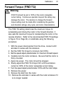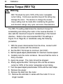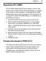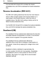
1
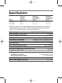
User’s Manual Models: 175720.00 175721.00 SCR, Dual Voltage, Adjustable-Speed Regenerative Drives for DC Brush Motors Copyright 2003 by Leeson Electric All rights reserved. No part of this manual may be reproduced or transmitted in any form without written permission from Leeson Electric. The information and technical data in this manual are subject to change without notice. Leeson Electric and its Divisions make no warranty of any kind with respect to this material, including, but not limited to, the implied warranties of its merchantability and fitness for a given purpose. Leeson Electric and its Divisions assume no responsibility for any errors that may appear in this manual and make no commitment to update or to keep current the information in this manual. mvd082103 Printed in the United States of America. i Safety Warnings SHOCK HAZARD AVOID HEAT KEE DR OID ATION • Throughout this manual, this symbol denotes an important safety message. Please read these messages carefully before performing any instructions contained herein. • Have a qualified electrical maintenance technician install, adjust and service this equipment. Follow the National Electrical Code and all other applicable electrical and safety codes, including the provisions of the Occupational Safety and Health Act (OSHA), when installing equipment. • Reduce the chance of an electrical fire, shock, or explosion by proper grounding, over-current protection, thermal protection and enclosure. Follow sound maintenance procedures. • It is possible for a drive to run at full speed as a result of a component failure. To stop the drive in an emergency, please ensure that a master switch has been placed in the AC line. • This drive is not isolated from earth ground. Circuit potentials are at 115 VAC or 230 VAC above earth ground. Avoid direct contact with the printed circuit board or with circuit elements to prevent the risk of serious injury or fatality. Use a non-metallic screwdriver for adjusting the calibration trimpots. ii Contents Specifications 1 Dimensions 2 Regenerative Drives 4 Installation 6 Mounting chassis drives . . . . . . . . . . . . . . . . . . . . . . . . . . . . . . . .6 Mounting cased drives . . . . . . . . . . . . . . . . . . . . . . . . . . . . . . . . . .7 Heat sinking . . . . . . . . . . . . . . . . . . . . . . . . . . . . . . . . . . . . . . . . . .8 AC line and motor connections . . . . . . . . . . . . . . . . . . . . . . . . . . .8 Cage-clamp terminal block . . . . . . . . . . . . . . . . . . . . . . . . . . . . .10 Field output . . . . . . . . . . . . . . . . . . . . . . . . . . . . . . . . . . . . . . . . .11 Tachogenerator feedback . . . . . . . . . . . . . . . . . . . . . . . . . . . . . .11 Speed adjust potentiometer installation . . . . . . . . . . . . . . . . . . . .12 Speed adjust potentiometer connections . . . . . . . . . . . . . . . . . . .13 +15 and –15 terminals . . . . . . . . . . . . . . . . . . . . . . . . . . . . . . . . .14 Line Fusing . . . . . . . . . . . . . . . . . . . . . . . . . . . . . . . . . . . . . . . . .15 Factory Prewired Connections 16 Operation 18 Before applying power . . . . . . . . . . . . . . . . . . . . . . . . . . . . . . . . .18 Check selector switch settings . . . . . . . . . . . . . . . . . . . . . . . . . .18 Startup . . . . . . . . . . . . . . . . . . . . . . . . . . . . . . . . . . . . . . . . . . . . .20 Block Diagram 22 Starting and Stopping Methods 24 Line Starting and Stopping . . . . . . . . . . . . . . . . . . . . . . . . . . . . . .24 Automatic restart upon power restoration . . . . . . . . . . . . . . . . . .24 Regenerative deceleration . . . . . . . . . . . . . . . . . . . . . . . . . . . . .24 Regenerative brake . . . . . . . . . . . . . . . . . . . . . . . . . . . . . . . . . . .25 Coast to a stop . . . . . . . . . . . . . . . . . . . . . . . . . . . . . . . . . . . . . . .26 Decelerate to minimum speed . . . . . . . . . . . . . . . . . . . . . . . . . . .27 Contents iii Calibration 29 Application Notes 37 Troubleshooting 43 Minimum Speed (MIN SPD) . . . . . . . . . . . . . . . . . . . . . . . . . . . . .30 Maximum Speed (MAX SPD) . . . . . . . . . . . . . . . . . . . . . . . . . . .30 Forward Torque (FWD TQ) . . . . . . . . . . . . . . . . . . . . . . . . . . . . .31 Reverse Torque (REV TQ) . . . . . . . . . . . . . . . . . . . . . . . . . . . . . .32 Regulation (IR COMP) . . . . . . . . . . . . . . . . . . . . . . . . . . . . . . . . .33 Forward Acceleration (FWD ACC) . . . . . . . . . . . . . . . . . . . . . . . .33 Reverse Acceleration (REV ACC) . . . . . . . . . . . . . . . . . . . . . . . .34 Deadband (DB) . . . . . . . . . . . . . . . . . . . . . . . . . . . . . . . . . . . . . .34 Tach Generator (TACH) . . . . . . . . . . . . . . . . . . . . . . . . . . . . . . . .35 Forward-Reverse Switch . . . . . . . . . . . . . . . . . . . . . . . . . . . . . . .37 Forward-Stop-Reverse Switch . . . . . . . . . . . . . . . . . . . . . . . . . . .38 Independent Adjustable Speeds . . . . . . . . . . . . . . . . . . . . . . . . .39 Independent Forward and Reverse Speeds . . . . . . . . . . . . . . . .40 Independent Forward and Reverse Speeds with FWD-STOP-REV Switch . . . . . . . . . . . . . . . . . . . . . . . . . . .41 Voltage follower . . . . . . . . . . . . . . . . . . . . . . . . . . . . . . . . . . . . . .42 Check the following steps before proceeding . . . . . . . . . . . . . . .43 Line fuse blows . . . . . . . . . . . . . . . . . . . . . . . . . . . . . . . . . . . . . .44 Line fuse does not blow, but the motor does not run . . . . . . . . .45 Motor pulsates or surges under load . . . . . . . . . . . . . . . . . . . . . .46 Motor runs too fast at the maximum speed setting . . . . . . . . . . .46 Motor will not reach the desired speed . . . . . . . . . . . . . . . . . . . .46 Limited Warranty inside back cover iv Illustrations Figure Figure Figure Figure Figure Figure Figure Figure Figure Figure Figure Figure Figure Figure Figure Figure Figure Figure Figure Figure Figure Figure Figure Figure Figure 1. 2. 3. 4. 5. 6. 7. 8. 175721.00 (Chassis) Dimensions . . . . . . . . . . . . . . . . . . .2 175720.00 (Cased Drive) Dimensions . . . . . . . . . . . . . . .3 Four Quadrant Operation . . . . . . . . . . . . . . . . . . . . . . . . .5 Chassis Drive Connections . . . . . . . . . . . . . . . . . . . . . . . .8 Cased Drive Connections . . . . . . . . . . . . . . . . . . . . . . . . .9 Cage-Clamp Terminal Block . . . . . . . . . . . . . . . . . . . . . .10 Speed Adjust Potentiometer . . . . . . . . . . . . . . . . . . . . . .12 Speed Adjust Potentiometer Connections for Unidirectional Operation (a) and Bidirectional Operation (b) . . . . . . . . .13 9. TB502 Terminal Assignments . . . . . . . . . . . . . . . . . . . . .14 10. Prewired Connections to L1, L2 (with 115 VAC input) and L2 (with 230 VAC input) . . . . . . . . . . . . . . . . . . . . . . . .16 11. Prewired Speed Adjust Potentiometer Connections . . .17 12. Selector Switch Locations . . . . . . . . . . . . . . . . . . . . . . .19 13. Block Diagram . . . . . . . . . . . . . . . . . . . . . . . . . . . . . . . .22 14. Regenerative Deceleration Switch Connection . . . . . .24 15. Inhibit Terminals . . . . . . . . . . . . . . . . . . . . . . . . . . . . . .25 16. Inhibit-Run Terminals . . . . . . . . . . . . . . . . . . . . . . . . . .26 17. Run / Decelerate to Minimum Speed Switch (shown with bidirectional connection) . . . . . . . . . . . . . .27 18. Calibration Trimpot Layout . . . . . . . . . . . . . . . . . . . . . .29 19. Typical FWD TQ, REV TQ, IR COMP and Deadband Settings . . . . . . . . . . . . . . . . . . . . . . . . . . . . . . . . . . . . .36 20. Forward-Reverse Switch . . . . . . . . . . . . . . . . . . . . . . . .37 21. Forward-Stop-Reverse Switch . . . . . . . . . . . . . . . . . . .38 22. Independent Adjustable Speeds (Forward Direction) . . . . . . . . . . . . . . . . . . . . . . . . . . . .39 23. Independent Forward and Reverse Speeds . . . . . . . . .40 24. Independent Forward and Reverse Speeds with a Forward-Stop-Reverse Switch . . . . . . . . . . . . . . . . . . .41 25. Voltage Follower Connection . . . . . . . . . . . . . . . . . . . .42 1 Specifications Model Max. Armature Current (Amps DC) HP Range with 115 VAC Applied HP Range with 230 VAC Applied 175720.00 10.0 † 1/4 – 1 † 1/2 – 2 † 175721.00 10.0 † 1/4 – 1 † 1/2 – 2 † † Maximum armature current and horsepower range apply when drive is attached to additional heat sink part number 175722. Use heat sink when armature current is above 7 ADC. Heat sinks are pre-mounted on cased drives. AC Line Voltage 115/230 VAC, ±10%, 50/60 Hz, single phase Armature Voltage (115 VAC Input) 0 – 90 VDC Armature Voltage (230 VAC Input) 0 – 180 VDC Form Factor 1.37 at base speed Field Voltage (115 VAC Input) 50 VDC (F1 to L1); 100 VDC (F1 to F2) Field Voltage (230 VAC Input) 100 VDC (F1 to L1); 200 VDC (F1 to F2) Max. Field Current 1 ADC Accel. Time Range (with no load) 0.5 –10 seconds Decel. Time Range (with no load) 0.5 –10 seconds Analog Input Voltage Range (isolated; RB1 to S2) Input Impedance (S0 to S2) 0 –10 VDC 32K ohms Load Regulation with Armature Feedback with Tachogenerator Feedback 1% of base speed or better 0.1% of base speed Ambient Temp. Range (chassis drive) 10°C – 55°C Ambient Temp. Range (cased drive) 10°C – 40°C 2 Dimensions 8.90 [226] 8.38 [213] 3.53 [90] 4.75 [120] 1.86 [47] 0.92 [23] ALL DIMENSIONS IN INCHES [MILLIMETERS] Figure 1. 175721.00 (Chassis) Dimensions Dimensions 6.90 [175] 6.30 [160] SPEED POWER BRAKE 10.20 [259] REVERSE FORWARD 9.80 [249] FOUR (4) EACH MOUNTING SLOTS, 6.3 [160] x 7.0 [178] ON CENTERS 5.50 [140] 4.78 [121] 1.45 [37] 2.30 [58] 0.12 [3] 1.50 [38] 1.50 [38] THREE 0.88 [22] KNOCKOUTS ALL DIMENSIONS IN INCHES [MILLIMETERS] Figure 2. 175720.00 (Cased Drive) Dimensions 3 4 Regenerative Drives Most non-regenerative, variable speed, DC drives control current flow to a motor in one direction. The direction of current flow is the same direction as the motor rotation. Non-regenerative drives operate in Quadrant 1, and also in Quadrant 3 if the drive is reversible (see Figure 3). Motors must stop before reversing direction. Unless dynamic braking is used, non-regenerative drives cannot oppose an overhauling load, and cannot decelerate a load faster than coasting to a lower speed. Regenerative drives operate in two additional quadrants: Quadrant 2 and Quadrant 4. In these quadrants, motor torque is in the opposite direction of motor rotation. Regenerative drives can reverse a motor without contactors, switches, brake resistors, and inhibit plugs. They can also control an overhauling load and decelerate a load faster than it would take to coast to a lower speed. Regenerative Drives Quadrant II Quadrant I Quadrant III Quadrant IV MOTOR ROTATION MOTOR TORQUE NOTE: ARROWS IN SAME DIRECTION = MOTOR ACTION ARROWS IN OPPOSITE DIRECTION = REGENERATIVE ACTION Figure 3. Four Quadrant Operation 5 6 Installation Mounting chassis drives Warning Do not install, rewire, or remove this control with power applied. Doing so may cause fire or serious injury. Read and understand the Safety Warnings on pg i before attempting installation. Drive components are sensitive to electrostatic fields. Avoid direct contact with the circuit board. Hold the drive by the chassis only. Protect the drive from dirt, moisture, and accidental contact. Provide sufficient room for access to the terminal block and calibration trimpots. Mount the drive away from heat sources. Operate the drive within the specified ambient operating temperature range. Prevent loose connections by avoiding excessive vibration of the drive. Mount the drive with its board in either a horizontal or vertical plane. Six 0.188 inch (4.8 mm) wide slots in the chassis accept #8 pan head screws. Fasten either the large base or the narrow flange of the chassis to the subplate. The chassis must be earth grounded for noise suppression. To ground the chassis, connect earth ground to the GND terminal on terminal block TB501. Installation 7 Mounting cased drives Leeson cased drives come with three 0.88-inch (22 mm) conduit knockout holes on the bottom of the case. The units may be vertically wall mounted using the four 0.25-inch (6 mm) slotted holes on the attached heat sink. For motor loads less than 5 ADC, the drive may be bench mounted horizontally, or operated without mounting. 1. Install the mounting screws. 2. For access to the terminal strip, turn the slotted screw on the front cover counterclockwise until it is free from the case. The right side of the cover is hinged to the case. Lift or pull the slotted screw to open the case. 3. Carefully remove the conduit knockouts by tapping them into the case and twisting them off with pliers. 4. Install conduit hardware through the 0.88 inch (22 mm) conduit holes. Connect external wiring to the terminal block. 5. Grasp the slotted screw and tilt the front cover back into place. Avoid pinching any wires between the front cover and the case. 6. Turn the slotted screw clockwise until tight to secure the front cover. 7. Set the POWER switch to the “O” or OFF position before applying the AC line voltage. 8 Installation Heat sinking Model 175721.00 requires an additional heat sink, p/n 175722, when the continuous armature current is above 7 ADC. Model 175720.00 has sufficient heat sinking in its basic configuration. Use a thermally conductive heat sink compound (such as Dow Corning® 340 Heat Sink compound) between the drive chassis and the heat sink surface for optimum heat transfer. AC line and motor connections Use 12 AWG or 14 AWG standard wire for connecting the line and the armature. Use 16 AWG or 18 AWG standard wire when connecting the field of a shunt-wound motor. Strip the wire insulation 0.25 inches (6 mm). See Figures 4 and 5 for AC line (115 VAC or 230 VAC) and motor connections to chassis and cased drives. C503 IC502 S3 S2 SW501 TB501 C504 TB502 C505 L1 L2 230V L2 115V GND F1 F2 A2 230 VAC AC INPUT VOLTAGE A1 MOTOR 115 VAC FIELD OUTPUT For shunt wound motors only. See field output section for details. Figure 4. Chassis Drive Connections 9 SO501 T1 T2 INH-RUN SO502 INHIBIT Installation FU502 FU503 S0 FLD S1 115 C503 IC502 S2 SW501 S3 L2 230 FAST ACTING FUSES ONLY L1 IC501 RB1 RB2 -15 3 230 FU501 2 +15 C502 1 TB501 TB502 C504 230 VAC C505 L1 L2 230V L2 115V GND F1 F2 A2 A1 115 VAC MOTOR AC LINE INPUT FIELD OUTPUT For shunt wound motors only. See field output section for details. Figure 5. Cased Drive Connections 10 Installation Cage-clamp terminal block Connections to drives are made to a cage-clamp terminal block (Figure 6). To insert a wire into the terminal block, press down on the lever arm using a small screwdriver. Insert stripped wire into the large opening in front of the terminal block. Release the lever arm to clamp the wire. Press down on the lever arm using a small screwdriver. 1 2 Insert wire into the wire clamp. 3 Release the lever arm to clamp the wire. Figure 6. Cage-Clamp Terminal Block Installation 11 Field output The field output is for shunt wound motors only. Do not make any connections to F1 and F2 when using a permanent magnet motor. Use 18 AWG wire to connect the field output to a shunt wound motor. Table 1 lists the field output connections. Table 1. Field Output Connections Line Voltage (VAC) 115 115 230 230 Approximate Field Voltage (VDC) 50 100 100 200 Connect Motor Field To F1 and L1 F1 and F2 F1 and L1 F1 and F2 Tachogenerator feedback Using tachogenerator feedback improves speed regulation from approximately 1% of motor base speed to approximately 0.1% of motor base speed. Use tachogenerators rated from 7 VDC per 1000 RPM to 50 VDC per 1000 RPM. Connect the tachogenerator to terminals T1 and T2 of terminal block TB502. The polarity is positive (+) for T1 and negative (–) for T2 when the motor is running in the forward direction. The polarity is reversed when the motor is running in the reverse direction. 12 Installation Speed adjust potentiometer installation On chassis drives, install the circular insulating disk between the panel and the 10KΩ speed adjust potentiometer. Mount the speed adjust potentiometer through a 0.38 in. (0.96 cm) hole with the hardware provided (see Figure 7). Twist the speed adjust potentiometer wire to avoid picking up unwanted electrical noise. If the potentiometer leads are longer than 18 in. (46 cm), use shielded cable. Speed adjust potentiometers are installed on all cased drives. Warning Be sure that the potentiometer tabs do not make contact with the potentiometer enclosure. Grounding the input will cause damage to the drive. MOUNT THROUGH A 0.38 IN. (10 MM) HOLE CW WIPER W NUT STAR WASHER SPEED ADJUST POTENTIOMETER INSULATING DISK PANEL Figure 7. Speed Adjust Potentiometer 13 Installation Speed adjust potentiometer connections The motor can operate in one direction (unidirectional) or in two directions (bidirectional) depending on how the speed adjust potentiometer is connected to the drive. Connect the speed adjust potentiometer as shown in Figure 8(a) for speed control in one direction. Connect the speed adjust potentiometer as shown in Figure 8(b) for speed control in two directions. The motor does not rotate when the wiper is in the center position. Turning the wiper CW from the center position causes the motor to rotate in one direction, while turning the wiper CCW from the center position causes the motor to rotate in the opposite direction. Refer to the Application Notes section (page 37) for additional speed adjust potentiometer connections. S0 CW FWD CW S1 S1 10K (a) S2 S3 TB502 S3 TB502 S2 REV 10K (b) Figure 8. Speed Adjust Potentiometer Connections for Unidirectional Operation (a) and Bidirectional Operation (b) 14 Installation TB502 S3 S2 S1 S0 RB1 RB2 -15 +15 T1 T2 Figure 9. TB502 Terminal Assignments +15 and –15 terminals 17572x Series drives can supply a regulated +15 and –15 VDC signal (each sourcing 25 mA maximum) to isolated, external devices. These voltage supply terminals are located on terminal block TB502. Warning Do not short the +15 and - 15 terminals for any reason! Shorting these terminals will damage the drive. Installation 15 Line Fusing Leeson drives require fuses for protection. Use fast acting fuses rated for 250 VAC or higher, and approximately 150% of the maximum armature current. Fuse both L1 and L2 when the line voltage is 230 VAC. The fuse table below lists the recommended line fuse sizes. Fuse Table 90 VDC Motor Horsepower 1/20 1/15 1/8 1/6 1/4 1/3 1/2 3/4 1 180 VDC Max. DC Armature AC Line Fuse Horsepower Current (amps) Size (amps) 1/10 0.5 3 1/8 0.8 3 1/4 1.5 5 1/3 1.7 5 1/2 2.5 8 3/4 3.5 8 1 5.0 10 1 1/2 7.5 15 2 10 20 16 Factory Prewired Connections (for Cased Drives) 1 2 3 WHITE/BLACK WHITE/BLACK L2 (230) BLACK BLACK POWER LIGHT BLACK L1 BLACK/WHITE WHITE/BLACK L2 (115) Figure 10. Prewired Connections to L1, L2 (with 115 VAC input) and L2 (with 230 VAC input) Factory Prewired Connections S0 GREY FWD BRAKE S1 BLUE/ WHITE GREY/WHITE REV CW BROWN TB502 S2 PURPLE S3 10K Figure 11. Prewired Speed Adjust Potentiometer Connections 17 18 Operation Before applying power 1. Check connections before applying AC line voltage to the drive. 2. Check that no conductive material is present on the printed circuit board. 3. Verify that all selector switches are set correctly (see the following section for selector switch settings). Check selector switch settings 1. Set both line voltage selector switches (SW501 and SW502) to 115 if using 115 VAC line voltage, or to 230 if using 230 VAC line voltage. 2. Set the armature voltage selector switch (SW503) to 90 if using a 90 VDC motor, or to 180 if using a 180 VDC motor. 3. Set the feedback selector switch (SW504) to TACH if using a tachogenerator; otherwise, set it to ARM for armature feedback. Note: You may be required to derate a 90 VDC motor when 230 VAC is applied to the drive. Contact Leeson for details. See Figure 12 on page 19 for switch locations. Operation VOLTAGE SELECT SWITCHES ARMATURE SELECT SWITCH FEEDBACK SELECT SWITCH Figure 12. Selector Switch Locations 19 20 Operation Startup Chassis drives Uni-directional Operation 1. Set the speed adjust potentiometer to minimum (full CCW). 2. Apply AC line voltage. 3. Slowly turn the speed adjust potentiometer clockwise (CW). The motor will accelerate as the potentiometer is turned CW. Continue until the desired speed is reached. 4. Remove AC line voltage from the drive to coast the motor to a stop. Bi-directional Operation 1. Set the speed adjust potentionmeter to minimum (center position). 2. Apply AC line voltage. 3. Slowly turn the speed adjust potentiometer either clockwise for forward direction, or counterclockwise for reverse direction. The motor will accelerate as the potentiometer is turned. Continue until the desired speed is reached. 4. Remove AC line voltage from the drive to coast the motor to a stop. Operation 21 Cased drives 1. 2. 3. 4. 5. Set the FORWARD / BRAKE / REVERSE switch to BRAKE. Set the speed adjust potentiometer to minimum (full CCW). Apply AC line voltage. Set the POWER switch to the “ I ” (ON) position. Set the FORWARD / BRAKE / REVERSE switch to the desired direction of rotation. 7. Slowly advance the speed adjust potentiometer clockwise (CW). The motor will accelerate as the potentiometer is turned CW. Continue until the desired speed is reached. 8. To brake the motor, set the FORWARD / BRAKE / REVERSE switch to the BRAKE position. To coast the motor to a stop, set the POWER switch to the “ 0 ” (OFF) position. 9. To reverse direction: a. Set the FORWARD / BRAKE / REVERSE switch to BRAKE. b. After the motor comes to a complete stop, set the FORWARD / BRAKE / REVERSE switch to the desired direction of rotation. 10. Set the POWER switch to “ 0 ” (OFF) to remove power from the drive. 22 Block Diagram Figure 13. Block Diagram Block Diagram 23 24 Starting and Stopping Methods Line Starting and Stopping Line starting and stopping (applying and removing AC line voltage) is recommended only for infrequent starting and stopping of a drive. When AC power is applied to the drive, the motor accelerates to the speed set by the speed adjust potentiometer. When power is removed, the motor coasts to a stop. Automatic restart upon power restoration All drives automatically run to set speed when power is applied. Wiring a latching relay into the AC line is one way to prevent automatic restarting following a power outage. Regenerative deceleration Short terminals RB1 and RB2 to regeneratively decelerate a motor to a stop (Figure 14). Since terminal RB1 bypasses the MIN SPD circuit, shorting RB1 and RB2 will decelerate a motor to a stop instead of minimum speed. Calibrate the deceleration time by adjusting the opposite-direction acceleration trimpot. RB1 STOP RB2 RUN Figure 14. Regenerative Deceleration Switch Connection Starting and Stopping Methods 25 Regenerative brake Short the INHIBIT terminals to regeneratively brake the motor (see Figure 15 for INHIBIT terminal location). Reopening the INHIBIT terminals causes the motor to run at set speed. The INHIBIT terminals bypass both the MIN SPD circuit and the deceleration circuit. This causes the motor to stop rapidly when the INHIBIT terminals are shorted. Braking torque is determined by the opposite-direction torque setting. INHIBIT TERMINALS Figure 15. Inhibit Terminals 26 Starting and Stopping Methods Twist inhibit wires and separate them from other power-carrying wires or sources of electrical noise. Use shielded cable if the inhibit wires are longer than 18 in. (46 cm). If shielded cable is used, ground only one end of the shield to earth ground. Do not ground both ends of the shield. Coast to a stop To coast the motor to a stop without removing power to the drive, jumper INHIBIT–RUN terminals 1 and 2 (see Figure 16). To restart the motor, jumper INHIBIT–RUN terminals 2 and 3. A single-pole, double-throw switch may be used as a COAST / RUN switch. Each drive is assembled with INHIBIT-RUN terminals 2 and 3 jumpered. These terminals must be connected for the motor to run. INHIBIT/RUN TERMINALS Figure 16. Inhibit-Run Terminals Starting and Stopping Methods 27 Decelerate to minimum speed The circuit shown in Figure 17 may be used to decelerate a motor to a minimum speed. Closing the switch between S2 and S0 decelerates the motor from set speed to a minimum speed determined by the MIN SPD trimpot setting. If the MIN SPD trimpot is set full CCW, the motor decelerates to zero speed when the switch between S2 and S0 is closed. The DECEL trimpot setting determines the rate at which the drive decelerates. Set the switch to the RUN position to accelerate the motor to set speed at a rate determined by the ACCEL trimpot setting. REV 10K S3 RUN S2 DECEL TO MIN SPD S1 CW S0 TB502 FWD Figure 17. Run / Decelerate to Minimum Speed Switch (shown with bidirectional connection) 28 Starting and Stopping Methods Warning For frequent starts and stops, use regenerative deceleration (shorting RB1 and RB2), regenerative breaking (shorting INHIBIT terminals to each other), coasting to a stop (shorting INHIBIT-RUN terminals 1 and 2), or decelerating to minimum speed (shorting S2 to S0). Do not use any of these methods for emergency stopping. They may not stop a drive that is malfunctioning. Removing AC line power (both L1 and L2) is the only acceptable method for emergency stopping. Certain Leeson drives (regenerative and non-regenerative) coast to minimum speed when the inhibit terminals are shorted to each other. IR COMP and CURRENT LIMIT (FWD TQ and REV TQ on regnerative drives) are still active while the drive is in the inhibit mode. Frequent regenerative deceleration, regenerative braking, coasting to a stop, or decelerating to minimum speed produces high torque. This may cause damage to motors, especially gearmotors that are not properly sized for the application. 29 Calibration Each drive is factory calibrated to its maximum current rating. Readjust the calibration trimpot settings to accommodate lower current rated motors. All adjustments increase with CW rotation, and decrease with CCW rotation. Use a non-metallic screwdriver for calibration. Each trimpot is identified on the printed circuit board. P501 P502 P503 MIN SPD FWD TQ REV TQ P504 P505 P506 IR COMP MAX SPD FWD ACC P507 P508 P509 REV ACC DB TACH Figure 18. Calibration Trimpot Layout 30 Calibration Minimum Speed (MIN SPD) The MIN SPD setting determines the minimum speed when the speed adjust potentiometer is turned full CCW. It is factory set to zero speed. The minimum speed feature applies only when the drive is operating in unidirectional mode. To calibrate, set the speed adjust potentiometer full CCW. Adjust the MIN SPD trimpot until the motor turns at the desired minimum speed. Maximum Speed (MAX SPD) The MAX SPD setting determines the maximum motor speed when the speed adjust potentiometer is turned full CW. It is factory set for maximum rated motor voltage. To calibrate, set the speed adjust potentiometer full CW. Adjust the MAX SPD trimpot until the motor turns at the desired maximum speed. Calibration 31 Forward Torque (FWD TQ) Warning FWD TQ should be set to 120% of the motor nameplate current rating. Continuous operation beyond this rating may damage the motor. The decision to change the forward torque setting must be made after considering the gearbox and drivetrain ratings, duty cycle, and motor characteristics. The FWD TQ setting determines the maximum torque for accelerating and driving the motor in the forward direction. It also sets the maximum torque for decelerating the motor in the reverse direction. Refer to the recommended FWD TQ settings in Figure 19 on Page 36, or recalibrate using the following procedure: 1. With the power disconnected from the drive, connect a DC ammeter in series with the armature. 2. Set the FWD TQ trimpot to minimum (full CCW). 3. Set the speed adjust potentiometer for maximum forward speed. 4. Carefully lock the motor armature. Be sure that the motor is firmly mounted. 5. Apply line power. The motor should be stopped. 6. Slowly adjust the FWD TQ trimpot CW until the armature current is 120% of the motor nameplate current rating. 7. Turn the speed adjust potentiometer CCW until the motor stops. 8. Remove line power. 9. Remove the stall from the motor. 10. Remove the ammeter in series with the motor armature if it is no longer needed. 32 Calibration Reverse Torque (REV TQ) Warning REV TQ should be set to 120% of the motor nameplate current rating. Continuous operation beyond this rating may damage the motor. The decision to change the reverse torque setting must be made after considering the gearbox and drivetrain ratings, duty cycle, and motor characteristics. The REV TQ setting determines the maximum torque for accelerating and driving the motor in the reverse direction. It also sets the maximum torque for decelerating in the forward direction. Refer to the recommended REV TQ settings in Figure 19 on Page 36, or recalibrate using the following procedure: 1. With the power disconnected from the drive, connect a DC ammeter in series with the armature. 2. Set the REV TQ trimpot to minimum (full CCW). 3. Set the speed adjust potentiometer for maximum reverse speed. 4. Carefully lock the motor armature. Be sure that the motor is firmly mounted. 5. Apply line power. The motor should be stopped. 6. Slowly adjust the REV TQ trimpot CW until the armature current is 120% of the motor nameplate current rating. 7. Turn the speed adjust potentiometer CCW until the motor stops. 8. Remove line power. 9. Remove the stall from the motor. 10. Remove the ammeter in series with the motor if it is no longer needed. Calibration 33 Regulation (IR COMP) The IR COMP setting determines the degree to which motor speed is held constant as the motor load changes. It is factory set for optimum motor regulation. Recalibrate the IR COMP setting when using a lower horsepower motor. See Figure 19 on page 36 for typical IR COMP settings, or recalibrate using the following procedure: 1. Set the IR COMP trimmer pot to minimum (full CCW). 2. Set the speed adjust potentiometer to run at mid-speed without load (for example, 900RPM for an 1800 RPM motor). A hand held tachometer may be used to measure motor speed. 3. Load the motor to the nameplate current rating (full load). The motor should slow down. 4. While keeping the load on the motor, adjust the IR COMP trimmer pot CW until the motor runs at the speed measured in step 2. 5. Unload the motor. Forward Acceleration (FWD ACC) The FWD ACC setting determines the time the motor takes to ramp to either a higher speed in the forward direction or a lower speed in the reverse direction, within the limits of available torque. The FWD ACC setting is factory set for its fastest forward acceleration time. 34 Calibration Turn the FWD ACC trimpot CW to increase the forward acceleration time, and CCW to decrease the forward acceleration time. Reverse Acceleration (REV ACC) The REV ACC setting determines the time the motor takes to ramp to either a higher speed in the reverse direction or a lower speed in the forward direction, within the limits of available torque. The REV ACC setting is factory set for its fastest reverse acceleration time. Turn the REV ACC trimpot CW to increase the reverse acceleration time, and CCW to decrease the reverse acceleration time. Deadband (DB) The deadband trimmer potentiometer determines the time that will elapse between the application of current in one direction before current is applied in the opposite direction. The deadband trimmer potentiometer affects the resistance that a motor has to changes in shaft position at zero speed. It does this by applying AC voltage to the motor armature. Deadband is factory calibrated to approximately the 3 o’clock position for 60 Hz AC line operation. Recalibrate the deadband to the 9 o’clock position for 50 Hz AC line operation. See Figure 19 on page 36 for recommended deadband settings. Calibration 35 Tach Generator (TACH) Calibrate the TACH setting only when a tachogenerator is used. The TACH setting, like the IR COMP setting, determines the degree to which motor speed is held constant as the motor load changes. To calibrate the TACH trimpot: 1. Connect the tachogenerator to T1 and T2. The polarity is positive (+) for T1 and negative (–) for T2 with the motor running in the forward direction. 2. Set switch SW504 to ARM for armature feedback. 3. Set the speed adjust potentiometer full CW. Measure the armature voltage across A1 and A2 using a voltmeter. 4. Set the speed adjust potentiometer to 0 (zero speed). 5. Set switch SW504 to TACH for tachogenerator feedback. 6. Set the IR COMP trimpot full CCW. 7. Set the TACH trimpot full CW. 8. Set the speed adjust potentiometer full CW. 9. Adjust the TACH trimpot until the armature voltage is the same value as the voltage measured in step 3. Check that the tachogenerator is properly calibrated. The motor should run at the same set speed when SW504 is set to either armature or tachogenerator feedback. 36 FWD TQ FWD TQ FWD TQ FWD TQ Calibration REV TQ REV TQ REV TQ REV TQ IR COMP IR COMP IR COMP IR COMP 1 HP 90 VDC 10 ADC FWD TQ 3/4 HP 90 VDC 7.6 ADC FWD TQ 1/2 HP 90 VDC 5 ADC FWD TQ 1/4 HP 90 VDC 2.7 ADC FWD TQ 60 Hz Applications 50 Hz Applications DB DB REV TQ REV TQ REV TQ REV TQ IR COMP IR COMP IR COMP IR COMP 2 HP 180 VDC 9.2 ADC 1 HP 180 VDC 5 ADC 3/4 HP 180 VDC 3.8 ADC 1/2 HP 180 VDC 2.5 ADC Figure 19. Typical FWD TQ, REV TQ, IR COMP and Deadband Settings 37 Application Notes Forward-Reverse Switch Use a single-pole, two-position switch with a single speed adjust potentiometer to plug reverse the motor (Figure 20). The MIN SPD setting is in effect for either direction. S0 S1 10K OHM TB502 S2 REV CW S3 FWD Figure 20. Forward-Reverse Switch 38 Application Notes Forward-Stop-Reverse Switch Use a single-pole, three-position switch with a single speed adjust potentiometer to stop a motor between reversals (Figure 21). Set the switch to the center position to decelerate the motor to a stop. S0 S1 10K OHM TB502 S2 S3 REV CW STOP FWD Figure 21. Forward-Stop-Reverse Switch Application Notes 39 Independent Adjustable Speeds Connect two speed adjust potentiometers with a single pole two position switch to select between two independent speeds shown in the forward direction (Figure 22). The speed adjust potentiometers can be mounted at two separate operating stations. P1 20K OHM S0 TB502 S1 SPEED 1 CW S2 SPEED 2 Figure 22. Independent Adjustable Speeds (Forward Direction) P2 20K OHM CW 40 Application Notes Independent Forward and Reverse Speeds Connect two speed adjust potentiometers as shown in Figure 23 to select between independent forward and reverse. S0 FWD 10K OHM REV 10K OHM S1 TB502 FWD CW CW S2 S3 REV Figure 23. Independent Forward and Reverse Speeds Application Notes 41 Independent Forward and Reverse Speeds with FWD-STOP-REV Switch Use a single pole, three position switch to stop the motor when the switch is in the center position (Figure 24). S0 S1 TB502 S2 S3 FWD 10K OHM FWD CW REV 10K OHM CW STOP REV Figure 24. Independent Forward and Reverse Speeds with a Forward-Stop-Reverse Switch 42 Application Notes Voltage follower The drive may be wired to follow a floating (isolated) 0 to ±10V signal that is isolated from earth ground instead of using a speed adjust potentiometer. Connect the signal input to S2, and the signal common to RB1 (see Figure 25). ±10 VDC S2 S1 RB1 TB502 COMMON Figure 25. Voltage Follower Connection 43 Troubleshooting Warning Dangerous voltages exist on the drive when it is powered. When possible, disconnect the drive while troubleshooting. High voltages can cause serious or fatal injury. Check the following steps before proceeding 1. The AC line voltage must match the voltage on the drive nameplate. 2. On dual voltage drives, check that the voltage switches are set to the correct position. 3. The deadband (DB) must be set approximately at the 3 o’clock position for 60 Hz AC line frequency or at 9 o’clock for 50 Hz AC line frequency. 4. The motor must be rated for the drive’s rated armature (all motors) and field outputs (shunt wound motors only). 5. Do not make any connections to F1 and F2 if using a permanent magnet motor. 6. Terminal block connections should be consistent with the connections shown in this manual. 7. Check that line fuse FU501 (and FU502 for 230 VAC input) is properly sized and not blown. 44 Troubleshooting Line fuse blows 1. Disconnect AC line voltage from the drive. 2. Check that the motor cable and armature are not shorted or grounded. a. Armature resistance should measure approximately 1 to 100 ohms, depending on motor horsepower. b. A resistance reading from the motor frame to either armature side should show open when an ohmmeter is used on its high resistance scale. 3. Check that the field circuit is not open. 4. A combination of ambient conditions and frequent high-current spikes (i.e., reversing) causes fuse to “nuisance trip”. Consider using a slow-blow fuse or increasing the fuse rating to 120% of motor current as stated on the nameplate. Troubleshooting 45 Line fuse does not blow, but the motor does not run 1. Verify that the speed adjust potentiometer is not set to its zero speed position. 2. Check the speed adjust potentiometer for continuity. 3. Verify that the inhibit terminals are not shorted together. 4. Check that INHIBIT–RUN terminals 2 and 3 are connected. (See figure 16, page 25) 5. Verify that the drive is receiving AC line voltage. 6. Check that the drive is not in current limit. If the drive is in current limit, verify that the motor is not jammed. It may be necessary to increase the FWD TQ or REV TQ setting if it is set lower than the current rating of the motor. 7. Check that the speed adjust potentiometer connections to the terminal block are correct and not open. 46 Troubleshooting Motor pulsates or surges under load 1. IR Comp may be set too high. Adjust the IR COMP setting slightly CCW until the motor speed stabilizes. 2. Motor “bouncing” in and out of torque limit. Make sure the motor is not undersized for the load; adjust FWD TQ and REV TQ trimpots. Motor runs too fast at the maximum speed setting 1. Check that the MIN SPD and MAX SPD settings are not set too high. 2. If using a shunt-wound motor, check that the field output connections are secure. Motor will not reach the desired speed 1. Check the MAX SPD setting and increase if necessary. 2. Check that the IR COMP setting is not set too low. 3. Check that the motor is not overloaded. For additional assistance, contact your local Leeson distributor, or the factory direct: phone (262) 3778810; fax (262) 377-9025. 47 NOTES 48 NOTES Limited Warranty A. Warranty - Leeson Electric warrants that this product will be free from defects in workmanship and material for one (1) year or 3,000 hours, whichever comes first, from date of shipment therof. Within this warranty period, Leeson Electric will repair or replace such products that are : (1) returned to Leeson Electric, 2100 Washington Street, Grafton, WI, 53024-0241 U.S.A ; and, (2) determined by Leeson Electric to be defective. This warranty shall not apply to any product that has been subject to misuse, negligence, or accident; or misapplied; or repaired by unauthorized persons; or improperly installed. Leeson Electric is not responsible for removal, installation, or any other incidental expenses incurred in shipping the product to and from the repair point. B. Disclaimer - The provisions of Paragraph A are Leeson Electric’s sole obligation and exclude all other warranties of merchantability for use, express or implied. Leeson Electric further disclaims any responsibility whatsoever to the customer or to any other person for injury to the person or damage or loss of property of value caused by any product that has been subject to misuse, negligence, or accident, or misapplied or modified by unauthorized persons or improperly installed. C. Limitations of Liability - In the event of any claim for breech of any of Leeson Electric’s obligations, whether express or implied, and particularly of any other claim or breech of warranty contained in Paragraph A, or of any other warranties, express or implied, or claim of liability that might, despite Paragraph B, be decided against Leeson Electric by lawful authority, Leeson Electric shall under no circumstances be liable for any consequential damages, losses, or expense arising in connection with the use of, or inability to use, Leeson Electric’s product for any purpose whatsoever. An adjustment made under warranty does not void the warranty, nor does it imply an extension of the original one (1) year or 3,000 hour warranty period. Products serviced and/or parts replaced on a no-charge basis during the warranty period carry the unexpired portion of the original warranty only. If for any reason any of the foregoing provisions shall be ineffective, Leeson Electric’s liability for damages arising out of its manufacture or sale of equipment, or use thereof, whether such liability is based on warranty, contract, negligence, strict liability in tort, or otherwise, shall not in any event exceed the full purchase price of such equipment. Any action against Leeson Electric based upon any liability or obligation arising hereunder or under any law applicable to the sale of equipment or the use thereof, must be commenced within one year after the cause of such action arises. 2100 Washington Street Grafton, WI 53024-0241 U.S.A. Phone: (262) 377-8810 Fax: (262) 337-9025 Document number 250–0254, Revision 4 Printed in the U.S.A – May 2007