1
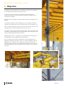
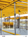
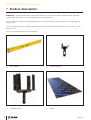
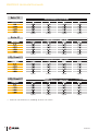
ENKOFLEX Horizontal Formwork
Construcción
IMPORTANT:
Any safety provisions as directed by the appropriate governing
agencies must be observed when using our products.
The pictures in this brochure are snapshots of situations at different
stages of assembly, and therefore are not complete images. For the
purpose of safety, they should not be deemed as definitive.
All of the indications regarding safety and operations contained in
this brochure, and the data on stress and loads should be respected.
ULMA Construcción’s Technical Department must be consulted
anytime that field changes alter our equipment installation
drawings.
Our equipment is designed to work with accessories and elements
made by our company only. Combining such equipment with other
systems is not only dangerous but also voids any or all our
warrantees.
The company reserves the right to introduce any modifications
deemed necessary for the technical development of the product.
All rights reserved
Neither all nor part of this document may be reproduced or
transmitted in any way by any electronic or mechanical procedure,
including photocopy, magnetic recording or any other form of
information storage or retrieval system without the written
permission of ULMA Construcción.
ENKOFLEX Horizontal Formwork
4
6
12
18
21
22
24
26
36
40
Objective
Product description
Assembly and disassembly
Technical solutions
Safety Elements
Applications
Receiving, storing and cleaning
Components and accessories
ULMA Construcción addresses
Our Products
ENKOFLEX Horizontal Formwork
Objective
The objective of this document is to provide the reader with information
on our ENKOFLEX horizontal formwork systems.
In the first part of the manual, we provide a product description,
especially focused on the shuttering face and on the shoring systems
used with this product.
Additionally, basic product assembly and disassembly are explained in this
manual.
The Technical Solutions section expounds on system options offered as
solutions for the different cases that may occur on the construction site.
Then, the manual explains how to assure the safe use of the system, and
it expounds on the safety components used in the system.
The section on Receiving, Storing and Cleaning the system describes how
to properly stack components for transporting or simply moving the parts
used in the ENKOFLEX horizontal formwork.
Following that, there is a complete list of Components and Accessories,
providing the names and drawings with dimensions.
For an in depth on the proper functionality, use and handling of the
ENKOFLEX Horizontal Formwork system, it is recommended to read the
ENKOFLEX User's Manual. Also, remember that you can contact the
technical support personal in the Engineering Department of the ULMA
branch office closest to the construction site. As always, we are here to
serve you.
4
Construcción
5
Construcción
ENKOFLEX Horizontal Formwork
Product description
ENKOFLEX is a horizontal formwork system designed for any type of slab formwork, whether solid or lightened
(except those with domes) as well as for drop beams or other elements.
As it is a formwork made up of independent beams, the system is highly versatile, enabling it to suitably adapt to
irregular slabs.
It is also the ideal system for infillings and areas that are not covered with other formwork systems, such as the VR
Tables or CC-4.
The main system components are the following:
VM 20 Beams
VR Simple Head
VR Double Head
Board
6
Construcción
ENKOFLEX Horizontal Formwork
VM 20 Beams
VR Simple Head
This part is used to build the ENKOFLEX system's grid.
VM 20 Beams can be used as main or secondary
beams.
This is used to shore the VM 20 Main Beams in the
ENKOFLEX system. The VR Simple Head can be
mounted on all of the ULMA Construcción Props.
The timber Beams are in the shape of a double "T":
200 mm long by 80 mm wide. The two ends are
protected by plastic pieces.
The Head's open profile facilitates its assembly and
disassembly. It can be fixed to the EP Props using the
pin and a Cotter Pin.
VM Beams are available in different lengths, so that the
most appropriate length can be chosen for each case.
VM 20 Beam properties are shown below:
VR Double Head
• Maximum admissible bending moment: 5.0 kNm
• Admissible shear force: 11 kN
• Stiffness (EI): 450 kNm2
The Head socket incorporates Ø 18mm pre-tapped
holes for inserting Pins. As with the VR Simple Head, it
can be fixed to the EP Props using pin Ø16x100 and
Cotter Pin 3.
Board
Depending on the Board selected, the distance between
the secondary beams and the deformation criteria, the
maximum possible slab thickness is calculated.
7
Construcción
ENKOFLEX Horizontal Formwork
Beto 18
7 Spans
6 Spans
5 Spans
4 Spans
7 Spans
6 Spans
5 Spans
4 Spans
6 Spans
5 Spans
4 Spans
3 Spans
6 Spans
5 Spans
4 Spans
3 Spans
Beto 21
3-Ply Sheet 21
3-Ply Sheet 27
Maximum slab thickness (m) according to ULS or SLS criteria.
8
Construcción
ENKOFLEX Horizontal Formwork
Working Load Tables
Once the slab thickness and the Board to be used are known
(according to resistance, the span of the VM 20 Secondary
Beams and the required concrete finish), this is checked on
the use table, calculating the maximum distance between
VM 20 Main Beams. Once the maximum distance between
VM 20 Main Beams is known, the maximum distance
between props is selected.
Depending on the height at the construction site, the
appropriate prop must be selected to support the formwork
loads.
ENKOFLEX system use table for Beto Board.
Due to the load bearing limitations
of the VM 20 Beam, the Prop must
never be used to support loads
greater than 20 kN.
9
Construcción
ENKOFLEX Horizontal Formwork
Due to the load bearing limitations
of the VM 20 Beam, the Prop must
never be used to support loads
greater than 20 kN.
This data applies to new Props that
are plumbed and supporting a
centered vertical load.
10
Construcción
ENKOFLEX Horizontal Formwork
The following table shows the working loads obtained by calculation according to EN 1065, when EP Props are used
with ENKOFLEX formwork.
The use of EP Props with Rapid
and Recub with the Inner Tube
below is not allowed
11
Construcción
ENKOFLEX Horizontal Formwork
Assembly instructions
Basic assembly
For more information, see the
ENKOFLEX Horizontal Formwork
User's Manual
The ENKOFLEX system's basic assembly comprises VM 20 Beams forming two layers, supported by VR Two-Way
U-Heads and VR Simple Heads. The board is supported by the VM 20 Secondary Beams.
The Two-Way U-Heads are assembled on both ends of each main beam, as well as where the VM 20 Main Beams
overlap.
The Props with VR Two-Way U-Heads are assembled with Tripods to give the system stability.
ENKOFLEX system’s basic assembly
12
Construcción
ENKOFLEX Horizontal Formwork
1
Insert the Head in the upper side of the Prop.
2
Lay out the main beams in accordance with the
drawing. Place the props, stabilizing them with tripods
and following the layout lines.
3
Place the main beams, shoring each one with two
Props and Two-Way U-Heads on their ends. Use
Tripods to stabilize them. Place the intermediate
props with the Simple Head.
The main beams shall be mounted
with the help of specific
components required, or in their
absence with auxiliary equipment.
13
Construcción
ENKOFLEX Horizontal Formwork
4
Place the secondary beams leaving the distance
indicated in the assembly drawings.
When placing the secondary
beams, use the
same equipment used to place the
main beams.
5
Install the Boards and secure it.
The operator must be tied off at
all times using an anti-fall
harness with securing shackle
tied to the lifeline that is
installed between the columns or
using auxiliary safety measures.
6
Close off the perimeter using Handrails and Toe
boards.
14
Construcción
ENKOFLEX Horizontal Formwork
Disassembly instructions
Basic Disassembly
Once the concrete has cured to the necessary hardness, proceed to stripp the formwork.
1
Remove the perimeter protections and place them in
the slab previously poured.
2
Remove all Intermediate Props with Simple Heads.
Study the stripping process in order
to avoid overloading the Props.
When removing the Props, it is not
necessary to completely extract the
Simple Head from the Prop. It is
sufficient to loosen it and rotate it to
the side.
15
Construcción
ENKOFLEX Horizontal Formwork
3
Loosen the remaining Props approximately 5 cm in
order to drop the main beams.
Take the necessary precautions to
assure that none of the components
fall.
4
Turn the secondary beams on the main beams to
remove them, leaving those that go on the panel
joints.
5
Remove the panels and the secondary beams that
were shoring them.
16
Construcción
ENKOFLEX Horizontal Formwork
6
Strip the rest of the formwork: Main Beams, Props,
Double Heads and Tripods.
Removing Falsework
The formwork should always be stripped from the center of the span working out. Likewise, in the case of
cantilevers, the formwork should be stripped starting from the end of the cantilever and working in.
Depending on the execution deadlines, layout of the formwork, thickness of the slab and total height, when the
concrete can support the stresses to which it is subjected the shoring will be removed, starting with the central Props
and working out towards the columns.
17
Construcción
ENKOFLEX Horizontal Formwork
Technical solutions
Interference with Columns
Once the direction of the VM 20 Main Beams has been selected, the entire slab is covered with the ENKOFLEX
system. It is highly probable that some columns interfere with the formwork standard layout in this situation. Some
of the most common cases are shown below:
MAIN BEAMS INTERFERE WITH A
COLUMN
In this case, as shown in the image below, auxiliary
beams are placed on both sides of the column, parallel
to the main beams, enabling the secondary beam to
rest on them. These auxiliary beams are supported
using VR Two-Way U-Heads and Tripods.
Solution for column interference with main
beams.
COLUMN BETWEEN MAIN BEAMS
When interference with the secondary beams is
inevitable, the procedure shall be the same as in the
previous case.
Solution for column interference with secondary
beams.
18
Construcción
ENKOFLEX Horizontal Formwork
Infilling
To make the ENKOFLEX infillings on inclined walls, the
VM 20 Beam must be placed parallel to the wall,
enabling the VM 20 secondary beams or the board
infilling to be shored against the wall. In one case VM
20 Beam will be placed at the height of the main
beams, while in the other, it will be placed at the
height of the secondary beams.
ENKOFLEX infilling on inclined wall: secondary
beams shored on the beam against the wall.
The solution depends on the angle formed between the
main beam and the wall.
ENKOFLEX infilling on inclined wall: board shored
on the beam against the wall.
19
Construcción
ENKOFLEX Horizontal Formwork
Hanging beams
To provide a solution for hanging beams, the main
beam is placed in the main direction of the hanging
beams, and the secondary beams rest on these.
Hanging beam solutions with ENKOFLEX.
Special attention must be paid when the hanging beam
is on the perimeter of the formwork, due to the risk of
overturning the assembly. It is recommended to use a
VR Chain.
It is recommended to use Tripods
on the first Props.
If the infilling is placed from
above, the operator should be tied
off to a life line at all times.
It is necessary to anchor the
formwork that is installed around
the border of the slab in order to
assure it cannot turn over or loose
stability due to the forces of the
wind.
Hanging beam on the perimeter of the slab with
ENKOFLEX system.
20
Construcción
ENKOFLEX Horizontal Formwork
Safety Elements
Handrail support
The Handrail Support is tied to VM 20 Beams using two Short Pins 0.35 and Hexagonal Nuts 15. It can be assembled
on the main beams and on the secondary beams.
The Safety Handrail Post acts as a
support for mounting the front
and lateral handrails. It is fixed
using a Pin Ø14 and the
corresponding Cotter Pin 3. In
the lower section it has a sliding
L in which the toe board can be
placed.
The Ledgers are fixed to the
Safety Handrail Post using clamps
with wedges, and they protect
the formwork perimeter.
Assembling the Handrail Support.
Chain VR
Assembling the Handrail.
This part is used to tie the perimeter VM 20 Beams of
the ENKOFLEX system (particularly those of the
overhang) to the slab and thus prevent them from
swinging outwards or lifting up in the event of a strong
wind. It is made up of two metal chains (DIN 763) with
two hooks on the ends of each chain. These chains are
joined by turnbuckle M-12 eye and hook (DIN 1480).
The chain is tied to the slab by a ring or screw that will
have been previously placed in the slab. The chain is 5.2
m long and has a working load of 2.5 kN.
21
Construcción
ENKOFLEX Horizontal Formwork
Applications
Infilling on column
Fest City, Dubai
22
Construcción
ENKOFLEX Horizontal Formwork
Infilling on wall
Shopping Mall (Frankfurt)
23
Construcción
ENKOFLEX Horizontal Formwork
Receiving, storing and cleaning
RECEIVING MATERIAL ON SITE
• Fence off, close off and mark off the work area, when
necessary.
• Receive transport vehicles on site after obtaining the
necessary permits when applicable.
• A priori, the storage zone will be established and duly
marked.
UNLOADING MATERIAL
Mechanical unload
• All the material will arrive grouped and strapped.
• The person in charge of receiving the material will
revise the condition of the pallets or packages.
• The forklift route will be marked in order to avoid
interferences with personnel.
• The forklift operator will store the materials following
the operator instructions provided by the person in
charge of storage.
• In no case shall the operator in charge of storage or
receiving, loiter in the forklift travel route.
Unload with crane
• The operator in charge of unloading shall not loiter
underneath the load.
NO
• The operator will wait until the load is practically on the
ground before guiding it to the proper place.
Manual unload
• Loads of greater than 25 kg will not be handled by a
single person.
24
Construcción
ENKOFLEX Horizontal Formwork
STORAGE
EP Props are supplied on the corresponding pallet.
After they have been used at the construction site, the
Props should be piled on said pallet, stacking them in
both directions in order to balance the load. After they
are stacked, they should be strapped down.
The Boards and Beams should be strapped. Other
elements are supplied in bulk in boxes or pallets. System
components should always be stored after they have
been cleaned and after each time they have been put
up. Boards should always be stacked off the ground, on
leveled supports and under a covered roof.
Exposing to prolonged periods of
sunlight or rain can damage the
boards.
LIFTING AND MOVING MATERIALS
The biggest components will be lifted or lowered with a
hoist to the different floors (or levels) in packages that
are strapped on both ends; the materials will be
suspended from a set of slings strapped to the tower
crane hook. All other elements will be moved in boxes.
CLEANING
The formwork surfaces should be checked and cleaned
before placing the materials that comprise the structure.
Boards should be cleaned after each use with a brush
and a release agent.
Do not use wire brushes that can
damage the board surface.
25
Construcción
ENKOFLEX Horizontal Formwork
Components and accessories
Basic Elements
VM 20 Beam
Beam VM 20/1.9
Beam VM 20/2.45
Beam VM 20/3.9
Beam VM 20/4.9
Beam
Beam
Beam
Beam
VR Simple Head
VR Double Head
VM
VM
VM
VM
20/2.9
20/3.3
20/3.6
20/5.9
WEIGHT (kg)
CODE
L (mm)
9.5
12.25
19.5
24.5
1940172
1950129
1950112
1950113
1900
2450
3900
4900
14.5
16.5
18
29.5
1940144
1950130
1940146
1940149
2900
3300
3600
5900
WEIGHT (kg)
CODE
0.72
2211000
WEIGHT (kg)
CODE
4.78
2211003
26
Construcción
ENKOFLEX Horizontal Formwork
Boards
Beto
Board 1.25x2.5x0.021 Beto
Board 1.25x2.5x0.018 Beto
3-Ply Sheet
3-Ply Sheet 2000x503x21
3-Ply Sheet 2000x503x27
WEIGHT (kg)
CODE
X (mm)
40.7
34.9
1940166
1940198
21
18
WEIGHT (kg)
CODE
X (mm)
11.4
15
7251131
7251132
21
27
27
Construcción
ENKOFLEX Horizontal Formwork
VM Handrail Support
Short Pin 0.35
WEIGHT (kg)
CODE
6.9
2211165
WEIGHT (kg)
CODE
0.6
1861033
DW 15
Safety Elements
350
WEIGHT (kg)
CODE
0.22
7238001
50
Hexagonal Nut 15
Ø36
28
Construcción
ENKOFLEX Horizontal Formwork
Safety Handrail S-V
Safety Handrail 1.50
WEIGHT (kg)
CODE
3.9
1860516
WEIGHT (kg)
CODE
9.6
2211156
Clamp Safety Handrail
WEIGHT (kg)
CODE
5.6
1860723
500
1815
1690
500
ø50
29
Construcción
ENKOFLEX Horizontal Formwork
Tube 42/4070 with Socket
Tube 42
Tube 42/1.55
Tube 42/2.1
Tube 42/3.1
Tube 42/4.1
Tube 42/5
WEIGHT (kg)
CODE
8.4
2023800
WEIGHT (kg)
CODE
L (mm)
3
4.1
6.4
8.4
12.2
2033700
2033800
2034000
2033600
2053000
1550
2100
3100
4100
5000
30
Construcción
ENKOFLEX Horizontal Formwork
Tube Ø48
WEIGHT (kg)
Tube 48/4100 with Socket
CODE
5.5
7
8.7
11.4
12.1
14.6
18
2125290
2125291
2125647
2125249
2125648
2125250
2125251
WEIGHT (kg)
CODE
13.14
2125649
4100
ø 48
Tube 48/1.6
Tube 48/2.1
Tube 48/2.6
Tube 48/3.1
Tube 48/3.6
Tube 48/4.1
Tube 48/5
31
Construcción
ENKOFLEX Horizontal Formwork
Plastic Handrail Support
Plug 42
WEIGHT (kg)
CODE
0.1
1860533
WEIGHT (kg)
CODE
0.007
1904100
44
VR Chain
WEIGHT (kg)
CODE
2.9
2211035
16,5
55
5200
32
Construcción
ENKOFLEX Horizontal Formwork
VR Chain anchoring elements
Eyebolt Screw M16
Ring 12x120
Ring 12x160
Ring 12x230
HKD Hilti Plug M16
Plastic Plug 14x70
Plastic Plug 14x100
Plastic Plug 14x140
WEIGHT (kg)
CODE
0.3
0.18
0.22
0.29
0.9
0.01
0.01
0.01
9165400
9371772
9371778
9371779
9850530
9371777
9371774
9371773
WEIGHT (kg)
CODE
2.86
2211051
Other Components
VR Fork
33
Construcción
ENKOFLEX Horizontal Formwork
Shoring Elements
SP Prop
Normal Prop 1.75/3.1
Normal Prop 2.1/3.5
Strong Prop 2.1/3.65
Strong Prop 2.35/4
Strong Prop 3.65/5.25
SP-40 Prop
SP-50 Prop
CODE
H (m)
WEIGHT (kg)
Ø d (mm)
Ø D (mm)
2150000
2150500
2154300
2159333
2154400
2170400
2170500
1.75-3.1
2.1-3.5
2.1-3.65
2.35-4
3.65-5.25
2.5-4.00
3.9-5.00
10
10.6
13.6
15.1
18.8
16.3
23.1
40
40
52
52
52
54
64
48
48
60
60
60
66
76
34
Construcción
ENKOFLEX Horizontal Formwork
Universal Tripod
CODE
L max.
L min.
14.6
16.5
21.2
23.7
29.1
31.7
18.9
26.4
2200048
2200000
2200068
2200012
2200084
2200057
2200023
2200033
2500
3000
3500
4000
4500
5000
3000
4000
1477
1722
1974
2222
2477
2730
1722
2222
WEIGHT (kg)
CODE
11.2
2220090
0
12
120
EP Prop C25
EP Prop C+D30
EP Prop C+D35
EP Prop C+D40
EP Prop C+D45
EP Prop C+D50
EP Prop C+E30
EP Prop C+E40
WEIGHT (kg)
780
EP Prop
35
Construcción
Production Plant
ULMA C y E, S. Coop.
Ps. Otadui, 3 - P.O. Box 13
20560 OÑATI (Guipúzcoa)
SPAIN
Phone: +34 943 034900
Fax: +34 943 034920
Web: www.ulma-c.com
ULMA Worldwide
EUROPE
Germany
ULMA Betonschalungen
und Gerüste GmbH
Kronberger Str. 16
D-63110 RODGAU-DUDENHOFEN
Phone: +49 6106 28677 0
Fax: +49 6106 28677 86
Noroeste Branch
Stresemannallee 4c
D-41460 NEUSS
Phone: +49 2131 40201 0
Fax: +49 2131 40201 99
Sudoeste Branch
Manfred - Wörner - Str. 115
D-73037 GÖPPINGEN
Phone: +49 7161 50608 42
Fax: +49 7161 50608 43
France
ULMA, S.A.R.L.
27, rue Gustave Eiffel
Z.I. de la Marinière
91070 BONDOUFLE
Phone: + 33 1 69 11 54 50
Fax: + 33 1 69 11 54 54
IDF Échafaudages Branch
22 Bis, rue Gustave Eiffel
Z.I. de la Marinière
91070 BONDOUFLE
Phone: + 33 1 69 11 63 30
Fax: + 33 1 69 11 63 31
IDF Construction Branch
27, rue Gustave Eiffel
Z.I. de la Marinière
91070 BONDOUFLE
Phone: + 33 1 69 11 63 40
Fax: + 33 1 69 11 63 37
Eguilles Branch
50, allée Meulière
Z.I. – Route de Berre
13510 EGUILLES
Phone: + 33 4 42 64 62 30
Fax: + 33 4 42 64 62 31
Saint Herblain Branch
11, rue Fondeur
Z.I. du Tisserand
44800 SAINT HERBLAIN
Phone: + 33 2 51 80 48 04
Fax: + 33 2 51 80 48 05
La Chapelle d’Armentières
Branch
Zone Industrielle
Rue André Ampère
59930 LA CHAPELLE
D’ARMENTIÈRES
Phone: + 33 3 20 07 11 86
Fax: + 33 3 20 07 11 68
Tarnos Branch
40, rue de l’Industrie
Z.I. de Tarnos
40220 TARNOS
Phone: + 33 5 59 64 44 45
Fax: + 33 5 59 64 44 84
Italy
ALPI, S.P.A.
Zona Industriale Est
I-39035 MONGUELFO (BZ)
Phone: + 39 0474 947 400
Fax: + 39 0474 947 499
Kazakhstan
ULMA Kazakhstan
01000 ASTANA
6/2, Tashenova St. 4th floor, offices 7,9
Phone/Fax: + 7 7172 58 05 19
Phone: + 7 7172 37 93 48
Poland
ULMA Construccion Polska S.A.
03-115 WARSAW
ul. Klasyków 10
Phone: + 48 22 506 70 00
Fax: + 48 22 814 31 31
Białystok Branch
15-100 BIAŁYSTOK
ul. 1. Armii Wojska Polskiego 9, lok. 203
Phone: + 48 85 676 73 00
Fax: + 48 85 675 06 53
Olsztyn Office
10-467 OLSZTYN
ul. Sprzętowa 3, lok. 18
Phone: + 48 89 537 73 10
Fax: + 48 89 532 04 95
Gdańsk Branch
80-298 GDAŃSK
ul. Budowlanych 27
Phone: +48 58 522 78 00
Fax: +48 58 667 02 04
Szczecin Branch
70-676 SZCZECIN
ul. Gerarda Merkatora 7
Phone: + 48 91 485 77 30
Fax: + 48 91 462 34 63
36
Construcción
Katowice Branch
40-203 KATOWICE
al. Roździeńskiego 188b
Phone: + 48 32 356 74 80
Fax.: + 48 32 353 33 90
Bydgoszcz Branch
85-831 BYDGOSZCZ
ul. Toruńska 278
Phone: + 48 52 323 76 80
Fax: + 48 52 345 25 65
Kraków Branch
31-670 KRAKÓW
ul. Powstańców 66
Phone: + 48 12 620 73 70
Fax: + 48 12 647 34 22
Warszawa Branch
03-197 WARSAW
ul. Laurowa 39
Phone: + 48 22 506 72 50
Fax: + 48 22 747 19 10
Lublin Branch
20-327 LUBLIN
ul. Wrońska 2
Phone: + 48 81 749 72 90
Fax.: + 48 81 744 04 90
Wrocław Branch
50-541 WROCŁAW
ul. Armii Krajowej 53
Phone: + 48 71 391 76 30
Fax: + 48 71 367 30 90
Łódź Branch
94-250 ŁÓDŹ
ul. Żniwna 4/8
Phone: + 48 42 666 73 20
Fax.: + 48 42 650 03 25
Nowa Sól Branch
67-100 NOWA SÓL
ul. Kościuszki 29
Phone: + 48 68 376 77 60
Fax: + 48 68 387 02 21 wew. 357
Poznań Branch
61-317 POZNAŃ
ul. Ostrowska 484
Phone: + 48 61 838 75 30
Fax: + 48 61 863 01 60
Portugal
ULMA Portugal Lda
Zona Industrial - Rua A, s/n
Vale de Figueira
2695 SÃO JOÃO DA TALHA - LISBON
Phone: + 351 219 947 850
Fax: + 351 219 558 022
Oporto Branch
Zona Industrial da Feiteira
Rua das Casas Queimadas
717 Grijó
4415-439 VILA NOVA DE GAIA
OPORTO
Phone: +351 227 418 820
Fax+351 227 418 829
Romania
ULMA Cofraje s.r.l.
Sos Chitilei, 200
012405 - Sector 1 - BUCHAREST
Phone: +40 31 425 13 22 / 23
Fax: +40 31 425 13 24
Russia
ULMA Russia
107005 MOSCOW
9/23, 2nd Baumanskaya St.
Phone/Fax: + 7 495 777 94 73
Phone: + 7 495 777 94 72
Ukraine
ULMA Formwork Ukraine Ltd.
01013 KIEV
3, Derevoobrobna St.
Phone: + 380 44 255 14 92
Fax: + 380 44 255 14 94
37
Construcción
Production Plant
ULMA C y E, S. Coop.
Ps. Otadui, 3 - P.O. Box 13
20560 OÑATI (Guipúzcoa)
SPAIN
Phone: +34 943 034900
Fax: +34 943 034920
Web: www.ulma-c.com
ULMA Worldwide
AMERICA
Argentina
ULMA Andamios y
Encofrados Argentina, S.A.
Bernardo de Irigoyen 722 6A
CP1072AAP CAPITAL FEDERAL
Phone/Fax: + 541 14 3425132
Brazil
ULMA Brasil - Fôrmas e
Escoramentos Ltda.
Rua Dr. João Dias Ribeiro, 210
Jd. Sagrado Coração de Jesus
Itapevi - SP
CEP: 06693-810
Phone/Fax: + 55 11 3883 1300
Phone/Fax: + 55 11 4619 1300
Río de Janeiro Branch
Rua Sargento Silva Nunes, 137
Ramos - RJ
CEP: 21040-231
Phone/Fax: +55 21 2560 2757
Phone/Fax: +55 21 2560 5541
Centro-Oeste Branch
Quadra 3, Lotes 680/700
Setor Industrial Leste
Gama - Brasilia DF
CEP: 72445-030
Phone/Fax: +55 61 3556 6226
Sur Branch
Rua Dr. João Inácio, 195/199
Navegantes - Poa RS
CEP:90230-180
Phone/Fax: +55 51 3337 1003
Chile
ULMA Chile - Andamios y
Moldajes, S.A.
Vizcaya nº 325 - Pudahuel
(Ruta 68, Camino Noviciado)
SANTIAGO
Phone: + 56 2 5990530
Fax: + 56 2 5990535
Norte Branch
General Borgoña 934 of. 70
ANTOFAGASTA
Phone: +56 5 5246770
Fax: +56 5 5246960
Sur Branch
O´Higgins 940 of. 904
CONCEPCIÓN
Phone: +56 4 12522930
Fax: +56 4 12228321
USA
ULMA Form Works, Inc.
58 Fifth Avenue
Hawthorne, NEW JERSEY
07506
Phone: + 1 973 636 2040
Fax: + 1 973 636 2045
Arizona Branch
1530 West Houston Avenue
Gilbert, ARIZONA 85233
Phone: + 1 480 304 4942
Fax: + 1 480 304 4948
California Branch
130 McCormick Avenue
Costa Mesa, CALIFORNIA 92626
Phone: + 1 714 655 2899
Fax: + 1 714 380 3835
Maryland Branch
8235 Patuxent Range Road
Jessup, MARYLAND 20794
Phone: + 1 443 296 9852
Fax: + 1 443 296 9860
Mexico
ULMA Cimbras y Andamios
de México S.A. de C.V.
Vía Gustavo Baz Prada 2160
Acceso 5
54060 Col. La Loma
TLALNEPANTLA
(Estado de México)
Phone: + 52 55 5361 6783
Fax: + 52 55 2628 3549
Peru
ULMA Encofrados Perú, S.A.
Av. Argentina 2882
LIMA
Phone: +51 1 613 6700
Fax: +51 1 613 6710
ASIA-AFRICA
P. R. China
ULMA Formworks China R.O.
#1009 Fortunegate Mall
1701 West Beijing Road
SHANGHAI, 200040
Phone: +86 21 62887070
Fax: +86 21 62885980
UAE
ULMA Formworks UAE L.L.C.
Plot No. 597- 547
Dubai investments Park
P.O. Box. 282286
DUBAI
Phone: + 971 4 3419970
Fax: + 971 4 3418850
Singapore
ULMA FORMWORK
SINGAPORE PTE. LTD.
2 Senoko Way
758027 SINGAPORE
Phone: + 65 6758 2338
Fax: + 65 6758 8523
Norte Branch
Ctra. Pomalca, km 2,7
Chiclayo- LAMBAYEQUE
Phone: +51 7 460 8181
Fax: +51 7 460 8182
38
Construcción
ULMA in Spain
ARAGÓN Branch
Pol. Ind. El Pradillo II
Aneto, 2 - Parcela 23
50690 PEDROLA (Zaragoza)
Phone: 976 654645
Fax: 976 654635
DERIO Branch
Iturritxualde, 3
48160 DERIO (Vizcaya)
Phone: 94 4521425
Fax: 94 4522468
MÁLAGA Branch
Pol. Ind. Villarrosa
Carril de las Serrerías, 32
29004 MÁLAGA
Phone: 952 176389
Fax: 952 231047
ASTURIAS Branch
Pol. Ind. de Roces, 5
Gustavo Eiffel, 46
33211 GIJÓN (Asturias)
Phone: 98 5168038
Fax: 98 5167513
GALICIA Branch
Pol. Ind. Espíritu Santo
Rua Bell, 24-26
15650 CAMBRE (La Coruña)
Phone: 981 649802
Fax: 981 649060
MURCIA Branch
Pol. Ind. La Serreta
Calí, s/n
30500 MOLINA DE SEGURA
(Murcia)
Phone: 968 642679
Fax: 968 641276
BALEARES Branch
Pol. Ind. Son Noguera
Cas Rossos, 12-14
07620 LLUCMAJOR
(Illes Balears)
Phone: 971 669850
Fax: 971 121512
GRANADA Branch
Camino Nuevo, s/n
18210 PELIGROS (Granada)
Phone: 958 405028
Fax: 958 405328
NORTE Branch
Pol. Ind. Goiain
Av. San Blas, 1
01170 LEGUTIANO (Álava)
Phone: 945 001100
Fax: 945 001111
BARCELONA Branch
Pol. Ind. Sud - Est
Pintor Velázquez, 7 y 9
08213 POLINYA (Barcelona)
Phone: 93 7132727
Fax: 93 7133643
LAS PALMAS Branch
Pol. Ind. Las Majoreras
Los Llanillos, 33
35259 INGENIO (Las Palmas)
Phone: 928 789212
Fax: 928 789538
SEVILLA Branch
Pol. Ind. Fridex
Autovía Sevilla - Málaga, km 4,2
41500 ALCALÁ DE GUADAIRA
(Sevilla)
Phone: 95 5630044
Fax: 95 5630020
CASTILLA - LEÓN Branch
Ctra. Burgos - Portugal, km 116
47270 CIGALES (Valladolid)
Phone: 983 581009
Fax: 983 581021
MADRID Branch
Pol. Ind. Sur
28863 COBEÑA (Madrid)
Phone: 91 6523199
Fax: 91 6528828
TENERIFE Branch
Pol. Ind. Valle de Güimar
Manzana XIII - Parcelas 21 y 22
38509 GÜIMAR (Tenerife)
Phone: 922 505020
Fax: 922 501101
VALENCIA Branch
Pol. Ind. Los Vientos
Gregal, 7
(Apdo. 96 Moncada)
46119 NÁQUERA (Valencia)
Phone: 96 1399130
Fax: 96 1399096
39
Construcción
ENKOFLEX Horizontal Formwork
Our Products
Vertical Formworks
ORMA Modular Formwork
A system for large works and
high performance
Circular Sheet Formwork
BIRA
Formwork system designed
for circular wall
configurations
ENKOFORM V-100
Bracing System
Wall and Column Formwork
with Steel Walers and Timber
Beams
LGR Column Formwork
Column formwork using light
panels
COMAIN Hand-held
Formwork
Modular Formwork that is
light and easy to handle by a
single person
CLR Circular Column
Formwork
Circular column formwork,
designed to solve the
different column diameters
easily
NEVI Modular Formwork
Vertical handset and gang
formwork system
Formwork Climbing
Systems
Climbing and self-climbing
systems for any height
40
Construcción
ENKOFLEX Horizontal Formwork
Horizontal Formworks
RAPID Reusable Formwork
Formwork that can be easily
and quickly recovered from
assembly
VR Work Table
Horizontal formwork
for any forging type
RECUB Reusable Coffer
Formwork
Speed and safety in assembly
and removal
ENKOFLEX Formwork
Horizontal formwork for
wooden beams, easy to
assemble and very versatile
ENKOFORM H-120 Bracing
System
A multipurpose system,
capable of resolving the
diverse types of construction
work
Wood Panels for
Formwork
Panels that adhere to the
highest of site demands
CC-4 Horizontal Formwork
Aluminium horizontal
formwork, light, fast setting
and stripping
41
Construcción
ENKOFLEX Horizontal Formwork
Our Products
Props and Shoring
SP Prop
Special design for regulating
and securing at heights, light
and easy to handle
G Shoring
Easy, effective system for
shoring horizontal
formworking
EP Prop
The post shore that offers the
best features for easy
operation and fast stripping
T-60 Shoring
Frame shoring, fast assembly
and easy to use
ALUPROP Aluminium Prop
Light and with high load
capacity
OC Shoring
Post shoring, sturdy, safe
and with great flexibility
of deployment
DORPA Façade Scaffolding
High-performance modular
system for covering façades
BRIO-ST Façade Stabiliser
Combination of sturdiness,
simplicity and safety
Scaffoldings
The Modular BRIO
Versatile system capable
of covering all possible
configurations and
applications
42
Construcción
ECEL05