1
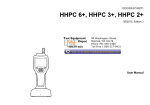
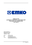
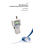
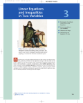
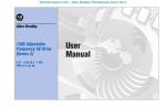
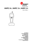
Bulletin 1305 AC Drives
Simple,
Flexible, and
PerformanceRich
Simple, Flexible and
Performance-Rich
The Bulletin 1305 AC drive is a variable speed drive designed to control the speed of three-phase AC
induction motors in a variety of demanding applications where flexibility, performance and ease of use
are essential. The 1305 drive is available with ratings 0.37 to 4 kW (0.5 to 5HP) at 380-460V and 0.37
to 2.2 kW (0.5 to 3HP) at 200-230V.
Simple
Application performance requirements are often met “out of the box” without parameter adjustments.
If parameter adjustments are necessary, these can be easily made using the Human Interface Module
(HIM). This operator interface has large, positive feedback keys that allow for easy programming, but
is small enough to carry in your pocket.
Flexible
The 1305 AC drive has a wide range of parameters which can be set to meet the requirements of
many diverse applications. The standard SCANport™ communications link permits simple connections
to a variety of communication peripherals including RS232/422/485, DeviceNet™, Remote I/O, and
Flex™ I/O. The 1305 AC drive can connect to ControlNet™ and other networks via Allen-Bradley Flex I/O
to SCANport communication module. With the addition of a SCANport expander, multiple devices can
communicate with a 1305 AC drive.
Performance-Rich
High Torque
Simple does not imply reduced
performance. The 1305 AC drive is
capable of producing high torque
across a wide speed range.
Fast Acceleration
Fast acceleration times mean more
cycles per minute, and translates into
increased revenue.
Performance Testing
The 1305 AC drive is tested on a
dynamometer at Allen-Bradley’s
development facility.
Hybrid Current Limit
The hybrid current limit function utilizes both firmware and hardware control to minimize the
possibility of trips during shock loads, fast accelerations, constant speed operation and deceleration.
IR Compensation
The IR compensation function increases power to the motor when it is needed most.
Slip Compensation
The 1305 AC drive features Slip Compensation, which provides tighter speed control during
load changes.
2
Product Positioning
Offering the industry’s broadest range of horsepower, functionality and features, Allen-Bradley has a
drive which can help meet your requirements. From small stand-alone applications to massive,
integrated systems, our full line of industrial drives provides the flexibility, reliability and precise
motor control necessary to keep your business moving at the right speed. The 1305 drive has
advanced technology in a rugged, compact package that offers the proper blend of performance and
functionality to make it a market leader.
GENERAL PURPOSE
HIGH PERFORMANCE DRIVES
COST/PERFORMANCE
Human Interface Module
(HIM)
1336 FORCE™ Drive
1336 IMPACT™ Drive
The Human Interface Module
(HIM) features a backlit LCD
display and computer-like
programming keys. Easy-to-read
messages indicating drive status
and diagnostic information allow
the user to quickly react to
changing process conditions.
The HIM can be used with other
SCANport products including
1336 FORCE™, 1336 IMPACT™
and 1336 PLUS drives.
1336 PLUS Drive
1305 Drive
Bridging the Gap
160 Smart Speed Controller™
DEFINITE PURPOSE DRIVES
FUNCTIONALITY
The performance and
functionality of the Bulletin 1305
AC drive bridges the gap
between Definite Purpose and
General Purpose/High
Performance drives.
3
Small, Yet Feature-Rich
Design Features
Interface/Communications
• Human Interface Module with
backlit LCD Display.
• Foreign language compatibility.
• Multiple communication options.
Software
• IR compensation.
• Inherent braking.
• Hybrid Current Limit.
• Slip compensation.
• Extensive parameter list.
Physical
• Intelligent power modules using IGBT
technology.
• CE marked for all applicable European
directives:
Emissions EN55011 Class B
Immunity EN50082-1
EN50082-2
• Standard IP30 (NEMA Type 1) enclosure.
• Optional Configured IP42 (NEMA Type 1) or
IP65 (NEMA Type 4/12).
• Hinged front cover for easy access to the
power and control wiring.
• Built-in protective features.
Control
• Configurable for either two-wire
or three-wire control.
• 0 – 10V DC speed input.
• Remote potentiometer input.
• 4 – 20 mA analog speed input.
• Two programmable outputs
(1 relay, 1 transistor).
• Programmable 0 – 10 volt analog output.
4
Hybrid Current Limit
The hybrid current limit function utilizes both
firmware and hardware control to minimize the
possibility of trips during shock loads, fast
accelerations, constant speed operation and
deceleration.
Inherent Braking
The inherent braking capability of the drive
provides fast deceleration times by using a
patented software-driven regulator to control
the deceleration ramp. For many applications,
this helps:
• Reduce the requirement for external
braking resistors.
• Save valuable panel space.
• Lower installation costs.
Frequency (Hz)
Do not let the compact size fool you. Bulletin
1305 AC drives offer many features to enhance
the performance of your application.
0
1
2
3
4
Bulletin 1305 Decel Ramp Control
Typical Decel Control
5
Time
Built-in Protective Features
• Motor overload protection – UL listed and CSA
certified as a motor overload protective device
and designed to meet IEC and VDE standards
for motor overload protection. No external
overload protection is required for single motor
applications. This saves valuable panel space
and reduces the total installation cost.
• Short circuit on the output phases.
• Ground fault during power up of motor.
• Over temperature due to improper ventilation.
1305 AC Drive Performance:
Real Test Data
“Trip-Free” Operation
Acceleration
Current
Speed
Accelerating @ 150% load, 0.1 sec.
acceleration setting – note smooth motor
speed response
• Fast acceleration.
• More cycles per hour.
Torque
To help avoid nuisance tripping
and improve process efficiency,
the drive is designed with control
logic that will:
• Regulate acceleration and
deceleration ramp rates to
help prevent overcurrent and
overvoltage trips.
• Limit output current to 200%
of drive output rating during
intermittent overload
conditions.
Quiet Operation
Bulletin 1305 AC drives use IGBT
(insulated gate bi-polar
transistor) technology to provide
faster switching of the output
transistors compared to
conventional bi-polar transistors.
The carrier frequency is
adjustable in 100 Hz increments
to help minimize audible noise
and reduce mechanical
resonance.
Torque
Torque performance is exceptional (test
progressively loads motor from at speed,
no load condition to a stall)
• When machine cycle requires high torque at
low speeds, the 1305 AC drive can deliver.
• Torque performance is maintained across the
entire speed range.
Shock Load
Dynamic response to shock load
Current
Speed
Load Applied
Here
• Even with shock loads demanding 150%
torque, the 1305 AC drive maintains control
of current and speed.
Torque
5
Integrated Automation
Drive Software for
Windows™
DriveExplorer™ Software is an
online programming tool that
provides a fast, simple, costeffective method to configure
and monitor drive and
communication adapter
parameters. With an easy
Windows “Explorer-like”
interface, you have the ability to
create custom parameter views
by using the cut/copy/paste or
drag & drop functionality.
DriveExplorer is compatible
with Microsoft Windows
95/98/NT/CE ™.
The Bulletin 1305 AC drive doesn't just provide connectivity to various communication networks and
controllers but does much more. It becomes a key control strategy in an integrated automation system.
The diagram below illustrates Allen-Bradley products and options that provide this high level
of integration.
DH-485
Remote I/O
DeviceNet
ControlNet
Other
RS232/422/DF1
SCANport
DriveTools32™ Software suite for
Microsoft® Windows 95/98/NT ™
is designed for online and offline
programming, troubleshooting,
and maintaining Allen-Bradley
AC and DC drive products. Easyto-use menus, dialogs and
graphic displays help you quickly
start-up your Allen-Bradley drive
product. Powerful diagnostic
features simplify troubleshooting
drives and drive systems.
ESC
1203-FB1 (Base) and 1203-FM1 (Module)
for Flex I/O (Control and Status Only)
1203-GD2/GK2
Serial Comm Module
22
1203-CN1
ControlNet
Module
1203-GD1/GK1
Remote I/O Module
SEL
JOG
DriveTools32™
1203-GU6
Enhanced
DeviceNet
Module
1203-SM1
SLC/SCANport Module
SCANport
Port 2
Port 4
Port 1 or 3
Port 5
1203-SG4
4-Port Splitter
or
1203-SG2
2-Port Splitter
6
HIMs
1201-HA2/HAP/HA1
Operator Interface That
Makes Sense
Customized Display for
Your Process
The drive can display a process
variable in “User Definable Units”.
A parameter, such as output
frequency, can be converted and
scaled to display process variables
such as RPMs, liters per minute or
gallons per hour. This descriptive
display makes the drive easier to
use and an integral part of the
automation system.
HIM – Digital Speed
Control
Provides digital speed control
and programming functionality
from the local panel.
HIM – Analog Speed
Potentiometer
Take Hold of the New Features Available with the Human Interface Module
Provides analog speed control
and programming functionality
from the local panel.
Designed with simplicity in mind, the Human Interface Module (HIM) features a two-line, sixteencharacter backlit LCD display and computer-like programming keys. Easy-to-read messages indicating
drive status and diagnostic information allow the user to quickly react to changing process conditions.
Available in IP30 (NEMA Type 1) and IP66 (NEMA Type 12/UL Type 4X – Indoor) designs.
Other features include:
• Upload/download capability: Resident memory
allows for storage of two complete drive
parameter profiles, saving time programming
multiple drives.
• Fault queue: View the last four faults in the
Control Status mode without going into the
Program or Display mode.
• Search: Allows user to search a parameter
profile to determine which features are no
longer at factory default values.
• Saving menus for power-up:
Can be programmed to power up to a
variety of process displays (i.e. RPM,
Feet-per-minute, etc.).
• Immediate fault display: If a fault occurs,
fault message appears regardless of what
mode is in use.
• Commonality: The HIM can be used with other
SCANport products including 1336 PLUS,
1336 IMPACT and 1336 FORCE AC drives.
• Bit Enumeration: User can scroll and view
a text description of each bit in a binary
parameter without using a look-up table
for identification.
• HIMs: Can be drive mounted, panel mounted or
hand held with a cable connection.
• Changing digits of parameters and passwords:
Increment or decrement individual parameter
digits to save programming time.
HIM – Programmer Only
Provides programming
functionality from the
local panel.
HIM – NEMA 12/UL4X –
Indoor
• HIMs are available in NEMA
12/UL4X – Indoor
construction for remote panel
mounting.
• Available as digital speed
control and programmer only.
7
Configured to
Meet Your Needs
Configured Drives Program
The Configured Drives Program allows you to order specifically configured drives packages that exceed
the offerings of standard drive products. The expanded options list includes control, communications,
power, packaging and documentation. Packaging is available in IP42 (NEMA Type 1) or IP65 (NEMA
Type 4/12) enclosures.
The capabilities of this program range from supplying simple, commonly requested pre-engineered
options to more complex, specifically engineered requirements.
All Allen-Bradley Configured Drives are supplied with complete, order-specific drawings and
standard instruction manuals. Special documentation and test requirements will also be supplied
as requested. Support publications are available to assist in custom configuration and ordering
special drive packages.
Configured 1305 drive
Drives Are an Integral Part of CENTERLINE™ Motor Control Centers
Not only do we install thousands of drives in Motor Control Centers every year, but they’ve been in our
Motor Control Centers for over a decade. In fact, one-third of all Allen-Bradley Motor Control Centers
include drive units.
Motor Control Plug-In Unit with 5 HP
Bulletin 1305 AC drive. MCC sections can
have up to four 1305 drive units.
Bulletin 1305 drive units
installed
in an Allen-Bradley CENTERLINE
Motor Control Center.
8
Use An Allen-Bradley Motor with 1305 AC Drives
Allen-Bradley motors provide improved operating efficiency. However, the complete answer goes
further than this. Since the motor voltage waveshape is determined by both the drive and motor,
optimum performance is achieved when the motor and drive are matched to each other. The
Allen-Bradley Bulletin 1329R motor is matched in its electrical design to the 1305 drive. This
improves performance and helps provide longer, cooler motor operation.
Not Every Motor is Optimized for Use on Adjustable Frequency Drives
Inverter rated motors available on the market today will operate satisfactorily with a 1305 drive.
However, using an Allen-Bradley motor with your 1305 drive removes the guesswork and helps
provide a complete solution from a single source you can trust.
OEM Needs Are Met with the 1305 AC Drive
• Proven product – time tested.
Allen-Bradley Motors
• Meets demands of cyclic loads.
• “Trip-free” operation.
• Programming commonality with other Allen-Bradley drives.
• HIM Upload/Download function for programming multiple drives.
• Communications – RS232, 422, 485, Remote I/O, DeviceNet, Flex I/O, Other.
• Feature-rich for flexibility.
Monorail Installation
• Slip Compensation.
• CE marked for all applicable European directives
Emissions
Immunity
EN55011 Class B
EN50082-1
EN50082-2
• Flexible firmware for special applications.
Note: The Configured Drives program shown on these pages is typical of North America.
Other locations should contact their local Rockwell Automation office for availability of
similar products.
Washing Machine Application
9
Transportation
Applications
• Conveyors
With the advancements in AC drives technology
comes increased reliability and performance. The
Bulletin 1305 AC drive is a proven solution for a
multitude of applications including, but not
limited to, those shown on this page.
Consumer
Conveyors
• Monorails
• Material Handling
• Storage and Retrieval
Systems
• Material Handling
• Conveyors
Bulletin 1305 AC drives provide the performance
demanded in high-speed conveyor applications.
• Labeling
• Packaging
• Bottling
• Filling
• Screw Conveyor
Monorail
• Pumps (Centrifugal and
Positive Displacement)
Monorails are used in installations where
downtime can cost serious money. The 1305 AC
drive’s performance-rich design has gained the
trust of industrial users.
• Mixers
• Ovens
• Pharmaceutical Process
Metals
• Lathe
• Vertical Milling Machine
• Small Lifts
• Mechanical Hoists
• Grinders
Petrochemical and
Mining
Packaging
Varying load demands occurring with food
processing equipment, such as packaging or
bottling lines, are easily handled with the
Bulletin 1305 AC drive.
• Mixers
• Pumps/Fans
• Grinders
• Injection Molding
Pulp and Paper
• Converting
Other Applications
• Mixing
The drive applications are endless. Bulletin 1305
AC drives offer smart solutions for many other
applications, such as grinders.
• Flow Pumps
10
Drive Product Selection
The Bulletin 1305 is a microprocessor controlled adjustable frequency drive designed for reliable control of
three-phase induction motors. The drive produces a three-phase, PWM, adjustable frequency output to vary the
motor speed. The drive output voltage is a function of output frequency and is adjustable to meet motor
parameters so that optimum motor performance can be obtained.
For further information see:
Product Selection
Accessories
Specifications
Dimensions
Parameter List
Configured Drives Program
Page 11
Page 12
Page 15
Page 17
Page 18
Page 20
Bulletin 1305 Drives with Blank Front Panel (Cat. No. 1201-HAB) Installed as Standard
Three-Phase Input
Voltage
Rating
200-230V
50/60 Hz
380-460V
50/60 Hz
AC Drive
Cat. No. 1305-AA04A-HA1
HP
0.5
0.75
1
2
3
0.5
0.75
1
2
3
5
kW
0.37
0.55
0.75
1.5
2.2
0.37
0.55
0.75
1.5
2.2
4.0
Output
Current Rating
2.3A
3.0A
4.5A
8.0A
12.0A
1.3A
1.6A
2.3A
4.0A
6.0A
9.0A
Single-Phase Input
Output
HP
kW
Current Rating
–
–
–
0.5
0.37
2.3A
0.75
0.55
3.0A
1
0.75
4.5A
2
1.5
8.0A
–
–
–
–
–
–
–
–
–
–
–
–
–
–
–
–
–
–
IP30 (NEMA Type 1)
Catalog Number ➀➁
1305-AA02A
1305-AA03A
1305-AA04A
1305-AA08A
1305-AA12A
1305-BA01A
1305-BA02A
1305-BA03A
1305-BA04A
1305-BA06A
1305-BA09A
➀ 1305 drives include English text display. A second language text
display may be added, if required. To order a second language,
add the appropriate letter code.
Language
German
Spanish
Italian
French
Letter
DE
ES
IT
FR
➁ To order a drive with a Human Interface Module (HIM) installed,
add the appropriate suffix. Note: Blank panel is included as part
of base Cat. No.
Human Interface Module (HIM)
Analog Speed Potentiometer
Digital Up-Down Speed Control
Programmer Only
Suffix
-HA1
-HA2
-HAP
11
Accessories
Bulletin 1201 Operator Interface Devices
Human Interface Module
Catalog Number
HIM (Human Interface Module
IP66
IP30
(NEMA Type 12)
Description
(NEMA Type 1) UL Type 4X Indoor
Programmer/Analog Speed Operator 1201-HA1
–
Programmer/Digital Speed Operator 1201-HA2
1201-HJ2
Programmer Only
1201-HAP
1201-HJP
Drive Blank Cover
1201-HAB
–
Door Mount Bezel Kit
1201-DMA
–
GPT (Graphic Programming Terminal)
IP30
(NEMA Type 12)
–
1201-HJ3E
1201-HJPE
–
–
Hand Held
–
1201-HH3E
1201-HHPE
–
–
Graphic Programming
Terminal
Bulletin 1202 Port Cables
Port Cable
Length
0.33 Meter (1.1 Feet)
1 Meter (3.3 Feet)
3 Meter (9.8 Feet)
9 Meter (29.5 Feet)
Male-Male for Port 1 (Front)
1202-C03
1202-C10
1202-C30
1202-C90
Male-Female for Port 2 (Side)
1202-H03
1202-H10
1202-H30
1202-H90
Bulletin 1203 Port Splitters
2 Port Splitter Cable
Description
2 Port Cable
2 Port Module
4 Port Module
Catalog Number
1203-S03
1203-SG2
1203-SG4
2 Port Splitter Module
Bulletin 1203 Communication Modules
Communication Module
Flex I/O Communication
Module and Terminal Base
12
Description
Remote I/O
SLC (each connects up to 3 drives)
RS232/422/485
(DF1 & DH485 Protocols)
DeviceNet
Enhanced DeviceNet
ControlNet
Flex I/O
(each connects up to 2 drives)
Required Power
24V DC
115V AC
1203-GK1
1203-GD1
–
–
1203-GK2
1203-GD2
None
–
1203-SM1
–
Required
Terminal Base
–
–
–
1203-GK5
1203-GU6
1203-CN1
–
–
–
–
1203-FM1
–
–
–
1203-FB1
–
–
–
–
Accessories
Bulletin 1203 Computer Interfaces
Description
Smart Serial Converter
(includes SFC)
Serial Flash Cable
Smart Serial Converter
with Serial Flash Cable
Use With . . .
Drive
Catalog Number
1203-SSS
SLC Module
1203-SFC
Enhanced DeviceNet Module
ControlNet Module
1305 Dynamic Brake Kits
Description
When connected to a Bulletin 1305 drive, this kit helps provide additional
AC Dynamic Braking Torque. (Not available for 1305-AA02, 1305-AA03, or
1305-AA04.)
Dynamic Brake
Use With . . .
1305-AA08
1305-AA12
1305-BA01
1305-BA02
1305-BA03
1305-BA04
1305-BA06
1305-BA09
IP 30
(NEMA Type 1)
Catalog Number
1305-KAA12
1305-KAA12
1305-KBA03
1305-KBA03
1305-KBA03
1305-KBA06
1305-KBA06
1305-KBA09➀
Bulletin 1321 Line Reactor
Description
Iron Core, 600V, Class H
insulation, 115 degree C
rise, copper wound, 50/60
Hz, terminal blocks, UL,
CSA, CE.
Line Reactor
3% Impedance
IP00
Use With . . . (Open Style)
1305-AA02
1321-3R4-B
1305-AA03
1321-3R4-A
1305-AA04
1321-3R4-A
1305-AA08
1321-3R8-A
1305-AA12
1321-3R12-A
1305-BA01
1321-3R2-B
1305-BA02
1321-3R2-A
1305-BA03
1321-3R2-A
1305-BA04
1321-3R4-B
1305-BA06➁ 1321-3R4-B➁
1305-BA06
1321-3R8-B
1305-BA09➁ 1321-3R8-B➁
1305-BA09
1321-3R12-B
IP10
(NEMA Type 1)
1321-3RA4-B
1321-3RA4-A
1321-3RA4-A
1321-3RA8-A
1321-3RA12-A
1321-3RA2-B
1321-3RA2-A
1321-3RA2-A
1321-3RA4-B
1321-3RA4-B➁
1321-3RA8-B
1321-3RA8-B➁
1321-3RA12-B
5% Impedance
IP00
(Open Style)
1321-3R4-C
1321-3R4-B
1321-3R4-B
1321-3R8-B
1321-3R12-B
1321-3R2-C
1321-3R2-B
1321-3R2-B
1321-3R4-C
1321-3R4-C➁
1321-3R8-C
1321-3R8-C➁
1321-3R12-C
IP10
(NEMA Type 1)
1321-3RA4-C
1321-3RA4-B
1321-3RA4-B
1321-3RA8-B
1321-3RA12-B
1321-3RA2-C
1321-3RA2-B
1321-3RA2-B
1321-3RA4-C
1321-3RA4-C➁
1321-3RA8-C
1321-3RA8-C➁
1321-3RA12-C
Bulletin 1204 Reflected Wave Reduction Device
Reflective Wave
Reduction Devices
Description
Connected between the drive and any standard motor to
provide a simple solution to help protect motors from
premature failure due to reflected wave impulses. 4kHz
carrier frequency maximum. Mounts book style or stack style
near the drive. The 1204-RWR2-09-C has the same footprint
as the 1305-BA09A when stack style mounted. The 1204RWR2-09-B has the same footprint as all the other 460V
1305 drives when stack style mounted.
Use With . . .
All 460V 1305 Drives book style
mounted, or 1305-BA01A, 1305BA02A, 1305-BA03A, 1305BA04A, 1305-BA06A stack style
mounted
1305-BA09A Drives stack style
mounted only
IP 30
(NEMA Type 1)
1204-RWR2-09-B
1204-RWR2-09-C
➀ For use with Series C or B Drives Only. DO NOT use with Series A Drives.
➁ Input reactor only.
13
Accessories
Bulletin 1204 Terminator
Description
Connected to any standard motor to provide a simple solution in helping
protect motors from premature failure due to reflected wave impulses. An
integral connection cable is provided to simplify installation. Mounts near
the motor. If you plan to operate your system at carrier frequency above
2kHz, consult the factory.
Use with . . .
1305-BA03A
1305-BA04A
1305-BA06A
1305-BA09A
IP30
(NEMA Type 1)
1204-TFA1➀
1204-TFA1 or TFB2➀
1204-TFA1 or TFB2➀
1204-TFA1➀
Motor Terminator
Bulletin 1321 Isolation Transformer
Description
230V/230V or 460V/460V, Delta primary/Wye secondary, Class H
insulation, 150 degree rise, aluminum wound, 60 Hz, ±5% taps, (1) N.C.
thermostat per coil, UL, CSA.
Isolation Transformer
Use with . . .
1305-AA02
1305-AA03
1305-AA04
1305-AA08
1305-AA12
1305-BA01
1305-BA02
1305-BA03
1305-BA04
1305-BA06
1305-BA09
IP23
(NEMA Type 1)
1321-3T005-AA
1321-3T005-AA
1321-3T005-AA
1321-3T005-AA
1321-3T005-AA
1321-3T005-BB
1321-3T005-BB
1321-3T005-BB
1321-3T005-BB
1321-3T005-BB
1321-3T007-BB
CE Conformance ➁
Filters
A EMC filter is required for CE Conformance. A Metal Conduit Plate
(see below) is also required.➁
Line Filter
Metal Conduit Plate
Use with . . .
1305-AA02
1305-AA03
1305-AA04
1305-AA08
1305-AA12
1305-BA01
1305-BA02
1305-BA03
1305-BA04
1305-BA06
1305-BA09
Metal Conduit Plates
A Metal Conduit Plate is required for CE Conformance. May also be
1305-AA02
used for non-CE applications where a more rugged conduit termination 1305-AA03
is needed.➁
1305-AA04
1305-AA08
1305-AA12
1305-BA01
1305-BA02
1305-BA03
1305-BA04
1305-BA06
1305-BA09
➀ See Bulletin 1204 Motor Terminator Brochure (publication 1204-1.0) for proper selection.
➁ Installation guidelines called out in Appendix D of the 1305 User's Manual (publication 1305-5.2) must be adhered to.
14
Catalog Number
1305-RFB-5-A
1305-RFB-5-A
1305-RFB-5-A
1305-RFB-8-B
1305-RFB-12-C
1305-RFB-8-B
1305-RFB-8-B
1305-RFB-8-B
1305-RFB-8-B
1305-RFB-8-B
1305-RFB-12-C
1305-MP-05-A
1305-MP-05-A
1305-MP-06-A
1305-MP-08-B
1305-MP-12-C
1305-MP-08-B
1305-MP-08-B
1305-MP-08-B
1305-MP-08-B
1305-MP-08-B
1305-MP-12-C
Specifications
1305 Drives Rated 200-230V AC
1305 Drives Rated 380-460V AC
-AA02A -AA03A -AA04A -AA08A -AA12A -BA01A -BA02A -BA03A -BA04A
OUTPUT RATINGS
Motor Rating kW (HP)
0.37
0.55
0.75
1.5
2.2
(0.5)
(0.75)
(1)
(2)
(3)
2.3
3.0
4.5
8.0
12.0
Adjustable from 0 Volts to input voltage
0.00 to 400.00 Hz programmable
0.37
(0.5)
1.3
0.55
(0.75)
1.6
0.75
(1)
2.3
1.5
(2)
4.0
-BA06A
-BA09A
2.2
(3)
6.0
4.0
(5)
9.0
Output Current (A)
Output Voltage
Output Frequency (Hz)
INPUT RATINGS
Input Voltage & Frequency 200/230V Three-Phase, 50/60 Hz
380/460V Three-Phase, 50/60 Hz
Operational Range (V)
180-265V
340-500V
Input kVA
0.9
1.3
1.7
3.1
4.6
0.9
1.3
1.7
3.1
4.6
7.0
Power Factor
0.8 (Lagging)
(Displacement)
Efficiency (%)
97.5% (Typical)
Power Dissipation (W)
27
34
46
76
108
21
27
34
52
73
107
ENVIRONMENTAL SPECIFICATIONS
Enclosure
IP30 (NEMA 1) standard
Ambient Temperature
0 to 50 degrees C; optional enclosures: 0 to 40 degrees C.
Storage Temperature
-40 to 70 degrees C
Relative Humidity
0 to 95% (non condensing)
Vibration
1.0 G Operational
Cooling Method
Natural Convection (no fans)
Altitude
Above 1,000 meters (3,300 feet), derate at 6% of drive rated amps per 1000 meters (3,300 feet).
CONTROL INPUTS
Control Input Type
Contact closure (internal 5V supply). DO NOT ground or apply external voltage.
Start
Configurable inputs for 2 or 3 wire control
Stop
Forward/Reverse
Jog
Momentary (non-maintained) input
SW1
Configurable inputs for control of 7 preset speeds and 2 accel/decel times
SW2
SW3
Enable
Interlock input to enable drive operation
External Speed
10k Ohms, 1 Watt
Potentiometer
Analog Input (4 to 20mA) Input lmpedance 250 Ohms (non-isolated), 10 bit resolution
Analog Input (0 to 10 V) Input impedance 100 k Ohms (non-isolated), 10 bit resolution
CONTROL OUTPUTS
Programmable Output 1 Form A Relay Contact: Resistive Rating 115V AC/ 30V DC, 5A; Inductive Rating 115V AC/ 30V DC, 2A
Programmable Output 2 Open Collector (Sink): 24V DC, ±20%, 50 mA maximum. User supplied source voltage.
Analog Output (0-10V DC) Load lmpedance greater than or equal to 4,000 Ohms, 8 bit resolution
PWM AIgorithm
Sine weighted PWM output
Switching Device
IGBT Intelligent Power Module
Three-Phase Output
V/Hz Ratio
Programmable
Carrier Frequency
Adjustable in 100 Hz increments from 2 kHz to 8 kHz. Output current derating applies above 4 kHz.
DC Boost
Adjustable single point or full custom - start and run boost available.
15
Specifications
1305 Drives Rated 200-240V AC
1305 Drives Rated 380-460V AC
-AA02A -AA03A -AA04A -AA08A -AA12A -BA01A -BA02A -BA03A -BA04A -BA06A -BA09A
CONTROL FEATURES
AC Dynamic Braking
Torque➀
W/o External Resistor
With External Resistor
Current Limiting
100%
100%
100%
50%
50%
100%
100%
100%
N/A
N/A
N/A
150%
100%
150%
150%
150%
Trip Free Operation, coordinated for drive and motor protection
Programmable from 20% to 150% of Drive Rated Current
200%, Fixed by hardware, based on Drive Rating. 150% for 60 seconds.
Electronic Overload Protection. adjustable from 20% to 115% (Motor FLA)
Flat response over speed range (no speed compensation)
Speed compensation below 25% of Base Speed
Speed compensation below 50% of Base Speed
0.1 to 3600 seconds, independently set (2 Accel, 2 Decel)
0 to 400 Hz, 7 selections, independently set
0 to 400 Hz
4 modes programmable
0.1 to 3600 seconds
Stops all PWM Output
Applies DC Voltage to the motor for 0 to 150 seconds
Ramps to stop with S-Curve profile
50%
150%
50%
100%
20%
100%
Overload
Motor Protection
Overload Pattern #0
Overload Pattern #1
Overload Pattern #2
Accel/Decel Time(s)
Preset Speeds
Jog Input
Stopping Modes
Ramp to stop
Coast
DC Brake to stop
S-Curve
PROTECTIVE FEATURES
Excessive Temperature
Embedded temperature sensor trips if factory preset level is exceeded.
Over/Under Voltage
DC Bus voltage is monitored
Power Ride Through
Minimum ride through 15ms under nominal conditions
Control Ride Through
Minimum ride through is 0.5 seconds - typical value 2 seconds
Ground Short
Any output short to ground, detected prior to start
Line Voltage Transients
Inherent MOV (varistor) protection
Output Short Circuit
Inherent short circuit protection provided within IPM
PROGRAMMING/COMMUNICATIONS
Hand Held Programming Optional Human Interface Module (HIM can be removed from the Drive)
Type of Annunciation
Parameters displayed in textual form, organized in logical groupings
Type of Display
16 character, 2 line LCD supertwist with backlight
Language Capability
Multiple languages available
Local Controls
3 versions available (digital pot., analog pot. and blank)
Communication Adapters Optional adapters provide Remote I/O, or RS232/422/485/DH485 or RS232/422/485/DF1 capability
MONITORING
Output Frequency (Hz)
Displayed over the entire range of operation with direction indication
Output Voltage (V)
Selectable as a displayed parameter
Output Current (A)
Selectable as a displayed parameter in % or actual value
Output Power (kW)
Selectable as a displayed parameter in % or actual value
DC Bus Voltage (V)
Selectable as a displayed parameter
Frequency Command (Hz) Selectable as a displayed parameter
Process Parameter
Any drive variable can be scaled and definable text can be added up to 8 characters
Drive Temperature
Selectable as a displayed parameter in degees C.
Last Fault
The previous 4 faults can be displayed for troubleshooting
➀ Estimated – actual value will depend on motor characteristics.
16
Specifications
Bulletin 1305 Drive Dimensions
C Max.
C
5.5 (0.22) Dia.
J
D
H
22.5 (0.89) - 4 Plcs.
ESC
B
SEL
E
JOG
G
F
Dimensions are in millimeters (inches) and are not intended for manufacturing purposes. Shipping weights are in kilograms (pounds).
200/230 V
Cat. No.
1305- . . .
AA02A
AA03A
AA04A
380/460 V
Cat. No.
1305- . . .
–
AA08A
BA01A
BA02A
BA03A
BA04A
BA06A
BA09A
–
AA12A
A
Width
120
(4.72)
120
(4.72)
170
(6.69)
B
Height
195
(7.68)
195
(7.68)
195
(7.68)
C
Depth
w/o Pot.
122
(4.80)
140
(5.51)
179
(7.05)
C Max.
Depth
w/ Pot.
127.1
(5.00)
145.1
(5.71)
184.1
(7.25)
D
110
(4.33)
110
(4.33)
160
(6.30)
E
180
(7.09)
180
(7.09)
180
(7.09)
F
9
(0.35)
27
(1.06)
66
(2.60)
G
113
(4.45)
113
(4.45)
113
(4.45)
H
5
(0.20)
5
(0.20)
5
(0.20)
J
7.5
(0.30)
7.5
(0.30)
7.5
(0.30)
Approx.
Ship Wt.
1.6
(3.5)
1.9
(4.2)
3.6
(8.0)
210
(8.27)
195
(7.68)
179
(7.05)
184.1
(7.25)
200
(7.87)
180
(7.09)
66
(2.60)
113
(4.45)
5
(0.20)
7.5
(0.30)
4.2
(9.2)
Bezel Kit (Catalog Number 1201-DMA)
43.1 (1.70)
w/ Analog Pot.
38.0 (1.50)
w/ Digital Pot.
120.0
(4.72)
60.0
(2.36)
15.0 (0.59)
Mounting Hole
22.5 (0.89) Dia.
18.5 (0.73)
ESC
195.0
(7.68)
SEL
155.0
(6.10)
JOG
Mounting Hole
4.5 (0.18) Dia.
17
1305 Parameter List
Parameter Group
Metering
Set Up
Advanced Setup
Frequency Set
18
Parameter Name
Output Current
Output Voltage
Output Power
DC Bus Voltage
No.
54
1
23
53
Units
0.01 Amps
1 Volt
0.01 kW
1 Volt
Minimum
0.00
0
0.00
0
Output Freq
Freq Command
MOP Hertz
Drive Temp
Last Fault
% Output Power
% Output Curr
Input Mode
Freq Select 1
Accel Time 1
Decel Time 1
Base Frequency
Base Voltage
Maximum Voltage
Minimum Freq
Maximum Freq
Stop Select
Current Limit
Overload Mode
Overload Current
Sec Curr Limit
Adaptive I Lim
Minimum Freq
Maximum Freq
Base Frequency
Base Voltage
Break Frequency
Break Voltage
Maximum Voltage
DC Boost Select
Start Boost
Run Boost
PWM Frequency
Analog Invert
4-20 mA Loss Sel
Stop Select
DC Hold Time
DC HoId Volts
DB Enable
Motor Type
Compensation
Freq Select 1
Freq Select 2
Jog Frequency
Prst/2nd Accel
Upper Presets
Accel Time 2
Decel Time 2
Preset Freq 1
Preset Freq 2
Preset Freq 3
Preset Freq 4
Preset Freq 5
Preset Freq 6
Preset Freq 7
Skip Freq 1
Skip Freq 2
Skip Freq 3
Skip Freq Band
MOP Increment
Analog Filter
66
65
42
70
4
3
2
21
5
7
8
17
18
20
16
19
10
36
37
38
141
149
16
19
17
18
49
50
20
9
48
83
45
84
81
10
12
13
11
41
52
5
6
24
26
72
30
31
27
28
29
73
74
75
76
32
33
34
35
22
144
0.01 Hz
0.01 Hz
0.01 Hz
1 degree C.
Numeric
1%
1%
Text
Text
0.1 Seconds
0.1 Seconds
1 Hz
1 Volt
1 Volt
1 Hz
1 Hz
Text
1%
Text
0.1 Amps
1%
Text
1 Hz
1 Hz
1 Hz
1 Volt
1 Hz
1 Volt
1 Volt
Text
1 Volt
1 Volt
0.1 kHz
Text
Text
Text
0.1 Seconds
1 Volt
Text
Text
Text
Text
Text
0.1 Hz
Text
Text
0.1 Seconds
0.1 Seconds
0.1 Hz
0.1 Hz
0.1 Hz
0.1 Hz
0.1 Hz
0.1 Hz
0.1 Hz
1 Hz
1 Hz
1Hz
1 Hz
1 Hz/Second
Text
0.00
0.00
0.00
0
0
0
0
--0.0
0.0
40
25% of DRV
25% of DRV
0
40
-20% of DRC
-20% of DRC
0
-0
40
40
25% of DRV
0
0
25% of DRV
-0
0
2.0
---0.0
0
-----0
--0.0
0.0
0.0
0.0
0.0
0.0
0.0
0.0
0.0
0
0
0
0
0.00
--
Maximum
Two times drive output current
Maximum Voltage
Two times rated drive output power
410 - 230V Drive
815 - 460V Drive
Maximum Frequency
+400.00
400.00
100
Max. Fault Number
200% Drive Rated Power
200% of Rated Drive Output Current
--3600.0
3600.0
400
100% of Max. Drive Rated Volts
110% of Max. Drive Rated Volts
120
400
-150% of Drive Rated Current (DRC)
-115% of Drive Rated Current (DRC)
150% of Drive Rated Current (DRC)
-120
400
400
100% of Max. Drive Rated Volts
120
50% of Maxi. Drive Rated Volts
110% of Max. Drive Rated Volts
-25% of Max. Drive Rated Volts
25% of Max. Drive Rated Volts
8.0
---150.0
25% of Maximum Drive Rated Volts
------400.0
--3600.0
3600.0
400.0
400.0
400.0
400.0
400.0
400.0
400.0
400
400
400
15
255.00
--
Factory Setting
-----0.00
-----Three Wire
Adapter 1
10.0
10.0
60
100% of Max. DRV
100% of Max. DRV
0
60
Ramp
150% of DRC
No Derating
115% of DRC
0
Enabled
0
60
60
100% of Max. DRV
30
Drive Size Depend.
100% of Max. DRV
Break Point
Drive Size Depend.
0
4.0
Disabled
Stop/Fault
Ramp
0.0
0
Disabled
Induc/Reluc
Comp.
Adapter 1
Remote Pot
10.0
Preset
Disabled
5.0
5.0
10.0
20.0
30.0
40.0
50.0
60.0
0.0
400
400
400
0
1.00
100%
1305 Parameter List
Parameter Group
Feature Select
Output Config
Faults
Diagnostics
Masks
Owners
Adapter I/0
Process Display
Parameter Name
Run On Power Up
Reset/Run Tries
Reset/Run Time
S Curve Enable
S Curve Time
Language
Cable Length
Rated Slip
Slip Comp Adder
IR Comp %
Output 1 Config
Output 2 Config
Analog Out Sel
Above Freq Val
Above Curr Val
Fault Buffer 0-3
Clear Fault
Cur Lim Trip En
Line Loss Fault
Flt Clear Mode
Drive Command
Drive Status
Drive Alarm
Input Status
Freq Source
Freq Command
Drive Direction
Motor Mode
Power Mode
Drive Type
Firmware Ver
Output Pulses
Drive Temp
Set Defaults
Logic Mask
Direction Mask
Start Mask
Jog Mask
Reference Mask
Accel Mask
Decel Mask
Fault Mask
MOP Mask
Local Mask
Stop Owner
Direction Owner
Start Owner
Jog Owner
Reference Owner
Accel Owner
Decel Owner
Fault Owner
MOP Owner
Local Owner
Data In A1, A2
Data In B1, B2
Data In C1, C2
Data In D1, D2
Data Out A1, A2
Data Out B1, B2
Data Out C1, C2
Data Out D1, D2
Process Par
Process Scale
Process Text 1-8
No.
14
85
15
57
56
47
143
146
148
147
90
91
25
77
142
86-89
51
82
40
39
58
59
60
55
62
65
69
43
44
61
71
67
70
64
92
94
95
96
97
98
99
100
101
93
102
103
104
105
106
107
108
109
110
137
111, 112
113, 114
115, 116
117, 118
119, 120
121, 122
123, 124
125, 126
127
128
129-136
Units
Text
Numeric
0.1 Seconds
Text
0.1 Seconds
Text
Text
0.1 Hz
0.01 Hz
1%
Text
Text
Text
1 Hz
1%
Numeric
Text
Text
Text
Text
Byte
Word
Byte
Byte
Text
0.01 Hz
Text
Text
Text
Numeric
Numeric
1 Cycle
1 degree C.
Text
Byte
Byte
Byte
Byte
Byte
Byte
Byte
Byte
Byte
Byte
Byte
Byte
Byte
Byte
Byte
Byte
Byte
Byte
Byte
Byte
Numeric
Numeric
Numeric
Numeric
Numeric
Numeric
Numeric
Numeric
Numeric
Numeric
ASCII Text
Minimum
-0
0.5
-0.0
--0.0
0.00
0%
---0
0% of DRC
----------0.00
-----0
0
---------------------0
0
0
0
1
1
1
1
1
-327.68
--
Maximum
-9
30.0
--300.0
--5.0
5.00
150%
---400
150% of Drive Rated Current
----------400.00
-----65535
100
---------------------149
149
149
149
149
149
149
149
149
+327.67
--
Factory Setting
Disabled
0
1.0
Disabled
0.0
Appropriate Lang.
Short
2.0
-Drive Size Depend.
Faulted
Running
Frequency
0
0% of DRC
-Ready
Default Run
F03 Enable
Enabled
-----0.00
Forward
------Ready
01111111
01111111
01111111
01111111
01111111
01111111
01111111
01111111
01111111
01111111
----------0
0
0
0
1
1
1
1
1
1.00
?
19
Configured Drives Program
1305 Configured Catalog Number Explanation
1305
–
AA02AC
Bulletin Number
Rating-Enclosure
(must be specified)
–
HA1C
Human Interface
(optional) ➀
–
GD1C
Communication Card
(optional) ➀
–
CB
Remaining Options
(as/if required) ➀
Configured Product Selection
Constant or Variable Torque Drive, English/English Language Module and enclosure.
Drive Rating
Input Voltage
208V AC
230V AC
380V AC
480V AC
Nominal
kW (HP)
0.37 (0.5)
0.55 (0.75)
0.75 (1)
1.5 (2)
2.2 (3)
0.37 (0.5)
0.55 (0.75)
0.75 (1)
1.5 (2)
2.2 (3)
0.37 (0.5)
0.55 (0.75)
0.75 (1)
1.5 (2)
2.2 (3)
4.0 (5)
0.37 (0.5)
0.55 (0.75)
0.75 (1)
1.5 (2)
2.2 (3)
4.0 (5)
Drive
Amps
2.3
3.0
4.5
8.0
12.0
2.3
3.0
4.5
8.0
12.0
1.3
1.6
2.3
4.0
6.0
9.0
1.3
1.6
2.3
4.0
6.0
9.0
Bypass
Amps➅
2.3
3.0
4.2
8.0
10.0
2.3
3.0
4.2
8.0
10.0
1.0
1.6
2.3
4.0
6.0
9.0
1.0
1.6
2.3
4.0
6.0
9.0
IP42
(NEMA Type 1)
General Purpose
HA02AC
HA03AC
HA04AC
HA08AC
HA12AC
AA02AC
AA03AC
AA04AC
AA08AC
AA12AC➂
NA01AC
NA02AC
NA03AC
NA04AC
NA06AC
NA09AC
BA01AC
BA02AC
BA03AC
BA04AC
BA06AC➃
BA09AC➄
IP65
(NEMA Type 4/12➁)
Resist Water, Dust
HA02FC
HA03FC
HA04FC
HA08FC
HA12FC
AA02FC
AA03FC
AA04FC
AA08FC
AA12FC➂
NA01FC
NA02FC
NA03FC
NA04FC
NA06FC
NA09FC
BA01FC
BA02FC
BA03FC
BA04FC
BA06FC➃
BA09FC➄
➀ As many valid options as required may be strung together with a dash between each option code number.
➁ If a Door Mounted Human Interface Module is supplied, the enclosure will no longer meet NEMA Type 4, but it will meet IP65 qualifications for watertight indoor
applications.
➂ When operating the drive in an ambient temperature at or near the maximum operating temperature (40 degrees C.), the following derating guidelines are
recommended to guard against overheating (depending on application and operating conditions): At 230V input voltage, output current is 9.6A for three-phase and
6.8A for single-phase.
➃ When operating the drive in an ambient temperature at or near the maximum operating temperature (40 degrees C.), the following derating guidelines are
recommended to guard against overheating (depending on application and operating conditions): At 415V input voltage, output current is 5.3A. At 460V input
voltage, output current is 4.8A.
➄ When operating the drive in an ambient temperature at or near the maximum operating temperature (40 degrees C.), the following derating guidelines are
recommended to guard against overheating (depending on application and operating conditions): At 415V input voltage, output current is 8.4A. At 460V input
voltage, output current is 7.6A.
➅ When Bypass is ordered, the drive system is rated to the lower of the drive rating or thermal overload relay rating (as noted by Bypass Amps).
20
Configured Drives Program
Factory Installed Options
Language Modules
Description
English/English
English/German
English/Spanish
English/Italian
English/French
Option Code
Standard
-DEC➀
-ESC➀
-ITC➀
-FRC➀
Can Not be Used With . . .
ESC, FRC, ITC
DEC, FRC, ITC
DEC, ESC, FRC
DEC, ESC, ITC
Option Code
-CB
-DS
Can Not be Used With . . .
DS
CB
Option Code
-BM➁
Can Not be Used With . . .
–
Option Code
-CP
Can Not be Used With . . .
–
Power Disconnecting Means
Description
Circuit Breaker
Fused Disconnect Switch (Class J)
Drive Bypass Operation
Description
Bypass, Manual
Control Power
Description
Control Power Transformer, 50VA
Human Interface Modules, Door Mounted
Description
IP 42 (NEMA Type 1) Bezel Mount
Programmer Only
Programmer/Control with Analog Potentiometer
Option Code
Can Not be Used With . . .
-HAPC
-HA1C
Programmer/Control with Digital Potentiometer
-HA2C
HA1C, HA2C, HJPC, HJ2C, IP 65 or NEMA Type 4/12 Enclosures
D13, D17, D19, D32, D61, HA2C, HAPC, HJ2C, HJPC, IP65 or
NEMA Type 4/12 Enclosures
D13, D17, D19, D32, D61, HA1C, HAPC, HJ2C, HJPC, IP65 or
NEMA Type 4/12 Enclosures
IP 65 (NEMA Type 12)
Programmer Only
Programmer/Control with Digital Potentiometer
-HJPC
-HJ2C
IP 65 (NEMA Type 4)
Not Available
HAPC, HA1C, HA2C, HJ2C, NEMA Type 1 or 4 Enclosures
D13, D17, D19, D32, D61, HA1C, HA2C, HAPC, HJPC, NEMA Type
1 or 4 Enclosures
Communication and Control Interface Modules
Description
Single Point Remote I/O
RS232/422/485, DF1 and DH485 Protocol
24V DC Interface Card with Relay
120V AC Interface Card with Relay
Option Code
-GD1C➁
-GD2C➁
-LTR24➄
-LTR120➄
Can Not be Used With . . .
GD2C
GD1C
LTR120
LTR24
Option Code
-D13➂➃
-D17➂➃
-D19➂➃
-D32➃
-D61➃
Std. w/Option BM
Can Not be Used With . . .
D17, D19, HA1C, HA2C, HJ2C
D13, D19, HA1C, HA2C, HJ2C
D13, D17, HA1C, HA2C, HJ2C
HA1C, HA2C, HJ2C
HA1C, HA2C, HJ2C
Operator Devices, Door Mounted
Description
Hand/Off/Auto (Start/Stop/Speed) Selector Switch
Start and Stop Pushbuttons
Start, Stop and Jog Pushbuttons
Forward/Reverse Selector Switch
Speed Potentiometer, 1-Turn
Drive/Off/Bypass Selector Switch
21
Configured Drives Program
Pilot Lights, Door Mounted - Choose Only One
Description
Drive Run (White)
Drive Fault (Red)
At Speed (Amber)
Alarm (Red)
Above Current (Amber)
Above Frequency (Amber)
➀
➁
➂
➃
➄
Option Code
-D35➁
-D36➁
-D31➁
-D37➁
-D38➁
-D39➁
Can Not be Used With . . .
D31, D36, D37, D38, D39
D31, D35, D37, D38, D39
D35, D36, D37, D38, D39
D31, D35, D36, D38, D39
D31, D35, D36, D37, D39
D31, D35, D36, D37, D38
Replaces the Standard English/English Language Module supplied with the basic drive.
Option -CP or user supplied 115V AC control power is required.
Only one (-D13, -D17 or -D19) option may be specified.
Can not be used with options -HA1C, -HA2C or -HJ2C.
Configurations which include this option are not C-UL approved at this time.
Enclosure Dimensions
IP42 (NEMA Type 1) and IP65 (NEMA Type 4/12) Enclosed Drives
H
B
C
E
ON
O
F
F
ESC
SEL
Note 1
Note 1
JOG
A
HIM
D
(Mounting Holes - 4 places) G
Dimensions are in millimeters (inches)
Option Combinations
Not Covered By Special
Rule 1
AA02-AA04, HA02-HA04,
BA01-BA03, NA01-NA03
AA08-AA12, HA08-HA12,
BA04-BA09, NA04-NA09
*
Special Rule #1
Any option combination
that includes Bypass
–
AA02-AA12, HA02-HA12,
BA01-BA09, NA01-NA09
A
Height
350.0
(13.78)
609.6
(24.00)
B
Width
400.0
(15.75)
406.4
(16.00)
C
Depth
232.7
(9.16)
223.7
(8.81)
D
315.0
(12.40)
571.5
(22.50)
E
177.8
(7.00)
368.3
(14.50)
G
Diameter
6.4
(0.25)
12.7
(0.50)
H*
40.5
(1.594)
40.5
(1.594)
Disconnect switch or circuit breaker operating handle.
NOTE: The Configured Drives Program shown on these pages is typical of North America. Other locations should contact their local Rockwell
Automation office for availability of similar products.
22
Commitment to Quality
Keeping Your Processes Running
is what Drives Our Commitment
to Quality
All new drive product designs are a joint effort
that involves Development Engineering, Quality
Management, Manufacturing Engineering,
Component Engineering, Product Marketing and
quality personnel from all departments. This
detailed process known as industrialization
ensures that every aspect of a product is strongly
considered before the product is actually built.
Each new drive design is put through scores of
rigid, demanding Qualification Tests and a
comprehensive set of performance tests.
Assembled components are qualified and
pretested before being shipped to our
manufacturing facilities. Printed circuit boards
are electrically tested and environmentally
stressed under power before they are assembled
into a drive. At the end of the assembly line,
each drive is put through two complete function
tests, including a fully rated dynamometer test
that includes load, speed and power cycling to
bring the drive to fully rated operating
temperature. As a final test, a 100% system
test is performed prior to the drive being
packaged and shipped. This stringent testing
schedule assures that every portion (output,
input, feedback, logic, power and I/O) of every
drive proves its integrity before it becomes part
of your process.
Our commitment to quality is driven by our
commitment to enhancing our customers’ success
worldwide with products, services and
responsiveness that set industry standards for
quality and value.
Our drives headquarters and world class manufacturing centers provide drives development,
systems engineering, manufacturing, functional testing, customer training and support.
The 1305 AC drive is a world class product that will help to provide
you with a single solution for virtually all of your speed control
requirements. Its common design and control interface functions
will help save you time and money in set-up, integration, and
maintenance of your automation system.
For Allen-Bradley Drives support, there are specialists at local
sales offices and distributor locations across North America and
around the world. We also offer Global Technical Services,
specializing in a full spectrum of value-added services and
expertise to help simplify maintenance and enhance productivity.
Rockwell Automation is committed to helping you meet everchanging customer demands for more, less expensive product in
less time. Our capabilities enable us to become your “Complete
Automation™” partner.
1336 FORCE, 1336 IMPACT, DriveTools32, DriveExplorer, Flex,
SCANport, CENTERLINE, Complete Automation and the Complete
Automation graphic are trademarks of Rockwell Automation.
Microsoft and Windows are trademarks of Microsoft Corporation.
DeviceNet is a trademark of the Open DeviceNet Vendor Association.
ControlNet is a trademark of ControlNet International, Ltd.
Publication 1305-BR001A-EN-P — August 2000
Supersedes Publication 1305-1.0.1 — December 1998
© 2000 Rockwell International Corporation. All rights reserved. Printed in USA.