1
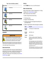
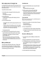
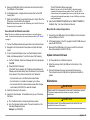
DOC026.97.80271
HHPC 6+, HHPC 3+, HHPC 2+
05/2012, Edition 3
99 Washington Street
Melrose, MA 02176
Phone 781-665-1400
Toll Free 1-800-517-8431
Visit us at www.TestEquipmentDepot.com
User Manual
Table of Contents
Specification
Details
Specifications on page 3
General information on page 3
Battery duration
More than 10 hours with typical use model. Minimum
5.5 hours continuous sampling.
User interface and navigation on page 7
Operation on page 9
Maintenance on page 13
Troubleshooting on page 14
Replacement parts and accessories on page 15
Battery charging
3.5 hours
Data storage
10,000 records
Counting efficiency
50% at 0.3 µm; 100% for particles > 0.45 µm (per ISO
21501)
Zero count level
1 count every 5 minutes (per JIS B9921)
Specifications
Concentration limits
10% at 4,000,000 per cubic foot (per ISO21501)
Count modes
Raw counts, N/CF, N/CM, N/L in Cumulative or
Differential mode
Security
Administrator password controlled (optional)
UI Languages
English and Japanese
HHPC 6+: 6 channels; HHPC 3+: 3 channels; HHPC
2+: 2 channels
Alarms
User-selected particle channels and limits
Weight
0.7 kg (1.5 lbs)
Operating environment
10 ºC to 40 ºC (50 ºF to 104 ºF) / < 95% non
condensing. Pollution degree: II or better.
Flow rate
2.83 lpm. Get ISO 14644-1 class 5 compliant 0.3 um
samples in a minute.
Storage environment
-10 ºC to 50 ºC (14 ºF to 122 ºF) / Up to 98% noncondensing
USB support
Simple data export to memory stick or direct connect to
PC via USB cable. No software required.
Power requirements
(internal)
Internal: Rechargeable Li-Ion 7.4V 2600 mAh battery,
not user-serviceable
Ethernet support
Access particle data over network with an internet
browser such as Windows Explorer, Safari and Firefox
Display
3.5" High resolution 320 x 240 color
Display configuration
User selectable size channels
Display data modes
Traditional tabular particle counts or trend graph
Enclosure
High-impact polycarbonate ABS
Enclosure rating
IP40 Environmental rating. Protected from objects
1 mm in diameter or larger. Not protected from water.
Specification
Details
Size range
0.3 µm - 10 µm channels per ISO 14644-1 (FS 209E)
industry standard; HHPC 2+: 0.5 µm-10µm
Number of channels
Dimensions (L x W x D) 272 x 99 x 54 mm (10.7 x 3.9 x 2.1 in.)
External: External Class III Power Adapter:
100-240 Vac, 50-60 Hz, 1.0A input; 12 Vdc 2.5A output
(Item number 230-300-1000)
Certification
CE
Warranty
1 year
General information
In no event will the manufacturer be liable for direct, indirect, special,
incidental or consequential damages resulting from any defect or
omission in this manual. The manufacturer reserves the right to make
English 3
changes in this manual and the products it describes at any time, without
notice or obligation. Revised editions are found on the manufacturer’s
website.
Safety information
NOTICE
The manufacturer is not responsible for any damages due to misapplication or
misuse of this product including, without limitation, direct, incidental and
consequential damages, and disclaims such damages to the full extent permitted
under applicable law. The user is solely responsible to identify critical application
risks and install appropriate mechanisms to protect processes during a possible
equipment malfunction.
Please read this entire manual before unpacking, setting up or operating
this equipment. Pay attention to all danger and caution statements.
Failure to do so could result in serious injury to the operator or damage
to the equipment.
Make sure that the protection provided by this equipment is not impaired.
Do not use or install this equipment in any manner other than that
specified in this manual.
Use of hazard information
DANGER
Indicates a potentially or imminently hazardous situation which, if not avoided, will
result in death or serious injury.
WARNING
Indicates a potentially or imminently hazardous situation which, if not avoided,
could result in death or serious injury.
CAUTION
Indicates a potentially hazardous situation that may result in minor or moderate
injury.
NOTICE
Indicates a situation which, if not avoided, may cause damage to the instrument.
Information that requires special emphasis.
4 English
Precautionary labels
This is the safety alert symbol. Obey all safety messages that follow
this symbol to avoid potential injury. If on the instrument, refer to the
instruction manual for operation or safety information.
This symbol indicates a laser device is used in the equipment.
Electrical equipment marked with this symbol may not be disposed of
in European public disposal systems after 12 August of 2005. In
conformity with European local and national regulations (EU Directive
2002/98/EC), European electrical equipment users must now return
old or end-of-life equipment to the Producer for disposal at no charge
to the user.
This equipment contains a lithium ion battery. Recycle or dispose of
the battery properly.
Certification
Canadian Radio Interference-Causing Equipment Regulation,
IECS-003, Class A:
Supporting test records reside with the manufacturer.
This Class A digital apparatus meets all requirements of the Canadian
Interference-Causing Equipment Regulations.
Cet appareil numèrique de la classe A respecte toutes les exigences du
Rëglement sur le matériel brouilleur du Canada.
FCC Part 15, Class "A" Limits
Supporting test records reside with the manufacturer. The device
complies with Part 15 of the FCC Rules. Operation is subject to the
following conditions:
1. The equipment may not cause harmful interference.
2. The equipment must accept any interference received, including
interference that may cause undesired operation.
Changes or modifications to this equipment not expressly approved by
the party responsible for compliance could void the user's authority to
operate the equipment. This equipment has been tested and found to
comply with the limits for a Class A digital device, pursuant to Part 15 of
the FCC rules. These limits are designed to provide reasonable
protection against harmful interference when the equipment is operated
in a commercial environment. This equipment generates, uses and can
radiate radio frequency energy and, if not installed and used in
accordance with the instruction manual, may cause harmful interference
to radio communications. Operation of this equipment in a residential
area is likely to cause harmful interference, in which case the user will be
required to correct the interference at their expense. The following
techniques can be used to reduce interference problems:
1. Disconnect the equipment from its power source to verify that it is or
is not the source of the interference.
2. If the equipment is connected to the same outlet as the device
experiencing interference, connect the equipment to a different
outlet.
3. Move the equipment away from the device receiving the interference.
4. Reposition the receiving antenna for the device receiving the
interference.
5. Try combinations of the above.
• Manufacturing processes
• Pharmaceutical production
Three models of the instrument are available. The main differences are
given in Table 1.
The cradle keeps the instrument in an upright position while the
instrument is in use or in storage and while the battery charges. The
cradle also has data and power connections. Refer to Figure 2
on page 6.
Table 1 HHPC models
Cradle accessory
Sensitivity
Number of channels
HHPC 6+
HHPC 3+
HHPC 2+
Standard
Optional
Optional
0.3 µm
0.3 µm
0.5 µm
6
3
2
Product components
Make sure that all components have been received. Refer to Figure 1. If
any items are missing or damaged, contact the manufacturer or a sales
representative immediately.
Class 1 laser product
This instrument is classified as a Class 1 laser product. This product
complies with IEC/EN 60825-1:2007 and 21 CFR 1040.10 except for
deviations pursuant to Laser Notice No. 50, dated June 24, 2007.
US FDA Laser Accession number 9922627-004. This product contains a
non user-serviceable 760-850nm 50 mW class 3B laser.
Product overview
Note: The instrument is designed for indoor use only. Do not place the instrument
in direct sunlight.
The handheld particle counter is a portable instrument that is used to
monitor the air quality in:
• Clean rooms
English 5
For more information on how to use the data and power connections,
refer to Memory and data export on page 12 and Charge the battery
on page 14.
Figure 1 System components
Figure 2 Data and power connections
1 Zero-count filter
5 Handheld instrument
2 Filter adapter
6 USB cable
3 Sample inlet protective cap
7 Cradle accessory (optional)
4 AC adapter
Data and power connections
Figure 2 shows the locations of the data and power connections. The
ethernet port is available only on the cradle.
6 English
1 AC adapter connector
6 Cradle to handheld connector
2 Mini-USB port (from PC)
7 AC adapter connector
3 Cradle to handheld connector
8 USB port
4 USB port (Flash drive or memory
device)
9 Ethernet port
5 Threaded tripod mount
User interface and navigation
User interface
The LCD display screen and the 7-button keypad on the front of the
instrument operate as the user interface (Figure 3). Use the arrow
buttons to navigate in the menu and sub-menu screens and scroll up or
down. Use the Select button to go to the highlighted menu and accept
data.
information on a help screen, highlight the ? icon in the lower-right
corner of the display, then push the Select button. To exit the help
screen, push the Select button again.
Default screen
When the instrument power is applied, the display shows a splash
screen, then the default Sample Screen (Figure 4).
Figure 4 Sample screen
Figure 3 Keypad and display
1 LCD display screen
5 RIGHT arrow button
2 Menu button
6 DOWN arrow button
3 UP arrow button
7 Select button (also Start/Stop
sample)
4 Power button
8 LEFT arrow button
A sample process can be started from this screen. The process uses the
stored Sample Setup values. For more information on how to set up
samples and a sample process, refer to Sample setup on page 10 and
Start a sample process with normal view on page 11.
Help screens
Help screens are available for some menus. Information on the help
screens helps the user set up and use the instrument. To show the
English 7
Menu icons
Icon functions
Icons in the Navigation Menu are shown horizontally. The icon in the
middle of the screen is shown highlighted, (i.e., larger and brighter).
Arrows above and below an icon indicate that sub-menus exist
(Figure 5).
Table 2 shows instrument icons grouped by function. Refer to specific
sections of the manual for more information.
Table 2 Icons and functions
System functions
Figure 5 Example of an icon with submenu options
Instrument diagnostics
Communications setup
System setup
Sign on
Common functions
To go to the Navigation Menu and select a menu option:
1. Push the Menu button.
2. Push the right or left arrow buttons to highlight an icon. Push the Up
or Down arrow buttons to move through sub-menu options.
3. Push the Select button to accept the highlighted icon.
The menu or screen for the selected option appears.
4. View data or edit and configure fields as necessary.
Fields and controls in a screen may include radio buttons, text and
numeric fields, check-boxes and drop down menus. An onscreen
keyboard appears when the cursor is in a text field. Use the
keyboard to put data in the field.
8 English
Trend data view
Sample screen
Buffered data view
Table 2 Icons and functions (continued)
Setup functions
Start up
Push the POWER button to turn on or turn off the instrument.
Location setup
Sample setup
Alarm setup
Display setup
Operation
WARNING
Fire and explosion hazards. Do not use or store the unit in direct
sunlight, near a heat source or in high temperature environments such
as a closed vehicle in direct sunlight. Failure to obey this precaution
can cause the battery to overheat and cause a fire or explosion.
Note: Potential instrument damage. Do not use the instrument in locations with
high static electricity or magnetic fields. Use of the instrument in these areas can
cause invisible damage to instrument safety devices.
About access levels
Basic instrument setup
Make sure that the battery is sufficiently charged before use. To charge
the battery, refer to Charge the battery on page 14.
Refer to the help screen for more information.
To update or change the basic instrument setup:
1. Push the menu button.
2. Navigate to Communication Setup.
3. Push the up or down arrow and navigate to General Setup, then
push the Select button.
4. Update or change the options. Default values appear in parentheses.
Option
Description
Backlight
Timeout
5 -300 seconds (30). 0 disables the feature.
Backlight
Contrast
(High), Medium, Low
Language
English, Japanese
Security
This feature is checkbox controlled. A change to this
setting becomes active when the user exits the General
Setup screen.
If the Security feature is set to on (the box is checked), a
user must select the Sign On icon and put in the current
administrator password to get Administrator level access.
If the feature is on but no password is put in, the user has
only Operator level access.
If the Security feature is set to off (the box is not checked),
a user has both Operator and Administrator level access.
The instrument operates with two access levels, Operator (default) and
Administrator. The access level is controlled by the Security checkbox in
the General Setup menu. For more information about the Security
setting, refer to the help screen in the General Setup menu and to Basic
instrument setup on page 9.
English 9
Option
Description
Change
Password
The default password is 123456. If a user forgets the
password, technical support can supply a temporary
password. The user must give the instrument serial
number and system date for a temporary password to be
generated.
Feedback
Volume
(Intermediate). This setting can be adjusted up or down.
System Date
mm/dd/yyyy, dd/mm/yyyy, yyyy/mm/dd
System Time
12 or 24 hour format
Data display setup
Change the settings for how the instrument shows and stores data in the
Data Display Setup screen.
Different models of the instrument can have different settings and
parameters. Refer to HHPC models on page 5.
To update or change a setting:
1. In the instrument menus, navigate to Sample Setup.
2. Use the up or down arrow keys to navigate to Data Display Setup,
then push the Select button.
The display shows the Data Display Setup screen.
3. Configure the settings. The Data Display Setup screen includes
check-boxes, radio buttons and drop down menu fields. Refer to the
help screen for more information.
The Sample screen changes to agree with the display setup.
Characteristics such as font size may be different for different
configurations.
Verify instrument operation
Electrical noise, sensor leakage or other interference can cause the
instrument to give incorrect data. To make sure the instrument operates
correctly:
1. Attach the Zero-Count Filter.
10 English
2. In the Data Display Setup screen, select the 0.3 µm channel and set
the Concentration mode to COUNTS.
3. In the Sample Setup screen, set the sample time to 5 minutes, the
hold time to 00:00:00, the delay time to 00:00:03, the MODE to
Automatic and the number of CYCLES to 2.
4. Start the Product sampling and let it complete the 2 x 5 minute
samples.
5. Examine the particle counts in the last sample. Counts must align
with these specifications for instrument operation to be verified: No
more than 1 particle > 0.3 µm in 5 minutes.
Purge the instrument
Remove unwanted materials from the instrument before it is used in a
clean-room or clean manufacturing environment. Also do this procedure
after each high sampling count to help keep the internal sensor clean.
1. Install the zero count filter.
2. Set the instrument to sample continuously. Set the Count Mode to
Rate.
3. Start the count process. Continue the count process until there are
no new counts.
4. Remove the zero count filter for normal operation.
Sample setup
Refer to the help screen for more information.
Change the settings for how the instrument runs a sampling process in
the Sample Setup menu. Sub-menus include options for Location,
Alarms and Data display setups. To update or change the Sample Setup
settings:
1. Push the Menu button.
2. Navigate to the Sample Setup icon, then push the Select key.
3. Change the settings for the options. Default values are shown in
parentheses.
Option
Description
Method (Time): The instrument gets a sample for the amount of time in the
Time field.
Volume: The instrument gets a sample equal to the value in the
Volume field.
Time
The instrument gets a sample for the amount of time that is put in
this field. Range: 00:00:01 to 23:59:59 (00:01:00). In the Time
based sampling method, this value plus the hold time equals one
cycle.
Volume The instrument gets a sample equal to the volume put in this field.
In the Volume based sampling method, this value plus the hold
time equals one cycle and the sample time remaining is an
estimated value.
Hold
The amount of time between samples. Range: (00:00:00) to
23:59:59.
Delay
The period of time before the first sample starts after the Start key
is pushed. Range: (00:00:03) to 23:59:59
Cycles
The total number of sample and hold intervals. Range: (0) to 999.
When in Automatic mode, the instrument stops after the last cycle
is complete. A value of 0 makes the unit run continuously until the
user pushes the Select button.
Mode
Automatic: the instrument gets samples according to the stored
parameters.
Start a sample process with normal view
Remove the protective cap from the inlet and attach the correct probe (if
necessary) before starting a sample process.
1. Navigate to the Sample screen icon.
2. Push the Select button to start the sample process.
The instrument begins the sample process with the default or stored
Sample Setup values.
While the instrument takes samples, the display shows the sample
status, current sample number and the sample time that remains
(Sample screen on page 11).
Note: If the Sample Mode is set to Volume, the value for the sample time that
remains is an estimated value based on the Volume in Sample Setup.
3. Let the instrument complete the sample process. To cancel the
sample process, push the Select button again.
The instrument logs data to the data buffer. A status field shows
errors (if any) that occurred in the sample process.
Note: If the sample is manually terminated prior to completion, the data will not
be saved.
Figure 6 Sample screen
Manual: the instrument gets one sample and stops.
Beep: the instrument uses Automatic mode settings but ignores
the count alarm settings. The unit gives an audible beep for each
particle counted.
4. Configure the options for Location, Data display, Communications,
Data export and Alarm Setup as necessary.
English 11
Start a sample process in Trend graph view
View buffered data
In a trend graph, data are plotted in size and count values over time. The
graph updates automatically as new data is available. Historical data can
also be plotted by location.
To plot particle size data in real time:
1. Navigate to the Buffered Data screen icon and push the Select
Button.
The Buffered Data Review screen appears.
2. Push the up or down arrows to scroll through the data.
The data scroll in sequence from the current record.
The data include the date and time of collection, the record number
currently in view, channels and counts, and environmental data
associated with the sample.
1. Push the Menu button and navigate to Trend Data, then push the
Select button.
The trend graph screen appears.
2. Push the Select button.
The Graph Setup screen appears with the Sampling Control icon
active by default.
3. Do one of the tasks that follow:
• Push the Select button to start the sample process with the current
setup OR
• Change the settings in the Graph Setup screen first, then highlight
the Sampling Control icon and push the Select button. Refer to the
help screen for more information about Graph Setup.
The sample process starts.
4. The right hand side of the trend graph is fixed at the most recent
sample. Push the left arrow button to adjust the number of sample
points displayed in the trend graph. The maximum number of
samples displayed is 255.
Note: If historical location data is selected for review at the Trend setup
screen, the x-axis will only be linear if the sample times of each of the data
records are the same. The UP and DOWN arrow buttons control the y-Axis in
half decade steps.
Memory and data export
The instrument keeps collected data in flash memory. The data is kept
when the instrument is shut down. Data can be viewed in the display,
moved to a PC or laptop with a USB cable, put on a USB memory stick
or transmitted through an Ethernet connection.
12 English
Clear the data buffer
Note: If the password security option is set to on, an administrator password is
necessary to remove data from the buffer.
1. Navigate to the clock with a red X icon at the bottom of the screen,
then push the Select key.
A confirmation warning appears.
2. Do one of the steps that follow:
a. Push the Select key to cancel the operation and keep the data.
b. Navigate to the check mark, then push the Select key to remove
data from the buffer.
Move data to a USB memory stick
1. Connect the memory stick to the USB port on the bottom of the
instrument.
2. Navigate to the Buffered Data Icon and push the Select button.
3. In the Buffered Data screen, push the Left arrow until the icon that
shows the USB stick and a green arrow is highlighted. Push the
Select button.
The data export starts automatically. The display shows a successful
export message when the export is complete. Do not remove the
memory stick before this message shows. For buffers with a large
amount of data, the export may take a few seconds.
4. Push the Select button to remove the message.
5. Remove the USB stick from the instrument and connect the stick to
the USB port on the computer.
6. In Windows Explorer, navigate to the computer drive for the USB
memory stick.
7. Right click the DATA.tsv file and select Open with > Excel. When the
file is open, move the data to the computer.
Note: Each time data are saved to the USB memory stick, the DATA.tsv file on
the memory stick is overwritten.
Save data with an Ethernet connection
Note: This option is available only when the instrument is used with a charge
cradle. The cradle is an optional item for some instrument models (HHPC models
on page 5).
1. Connect the Ethernet cable and power cable to the instrument base.
2. Navigate to the Communication Setup menu and push the Select
button.
3. In the Communication Setup screen, set the IP address, Subnet
Mask, and Gateway address. To do this, do one of the following:
a. Put the IP Address, Subnet and Gateway data in the appropriate
fields OR
b. Select the DHCP check box.
If the DHCP box is selected, the IP Address, Subnet Mask and
Gateway are set automatically when the instrument is connected
to the network. The instrument will ask for an IP address if:
• the instrument is put in an Ethernet connected cradle.
• the instrument is in a cradle and a power cycle is done.
• the user exits from the communications screen after changes
were made but the DHCP box was still checked.
4. Install the instrument in the cradle.
5. Open the Internet browser. In the Address bar, put one of the items
that follow:
a. The IP address from the Communication Setup screen
b. hpc+ the instrument serial number. The serial number is in the
instrument Diagnostic screen.
Example: hpc123456789
The HPC Data Web Server page opens.
Note: For this option, the PC and the HHPC+ instrument must be
connected to the same local area network. The PC and the HHPC+
instrument must not be separated by a router, and the network must be
configured to allow packet broadcasting. In case of difficulty, contact your
network administrator.
6. Open the DATAMMDDYYHHMMSS.tsv file. MMDDYYHHMMSS =
the Month, Day, Year, Hour, Minute and Second.
Move data to a mass storage device
1. Connect the mini-USB cable to the mini-USB port on the instrument
and the USB port on the PC.
2. In Windows Explorer on the PC, navigate to the HPC USB drive and
open the DATA.TSV file.
3. Disconnect the USB cable or do a power cycle of the instrument.
New data is added to the DATA.TSV file.
Update instrument firmware
1. Put the update file on a USB memory stick.
2. Attach the memory stick to the USB port on the bottom of the
instrument.
3. Push and hold down the menu key and push the power key.
The instrument scans the USB drive for updates and installs the
update.
Maintenance
WARNING
Multiple hazards. Do not disassemble the instrument for maintenance or service.
If the internal components must be cleaned or repaired, contact the
manufacturer.
CAUTION
Personal injury hazard. Only qualified personnel should conduct the tasks
described in this section of the manual.
English 13
Charge the battery
Clean the instrument
The instrument operates on DC power that is supplied by an internal
rechargeable battery or AC wall adapter. The battery is not user
replaceable. If a new battery is necessary, contact the manufacturer.
A battery icon in the instrument display shows the level of battery power.
The icon flashes when the battery power is at 25% or less and while the
battery charges.
To charge the instrument battery:
Note: Do not use solvents to clean the instrument.
1. Connect the AC wall adapter to a power receptacle.
2. Do one of the tasks that follow:
• Connect the AC adapter plug to the AC adapter connector of the
optional cradle, then attach the instrument to the cradle.
• Connect the AC adapter plug to the AC adapter connector on the
bottom of the instrument.
An amber light on the front of the instrument cradle shows that the
cradle has power. The light turns green when the instrument is
correctly connected to the cradle.
If the AC adapter cord is connected to the instrument, a green light
appears above the AC adapter connector of the instrument.
If the instrument has power, the battery icon in the display flashes
while the battery charges. The icon becomes solid (does not flash)
when the battery is completely charged. A discharged battery
becomes completely charged in about 3.5 hours.
Replace the battery
WARNING
Multiple hazards. Do not disassemble the instrument for maintenance or service.
If the internal components must be cleaned or repaired, contact the
manufacturer.
The battery cannot be replaced by the user. Contact the manufacturer
for battery replacement.
14 English
The instrument is maintenance free. Regular cleaning is not necessary
for normal operation. If the exterior of the instrument becomes dirty, wipe
the instrument surfaces with a clean, moist cloth.
Troubleshooting
Diagnostics screen
The Diagnostics icon is in the Communications Setup sub-menus.
The Diagnostics screen shows information that may be useful in the
analysis of instrument failures.
Information shown includes details about instrument calibration, laser
current, firmware version, battery voltage and battery charge status.
Error descriptions
Table 3 describes the kinds of errors that can occur.
Table 3 Errors
Error type
Description
Stop
A stop error causes all operation to stop until the error is
corrected. The current sample is aborted.
Flow
A flow error causes the counter to stop sampling, and an
error message shows in the display.
Hardware failure Hardware failures are indicated by an error message in the
display. Record any fault codes that show.
Warnings
A warning occurs when a subsystem does not function correctly. When a
warning occurs, the instrument continues to operate and a warning level
indicator shows in the display. When the warning condition is cleared,
the indicator goes out of view.
Table 4 describes the kinds of warnings that can occur.
Table 4 Warnings
Warning
Description
Laser current
Occurs when the laser current exceeds ±30% of the nominal
level.
Buffer full
The instrument is powered on and the buffer is full. Old data
will be overwritten.
Flow system
A Flow Alarm warning occurs when the firmware is unable to
maintain a steady state.
Overconcentration Occurs when concentration limits of the sensor are
detected. The warning clears when concentration values
return to normal.
Calibration failure
Occurs when the calibration signal registers a sensitivity
change of ± 10% size error in the first channel.
Replacement parts and accessories
Note: Product and Article numbers may vary for some selling regions. Contact the
appropriate distributor or refer to the company website for contact information.
Description
Item no.
Adapter for zero count filter
2089398
Charge cradle (HHPC 6+ only)
2089380-01
Power supply
230-300-1000
USB cable
460-400-0002
Zero count filter
VP212808
Test Equipment Depot - 800.517.8431 - 99 Washington Street Melrose, MA 02176
TestEquipmentDepot.com
English 15