1
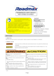
User manual
750 LPH
2015
These machines are designed for intensive use.
They incorporate an automatic cooling system (pre-set) that lights up when the
main tank reaches 35-40°C, the cooling will continue in function even when the
machine is turned off to continue cooling the main tank to restore approximately
35-40°C.
The maximum temperature that the main tank reaches even with intensive work
will be approximately 75 - 78°C.
2
INDEX
FLAME RETAINER............................................................................................. 4
750 LPH MODEL SCHEME................................................................................ 5
MACHINE PREPARATION ................................................................................. 6
WE SEND THE MACHINE WITH THE MIXTURE ALREADY FILLED IN THE
MAIN DEPOSIT, FOR WHICH IS ONLY NECESSARY TO FILL IT WITH
OSMOSIS OR DISTILLED WATER. ................................................................... 6
PREPARATION AND USE.................................................................................. 6
BEFORE TURNING ON THE MACHINE ........................................................ 6
BUBBLER LEVELS .......................................................................................... 12
FLAME RETAINER USE .................................................................................. 13
FLAME RETAINER CLEANING .................................................................... 13
REPEAT OR EXPAND THE CLEANING IN THE SAME ENGINE. ............... 14
DECARBONIZATION PROCEDURE ............................................................... 15
ADVANCED FUNCTIONS CONTROL ............................................................. 17
TURN ON THE MACHINE WITH THE REMOTE CONTROL ....................... 17
HOW TO USE THE RESOURCE REMOTE ................................................. 17
DECARBONISATION CYCLES INFORMATION .............................................. 19
EXITING WITHOUT ERASING THE INFORMATION ................................... 19
TOTAL RUNNING TIME INFORMATION ...................................................... 19
EQUIPMENT TECHNICAL FILE....................................................................... 23
EQUIPAMENT .................................................................................................. 24
EFFICIENCY .................................................................................................... 25
Technical specifications of the display .............................................................. 26
3
FLAME RETAINER
It is only necessary to place the flame retainer when the decarburization is
made on gas or LPG engines.
The warmer the machine becomes, the more likely it is that the flame retainer
become obstructed and expelling less gas, whereby the output pressure gauge
will indicate whether if it is necessary or not clean the flame retainer.
Below we explain how to clean it when necessary.
VERY IMPORTANT
* NEVER APPROACH FLAME SOURCES CLOSE TO FILLING CAPS, OR
GAS OUTPUT TUBE, NOT EVEN WITH THE MACHINE OFF AND WITHOUT
BEING USED FOR DAYS BECAUSE THE GAS KEEPS ACTIVE DURING
MONTHS
THE DEFLAGRATION CAN BE EXTREMELY LARGE, CAUSING SEVERE
DAMAGE TO THE MACHINE.
4
750 LPH MODEL SCHEME
CONTROL PANEL
THERMOMETER
DEPOSIT LED
BUBBLER LED
DEPOSIT MANOMETER
DISTILLED WATER TANK
WATER TANK
SWITCHER
TIMER
GAS OUTPUT
EMERGENCY
MANOMETER
STOP
POTENTIOMETER
5
MACHINE PREPARATION
WE SEND THE MACHINE WITH THE MIXTURE ALREADY FILLED IN THE
MAIN DEPOSIT, FOR WHICH IS ONLY NECESSARY TO FILL IT WITH
OSMOSIS OR DISTILLED WATER.
PREPARATION AND USE
BEFORE TURNING ON THE MACHINE
1) PLUG THE REMOTE START DEVICE
Connect the Jack connector on the machine (back side) and place the device
on top of the engine housing.
It is essential that the place where the device is placed doesn’t raise too much
the temperature. This device detects engine operation by vibration, by which
turn on and off the machine according if the engine is on or off.
2) PLACE THE TUBE IN THE VEHICLE ADMISSION
Before starting the engine and the machine, it’s necessary to place the
tube which is injecting oxyhydrogen gas in the engine intake.
6
HIDROGENOCEL
OFFICIAL REPRESENTATIVE OF ECONOVEDADES GROUP
VERY IMPORTANT:
- All the engine which is going to carry out the treatment should be hot at a
temperature of normal use before starting treatment (80-90º);
- Once open the engine compartment, seek first the air filter. We will seek its
place and follow visually how the air reaches the engine;
- The goal is to introduce the orto-oxyhydrogen gas as close as possible to
the combustion chamber so that there is no gas loss;
- In tourisms and vans always put after the flowmeter;
- As a last resource, given the difficulty of access or overwork to dismantle the
tube that comes to admission, introduce the orto-oxyhydrogen directly by air
filter trying to enter the tube as far as possible (by calculating the distance) to
about 10 centimeters, close to the turbo or the combustion chamber.
ATTENTION:
Fix the tube with a clamp or adhesive tape, so that it is not aspirated in
the case of turbochargers with powerful suction.
3) TURN ON THE SWITCH
SWITCH
7
Wait 10-15s until the LED’s turn on
The first time that the machine is turned on, the LED’s will be red.
4) REGULATE THE POTENTIOMETER
Follow the indications of the sticker on the right.
POTENTIOMETER
STICKER
5) REGULATE THE TIMER
The timer comes pre-set in a 60 minutes cycle.
TIMER
8
HOW TO REGULATE THE TIMER
1) Click once SET and will appear T1;
2) Click again SET and the time will show;
3) Click +
or - (to raise or lower the minutes) - (Possible to
adjust until 99 minutes);
4) Click again SET and will appear T.1;
9
5) Click FNC and the set time will appear;
6) TURN ON THE ENGINE
The machine incorporates a vibration sensor that only allows the machine to
start when it detects the vibrations produced by the engine running. If the
engine stops accidentally, the machine will stop as the timer. The machine will
resume the work when the engine starts running again.
THIS SAFETY IS OF MAXIMUM IMPORTANCE
7) POWER
Control the power in which the machine will run
Once the machine is working, it is necessary to control the power by the values
indicated in the adhesive using the potentiometer.
Don’t pass the recommended Watts.
10
Watt
Power
Amperes
Power factor
Where the amps are indicated its possible that appears the symbol (HHH), this
indicates that the amps value that the monitor can show is passed this is not
important.
What matters to us its the power, the Watts
- Regulate between 1200 and 1400 watts for motors above 1500cc
- Regulate between 1750 and 1850 watts for motors above 7000cc
Watts fluctuations (-100 + 100) are normal and are due to changes in volts of
the electrical network (200 A 230 VOLT)
8) MANOMETERS CONTROL
At the beginning of each cleaning control the gauges. If anyone of them
exceeds the red line, turn off the machine.
* Pressure Gauge deposit (if exceeds the line) means that the valve that is
between the tank and the bubbler is blocked, in this case would be necessary to
contact technical service.
* Gas outlet gauge (overcomes the line) means that the retainer is blocked.
11
BUBBLER LEVELS
The bubbler must be filled with water from the pipe.
To easily fill the bubbler you must take the rubber from the gas outlet so that the
air can go out and facilitate the water entry.
Fill the bubbler until the corresponding LED pass from red to green. If there is
na excess of water the LED will turn on blue.
IMPORTANT:
- When the LED from the bubbler turns on blue you should turn off the machine
and completely empty the bubbler;
- Once empty, turn on again the machine and fill again the bubbler with water
from the pipe until the LED turns GREEN.
- IF THE LED ITS RED OR BLUE THE MACHINE WILL NOT START THE
CLEANIG CYCLE;
- THE TAP TO EMPTY THE BUBBLER IS LOCATED ON THE LATERAL PART
OF THE MACHINE.
ATTENTION:
- Take care to not throw liquids in the electronic panels to not make damage any
electrical component;
- COLSE FIRMLY THE PLUG because if it isn’t close correctly, the gas will
evaporate easily;
- IN THE MAIN DEPOSIT USE ONLY OSMOSIS OU DISTILL WATER.
12
FLAME RETAINER USE
The use of the flame retainer its mandatory when you clean GAS or LPG.
It is not necessary to put it to use the machine for cleaning in diesel engines.
We also recommend not to put it in the cleaning of diesel engines, (because it is
not necessary) that way we have to control it and clean it less often.
CONTROL THE EXIT MANOMETER AT THE BEGGINING OF EACH
CLEANING CYCLE
WHEN THE FLAME RETAINER IS USED YOU SHOULD CONTROL THE EXIT
MANOMETER REGULARLY (EACH 20-30 MINUTES). IF THE MANOMETER
GOES HIGHER THAN THE RED LINE ITS NECESSARY TO DISMANTLE AND
CLEAN IT.
FLAME RETAINER CLEANING
IT IS NECESSARY TO BLOW COMPRESSED AIR DURING 7 SECONDS
WHERE THE COB IS (tube part that goes to the admission - this pipe is
delivered with the machine and is fixed to the retainer flame with a clip).
13
CLEANING CYCLE END
REPEAT OR EXPAND THE CLEANING IN THE SAME ENGINE.
If you want to repeat the cleaning in the same car, proceed this way:
1) Turn off the engine;
2) Delete the main switch of the machine;
3) Turn the main switch on and wait for the LEDs to become green and blinking;
4) Set the time on the timer or leave it as it is;
5) Start the engine.
14
DECARBONIZATION PROCEDURE
THE ENGINE MUST BE HOT, USUAL TEMPERATURE OF WORK (80º - 90º)
We will let the vehicle running so that the orto-oxyhydrogen gas do its main
function which is the incineration of all waste from the combustion chamber, we
should note in a short period of time that the engine sound starts to change
(due to cleaning valves and other moving engine parts).
Every 15-20 minutes is recommend to gradually accelerate the engine to 2500
rpm ace (keep these RPM for about 15-20 seconds) and then take the top for
25-40 seconds.
This action aims at expulsion of burnt particles accumulated during the process
in the exhaust.
During the treatment you may notice an increase in smoke emission, mainly
gray, corresponding to the incineration of waste accumulated.
The treatment will have a variable duration depending on the engine capacity
and the amount of accumulated carbon.
REFERENCE TABLE
Tourisms and vans
60 Minutes
Tractors and industrial
60-70 Minutes
vehicles
Trucks
90 Minutes
15
Once the cleaning ends is recommended to go for a ride with the vehicle about
15 minutes in a forced march, to help expelling the accumulated waste in FAP.
The vehicle will continue expelling residues at least for the next 24 hours.
16
ADVANCED FUNCTIONS CONTROL
TURN ON THE MACHINE WITH THE REMOTE CONTROL
THE MACHINE INCORPORATES A COMMAND THAT ALLOWS ITS WORK IN
A MANUAL WAY, (RESOURCE PROCEDURE) IN CASE THAT FOR ANY
REASON THERE IS NOT A WAY TO TURN ON WITH THE SENSOR (broken
or lost sensor).
ATTENTION:
-IN CASE OF USE OF THE RESOURCE REMOTE CONTROL ALWAYS
START FIRST THE ENGINE BEFORE THE MACHINE AND WHEN THE
CLEANING CYCLE END, ALWAYS TURN OFF AND TAKE THE TUBE FROM
THE ADMISSION BEFORE TURN OFF THE ENGINE.
HOW TO USE THE RESOURCE REMOTE
1) CONNECT BEFORE THE JACK FROM THE REMOTE TO THE MACHINE.
2) Turn on the machine and wait until the LED’s are green in color and blink.
3) When the LED’s are blink, click both buttons (RED AND BLACK) until you
hear a "BIP".
17
10 seconds later, the machine will begin the scheduled cleaning cycle.
If you want to pause the decarburization, it is enough to click the black or red
You can restart by pulsing any button, it will be heard one "BIP" and the cycle
will continue where it was paused.
* After completed the cycle there will only be one way of the machine to restart
a new cycle which will be turning the machine off (switch position 0 in)
18
DECARBONISATION CYCLES INFORMATION
Pressing the black button, you will hear one "BIP" and the LED that indicates
the deposit state will turn blue.
Each time you hear a "BIP" sound, the bubbler LED inform the cycles of
cleanings performed as follows:
LED It refers to the hundred digits
LED It refers to the ten digits
LED It refers to the unity digits
.
It can contain a maximum of 999 Cycles.
EXITING WITHOUT ERASING THE INFORMATION
Pressing the black button will be heard one "BIP" and the bubbler LED
will flash green at a rate of about 2 times/sec.
Turn off the machine (switch in position 0).
TOTAL RUNNING TIME INFORMATION
Pressing the black button, you will hear one "BIP" and the LED that indicates
the deposit state will turn green.
Each time you hear a "BIP" sound, the bubbler LED inform the cycles of
cleanings performed as follows:
LED It refers to the hundred digits
LED It refers to the ten digits
19
LED It refers to the unity digits
.
It can contain a maximum of 999 Cycles.
ATTENTION
This process will erase the information counter
The process is the same for the two modes of information (time and cycles)
When you find information on the time zone or cycles:
Always keep pressed the red button (you will hear-one "BIP")
The bubbler LED will consecutively display three colors (red-green-blue) if we
press at this point the black button, It will confirm the delete process by passing
the LED to fixed red.
If for some reason you decide to not complete the delete process, simply
release the red button before beating the black and will not run the delete
command, (the LED will change to green intermittently).
Once the process is done, turn off the machine (switch position 0).
20
USE RECOMMENDATIONS
* DON’T LEAVE THE MACHINE EXPOSED TO THE SUN OR RAIN
* DON’T SPLIT WATER IN THE BOX OF ELECTRIC POWER.
* DON’T SPLIT WATER IN THE ELECTRONIC PARTES
* CONTROL REGULARLY THE MANOMETERS
* NEVER APPROACH FLAME SOURCES CLOSE TO
FILLING CAPS, OR GAS OUTPUT TUBE OR EVEN WITH
THE MACHINE OFF AND WITHOUT USING FOR DAYS.
GAS CONTINUES ACTIVE FOR MONTHS.
The outbreak CAN BE EXTREMELY STRONG, SERIOUSLY
AND DAMAGING TO THE MACHINE.
* DO NOT OPEN THE MACHINE WITHOUT THE
MANUFACTURER'S CONSENT
21
MAINTENANCE
* FILL THE WATER TANK WHEN IS NECESSARY.
* FILL OR EMPTY THE BUBBLER TANK WHEN IS NECESSARY.
* EMPTY THE MAIN WATER TANK ABOUT EVERY 1500 HOURS OF USE OR
ONCE EVERY 24 MONTHS.
RINSE PROCESS:
ENTER A HOSE WITH WATER (FROM THE PIPE) and totally rinse 1/2 TIMES
THE TANK.
WHEN THE RINSE IS DONE, CALIBRATE AGAIN WITH KHO AND DISTILLED
OR OSMOSIS WATER.
22
EQUIPMENT TECHNICAL FILE
• MODEL 750 LPH CAN CLEAN ENGINES TO 7000 CC
• The HHO gas producer works with 210-250 volts
• Hydrogen Production by Alternating Dry Cell (dry cell)
• Adjustable gas production
• Development and manufacturing in Stainless Steel
• Complies with EC rules
Our machines incorporate safety valves made by measure in Inox
316 L.
Our sources are designed for intensive use and auto regulate
themselves to constantly maintain the required set power, even
though the voltage swing on the order of approximately 15%.
23
EQUIPAMENT
* Adjustable timer from 0 to 99 minutes;
* Temperature sensor with automatic ventilation activation and stop;
* Anti-return valve (stainless steel 316 - Viton) between deposit and bubbler;
* Flame-retainer safety built by measure by Witt
* Relief valve set to the correct working-pressure of 3.5 psi maximum;
* Pressure control gauges in the tank and bubbler;
* LED and sensor of levels with auto stop indication for missing or leftover
liquid;
* Emergency stop button;
* Accessible switch;
* Automatic start sensor (maximum security);
* LED Display (watts- amps - voltage - power factor):
* AC power sources with automatic adjustable frequency with automatic delete
system by overheating or a dead-short;
* Equipped with wheels to transport;
* Emergency initiation device;
* Cycle control and running time device;
* ADJUSTABLE GAS PRODUCTION (CADA 190 WATTS PRODUCES 1 LPM)
24
EFFICIENCY
Cleans the engine parts of petrol, diesel, LPG, ethanol, vegetable oil, methane
vehicle, namely:
•
EGR valve;
•
Pistons;
•
Drum Shirt;
•
Guns;
•
Turbo or not the variable geometry;
•
Catalytic converters;
•
FAP filter
No use of chemicals and without disassembling the engine;
Recovery of power and torque: 10 to 15%;
Restores 10% al 15% of the lost torque;
Restores 8-12% of the lost power;
Restores the yield and initial engine consumption (saving of between 5% to
15% consumption);
Reduces the empty acceleration, noise and engine vibrations;
Increased lifetime of the engine;
Reduces greenhouse gas emissions from the combustion of fuel;
Facilitates and enables the visit of ITV in terms of gas emissions (unburned
hydrocarbons).
25
Technical specifications of the display
Voltage: 180 and 250 Volt
Large amplitude voltage: 200V-250V
Maximum current: 16 A
Display Volt: 0-250
Display (amperes): 0.000A ---- 10
View Watt: 0.0W ---- 2000W
MODEL 750 LPH
Empty weight: 50Kg
Deposit capacity: 30L
530 mm
440 mm
870 mm
26