1
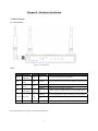
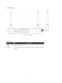
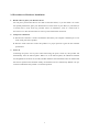
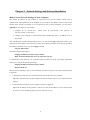
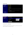
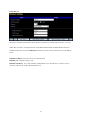
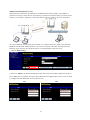
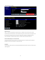
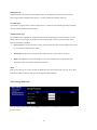
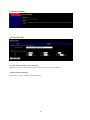
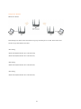
WAP-0010 MIMO Access Point User Manual Ver 1.00-0604 1 Copyright The contents of this publication may not be reproduced in any part or as a whole, stored, transcribed in an information retrieval system, translated into any language, or transmitted in any form or by any means, mechanical, magnetic, electronic, optical, photocopying, manual, or otherwise, without the prior written permission. Trademarks All products, company, brand names are trademarks or registered trademarks of their respective companies. They are used for identification purpose only. Specifications are subject to be changed without prior notice. FCC Interference Statement This equipment has been tested and found to comply with the limits for a Class B digital device pursuant to Part 15 of the FCC Rules. These limits are designed to provide reasonable protection against radio interference in a commercial environment. This equipment can generate, use and radiate radio frequency energy and, if not installed and used in accordance with the instructions in this manual, may cause harmful interference to radio communications. Operation of this equipment in a residential area is likely to cause interference, in which case the user, at his own expense, will be required to take whatever measures are necessary to correct the interference. CE Declaration of Conformity This equipment complies with the requirements relating to electromagnetic compatibility, EN 55022/A1 Class B. 2 Table of Contents CHAPTER 1 INTRODUCTION .......................................................................................................4 FUNCTIONS AND FEATURES ..................................................................................................................4 PACKING LIST.......................................................................................................................................4 CHAPTER 2 HARDWARE INSTALLATION.................................................................................5 2.1 PANEL LAYOUT ...............................................................................................................................5 2.2 PROCEDURE FOR HARDWARE INSTALLATION ..................................................................................7 CHAPTER 3 NETWORK SETTINGS AND SOFTWARE INSTALLATION..............................8 CHAPTER 4 CONFIGURING WIRELESS DEVICE ....................................................................9 4.1 BASIC SETTING .............................................................................................................................10 4.1.1 Primary Setup ......................................................................................................................10 4.1.2 DHCP Server .......................................................................................................................11 4.1.3 Wireless Setup .....................................................................................................................12 WEP (Wired Equivalent Privacy) ............................................................................................................13 802.1X .....................................................................................................................................................14 WPA.........................................................................................................................................................15 WPA-PSK (WPA Pre Shared Key)...........................................................................................................16 WPA2(AES) Advanced Encryption Standard ..........................................................................................17 WPA2-PSK(AES) ....................................................................................................................................18 WPA1/WPA2 ...........................................................................................................................................19 WPA-PSK /WPA2-PSK ...........................................................................................................................20 WDS(Wireless Distribution System) .......................................................................................................21 MAC Address Control .............................................................................................................................22 Advanced Wireless Setting ......................................................................................................................24 4.2.4 Change Password.................................................................................................................25 4.3 ADVANCE SETTING .......................................................................................................................26 4.3.1 System Time ........................................................................................................................26 4.3.2 SNMP Setting ......................................................................................................................27 4.4 TOOLBOX .....................................................................................................................................28 4.4.1View Log ..............................................................................................................................28 4.4.2 Firmware Upgrade ...............................................................................................................29 4.4.3 Backup Setting.....................................................................................................................29 4.4.4 Reset to default ....................................................................................................................30 4.4.5 Reboot..................................................................................................................................30 APPENDIX A TCP/IP CONFIGURATION....................................................................................31 APPENDIX B 802.1X SETTING .....................................................................................................36 APPENDIX C WDS SETTING........................................................................................................41 3 C Chhaapptteerr 11 IInnttrroodduuccttiioonn Congratulations on your purchase of this outstanding Wireless Access Point. This product is specifically designed for Small Office and Home Office needs. It provides a complete SOHO solution for Internet surfing, and is easy to configure and operate even for non-technical users. Instructions for installing and configuring this product can be found in this manual. Before you install and use this product, please read this manual carefully for fully exploiting the functions of this product. Functions and Features Basic functions z z z Auto-sensing Ethernet Switch Equipped with a 4-port auto-sensing Ethernet switch. DHCP server supported All of the networked computers can retrieve TCP/IP settings automatically from this product. Web-based configuring Configurable through any networked computer’s web browser using Netscape or Internet Explorer. Wireless functions z High speed for wireless LAN connection Up to 54Mbps data rate by incorporating Orthogonal Frequency Division Multiplexing (OFDM). z Roaming Provides seamless roaming within the IEEE 802.11b (11M) and IEEE 802.11g (54M) WLAN infrastructure. z IEEE 802.11b compatible (11M) Allowing inter-operation among multiple vendors. z IEEE 802.11g compatible (54M) Allowing inter-operation among multiple vendors. z Auto fallback 54M, 48M, 36M, 24M, 18M, 12M, 6M data rate with auto fallback in 802.11g mode. 11M, 5.5M, 2M, 1M data rate with auto fallback in 802.11b mode. Packing List ■ ■ WAP-0010 MIMO Access Point Power adapter ■ Cat-5 Cable ■ CD Manual 4 C Chhaapptteerr 22 H Haarrddw waarree IInnssttaallllaattiioonn 2.1 Panel Layout 2.1.1. Front Panel Figure 2-1 Front Panel LED: LED Power Status WLAN Link. 1~4 Function Power indication System status Wireless activity Color Status Green On Power is being applied to this product. Green Blinking Status is flashed once per second to indicate system is alive. Green Blinking Blinking The WAN port is sending or receiving data. Sending or receiving data via wireless An active station is connected to the corresponding LAN port. Link status Green On Blinking 10/100M Data Rate Description Green The corresponding LAN port is sending or receiving data. Data is transmitting in 100Mbps on the corresponding LAN port. To reset system settings to factory defaults On Reset Note: Specifications are subject to change without notice. 5 2.1.2. Rear Panel Figure 2-2 Rear Panel LED: Ports: Port Description PWR Power inlet, 12V 1A Port 1-4 the ports where you will connect networked computers and other devices. 6 2.2 Procedure for Hardware Installation 1. Decide where to place your Wireless device You can place your Wireless device on a desk or other flat surface, or you can mount it on a wall. For optimal performance, place your Wireless device in the center of your office (or your home) in a location that is away from any potential source of interference, such as a metal wall or microwave oven. This location must be close to power and network connection. 2. Setup LAN connection a. Wired LAN connection: connects an Ethernet cable from your computer’s Ethernet port to one of the LAN ports of this product. b. Wireless LAN connection: locate this product at a proper position to gain the best transmit performance. 3. Power on Connecting the power cord to power inlet and turning the power switch on, this product will automatically enter the self-test phase. When it is in the self-test phase, the indicators STATUS will be lighted ON for about 10 seconds, and then STATUS will be flashed 3 times to indicate that the self-test operation has finished. Finally, the STATUS will be continuously flashed once per second to indicate that this product is in normal operation. 7 C Chhaapptteerr 33 N waarree IInnssttaallllaattiioonn Neettw woorrkk SSeettttiinnggss aanndd SSooffttw Make Correct Network Settings of Your Computer The default IP address of this product is 192.168.123.254, and the default subnet mask is 255.255.255.0. These addresses can be changed on your need, but the default values are used in this manual. If the TCP/IP environment of your computer has not yet been configured, you can refer to Appendix A to configure it. For example, 1. configure IP as 192.168.123.1, subnet mask as 255.255.255.0 and gateway as 192.168.123.254, or more easier, 2. configure your computers to load TCP/IP setting automatically, that is, via DHCP server of this product. After installing the TCP/IP communication protocol, you can use the ping command to check if your computer has successfully connected to this product. The following example shows the ping procedure for Windows platforms. First, execute the ping command ping 192.168.123.254 If the following messages appear: Pinging 192.168.123.254 with 32 bytes of data: Reply from 192.168.123.254: bytes=32 time=2ms TTL=64 a communication link between your computer and this product has been successfully established. Otherwise, if you get the following messages, Pinging 192.168.123.254 with 32 bytes of data: Request timed out. There must be something wrong in your installation procedure. You have to check the following items in sequence: 1. Is the Ethernet cable correctly connected between this product and your computer? Tip: The LAN LED of this product and the link LED of network card on your computer must be lighted. 2. Is the TCP/IP environment of your computers properly configured? Tip: If the IP address of this product is 192.168.123.254, the IP address of your computer must be 192.168.123.X and default gateway must be 192.168.123.254. 8 C Chhaapptteerr 44 C Coonnffiigguurriinngg W Wiirreelleessss ddeevviiccee This product provides Web based configuration scheme, that is, configuring by your Web browser, such as Netscape Communicator or Internet Explorer. This approach can be adopted in any MS Windows, Macintosh or UNIX based platforms. Start-up and Log in Activate your browser, and disable the proxy or add the IP address of this product into the exceptions. Then, type this product’s IP address in the Location (for Netscape) or Address (for IE) field and press ENTER. For example: http://192.168.123.254. After the connection is established, you will see the web user interface of this product. There are two appearances of web user interface: for general users and for system administrator. To log in as an administrator, enter the system password (the factory setting is ”admin”) in the System Password field and click on the Log in button. If the password is correct, the web appearance will be changed into administrator configure mode. As listed in its main menu, there are several options for system administration. System Menu Once you login the WAP-0010, system menu shows on the right-hand top 9 4.1 Basic Setting In this menu, you can configure IP address, DHCP, Wireless and Change Password 4.1.1 Primary Setup This option is primary to enable this product to work properly. Enter your WAP-0010 IP address here. The default IP address is 192.168.123.254 LAN IP Address: the IP address of this device. The computers on your network must use the LAN IP address of your product. You can change it if necessary. 10 4.1.2 DHCP Server Press “More>>” The settings of a TCP/IP environment include host IP, Subnet Mask, Gateway, and DNS configurations. It is not easy to manually configure all the computers and devices in your network. Fortunately, DHCP Server provides a rather simple approach to handle all these settings. This product supports the function of DHCP server. If you enable this product’s DHCP server and configure your computers as “automatic IP allocation” mode, then when your computer is powered on, it will automatically load the proper TCP/IP settings from this product. The settings of DHCP server include the following items: 1. DHCP Server: Choose “Disable” or “Enable.”, default is “Disable” 2. IP Pool Starting Address/ IP Pool Ending Address: Whenever there is a request, the DHCP server will automatically allocate an unused IP address from the IP address pool to the requesting computer. You must specify the starting and ending address of the IP address pool. 3. Domain Name: Optional, this information will be passed to the client. 4. Primary DNS/Secondary DNS: This feature allows you to assign DNS Servers 5. Primary WINS/Secondary WINS: This feature allows you to assign WINS Servers 6. Gateway: The Gateway Address would be the IP address of an alternate Gateway. This function enables you to assign another gateway to your PC, when DHCP server offers an IP to your PC. 11 4.1.3 Wireless Setup Wireless settings allow you to set the wireless configuration items. Network ID (SSID): Service Set Identifier (SSID). Network ID is used for identifying the Wireless LAN (WLAN). Client stations can roam freely over this product and other devices that have the same Network ID. (The factory setting is “default”). It has a maximum length of 32 characters. SSID Broadcast: The device will Broadcast beacons that have some information, including ssid so that he wireless clients can know how many ap devices by scanning function in the network. Therefore, This function is disabled, the wireless clients can not find the device from beacons. Channel: The 802.11 standard defines a total of 14 frequency channels. The FCC allows channels 1 through 11 within the U.S.; whereas, most of Europe can use channels 1 through 13. In Japan, the channels can be use 1 through 14. Security: Select the data privacy algorithm you want. Enabling the security can protect your data while it is transferred from one station to another. 12 Wireless Security Types WEP (Wired Equivalent Privacy) The privacy service uses a RC4(Ron’s Code 4) based encryption scheme to encapsulate the payload of the 802.11 data frames, called Wired Equivalent Privacy (WEP). WEP is a shared key only. It uses the symmetrical RC4 algorithm and a PRNG (Pseudo-Random Number Generator). The original standard specified 40- (a.k.a. 64) and 128-bit key lengths, with a 24-bit initialization vector (IV). When you enable the 128 or 64 bit WEP key security, please select one WEP key to be used and input 26 or 10 hexadecimal (0, 1, 2…8, 9, A, B…F) digits. 13 802.1X The IEEE 802.1X offers an effective framework for authenticating and controlling user traffic to a protected network, as well as dynamically varying encryption keys. 802.1X ties a protocol called EAP (Extensible Authentication Protocol) to both the wired and wireless LAN media and supports multiple authentication methods, such as token cards, Kerberos, one-time passwords, certificates, and public key authentication. Please refer to Appendix B for more information. Check Box was used to switch the function of the 802.1X. When the 802.1X function is enabled, the Wireless user must authenticate to this device first to use the Network service. RADIUS Server RADIUS IP address or the 802.1X server’s domain-name RADIUS port : Default setting is 1812 RADIUS Shared Key : Key value shared by the RADIUS server and this device. This key value is consistent with the key value in the RADIUS server. Example 14 WPA An effort by the Wi-Fi Alliance to overcome the security limitations of WEP. WPA is subset of the IEEE's 802.11i wireless security specification. Key to WPA is the use of Temporal Key Integrity Protocol (TKIP) to bolster encryption of wireless packets. In addition, WPA will use 802.1x and EAP authentication, based on a central authentication server, such as RADIUS. Check Box was used to switch the function of the WPA. When the WPA function is enabled, the Wireless user must authenticate to this device first to use the Network service. RADIUS Server Encryption TKIP - Temporal Key Integrity Protocol is part of the IEEE 802.11i encryption standard for wireless LANs. TKIP is the next generation of WEP, the Wired Equivalency Protocol, which is used to secure 802.11 wireless LANs. TKIP provides per-packet key mixing, a message integrity check and a re-keying mechanism, thus fixing the flaws of WEP. AES - The Advanced Encryption Standard, also known as Rijndael, is a block cipher adopted as an encryption standard by the US government. It is expected to be used worldwide and analysed extensively, as was the case with its predecessor, the Data Encryption Standard (DES). RADIUS IP address or the 802.1X server’s domain-name RADIUS port : Default setting is 1812 RADIUS Shared Key : Key value shared by the RADIUS server and this device. This key value is consistent with the key value in the RADIUS server. 15 WPA-PSK (WPA Pre Shared Key) One variation of WPA is called WPA Pre Shared Key or WPA-PSK for short. WPA-PSK is a simplified but still powerful form of WPA most suitable for home Wi-Fi networking. To use WPA-PSK, a person sets a static key or "passphrase" as with WEP. But, using TKIP, WPA-PSK automatically changes the keys at a preset time interval, making it much more difficult for hackers to find and exploit them. TKIP - Temporal Key Integrity Protocol is part of the IEEE 802.11i encryption standard for wireless LANs. TKIP is the next generation of WEP, the Wired Equivalency Protocol, which is used to secure 802.11 wireless LANs. TKIP provides per-packet key mixing, a message integrity check and a re-keying mechanism, thus fixing the flaws of WEP. AES - The Advanced Encryption Standard, also known as Rijndael, is a block cipher adopted as an encryption standard by the US government. It is expected to be used worldwide and analysed extensively, as was the case with its predecessor, the Data Encryption Standard (DES). 1. Select Encryption and Pre-share Key Mode If you select HEX, you have to fill in 64 hexadecimal (0, 1, 2…8, 9, A, B…F) digits If it’s ASCII, the length of pre-share key is from 8 to 63. 2. Fill in the key, Ex 12345678 16 WPA2(AES) Advanced Encryption Standard IEEE 802.11i, also known as WPA2, is an amendment to the 802.11 standard specifying security mechanisms for wireless networks. The WPA2 standard supersedes the previous security specification, Wired Equivalent Privacy (WEP), which was shown to have severe security weaknesses. WPA2. 802.11i makes use of the Advanced Encryption Standard (AES) block cipher; WEP and WPA use the RC4 stream cipher. Check Box was used to switch the function of the WPA. When the WPA2 function is enabled, the Wireless user must authenticate to this device first to use the Network service. RADIUS Server RADIUS IP address or the 802.1X server’s domain-name RADIUS port : Default setting is 1812 RADIUS Shared Key : Key value shared by the RADIUS server and this device. This key value is consistent with the key value in the RADIUS server. 17 WPA2-PSK(AES) Similar to the WPA Pre Shared Key but with the Advanced Encryption Standard (AES) block cipher. 1. Select Pre-share Key Mode If you select HEX, you have to fill in 64 hexadecimal (0, 1, 2…8, 9, A, B…F) digits If ASCII, the length of Pre-share key is from 8 to 63. 2. Fill in the key, Ex 12345678 18 WPA1/WPA2 The device will detect automatically which Security type(WPA1 or WPA2) the client uses to encrypt. Check Box was used to switch the function of the WPA1/WPA2 When the WPA1/WPA2 function is enabled, the Wireless user must authenticate to this device first to use the Network service. RADIUS Server RADIUS IP address or the 802.1X server’s domain-name RADIUS port : Default setting is 1812 RADIUS Shared Key : Key value shared by the RADIUS server and this device. This key value is consistent with the key value in the RADIUS server. 19 WPA-PSK /WPA2-PSK The device will detect automatically which Security type(WPA-PSK or WPA2-PSK) the client uses to encrypt. 1. Select Pre-share Key Mode If you select HEX, you have to fill in 64 hexadecimal (0, 1, 2…8, 9, A, B…F) digits If ASCII, the length of Pre-share key is from 8 to 63. 2. Fill in the key, Ex 12345678 20 WDS(Wireless Distribution System) WDS operation as defined by the IEEE802.11 standard has been made available. Using WDS it is possible to wirelessly connect devices, and in doing so extend a wired infrastructure to locations where cabling is not possible or inefficient to implement. Please refer to Appendix C for more information. To create a WDS link the only thing that is needed, is to configure the access points at one end of the WDS link with the MAC address of the PC card in the access point at the other end of the link. The following screen captures show the GUIs that are to be manipulated to make this work. 1. Click the WDS Setting… 2. Select the “Enable” the Wireless Bridging and enter the remote site AP MAC address that needs to have a WDS link. For example: AP1 enter 00:01:6B:40:32:A8 as diagram shown above. Also you need to configure the AP2 WDS MAC as 00:01:6B:40:31:A0 AP1 AP2 21 MAC Address Control MAC Address Control allows you to assign different access right for different users and to assign a specific IP address to a certain MAC address. MAC Address Control Check “Enable” to enable the “MAC Address Control”. All of the settings in this page will take effect only when “Enable” is checked. Connection control Association control Check "Connection control" to enable the controlling of which wired can connect to this device. If a client is denied to connect to this device, it means the client can't access to the Internet either. Choose "allow" or "deny" to allow or deny the clients, whose MAC addresses are not in the "Control table" (please see below), to connect to this device. Check "Association control" to enable the controlling of which wireless client can associate to the wireless LAN. If a client is denied to associate to the wireless LAN, it means the client can't send or receive any data via this device. Choose "allow" or "deny" to allow or deny the clients, whose MAC addresses are not in the "Control table", to associate to the wireless LAN. 22 Control table "Control table" is the table at the bottom of the "MAC Address Control" page. Each row of this table indicates the MAC address and the expected IP address mapping of a client. There are four columns in this table: MAC Address MAC address indicates a specific client. IP Address Expected IP address of the corresponding client. Keep it empty if you don't care its IP address. C When "Connection control" is checked, check "C" will allow the corresponding client to connect to this device. A When "Association control" is checked, check "A" will allow the corresponding client to associate to the wireless LAN. In this page, we provide the following Combobox and button to help you to input the MAC address. You can select a specific client in the “DHCP clients” Combobox, and then click on the “Copy to” button to copy the MAC address of the client you select to the ID selected in the “ID” Combobox. Previous page and Next Page To make this setup page simple and clear, we have divided the “Control table” into several pages. You can use these buttons to navigate to different pages. 23 Advanced Wireless Setting Beacon Interval When a wirelessly networked device sends a beacon, it includes with it a beacon interval, which specifies the period of time before it will send the beacon again. The interval tells receiving devices on the network how long they can wait in low-power mode before waking up to handle the beacon. Network managers can adjust the beacon interval, usually measured in milliseconds (ms) RTS threshold (Request-to-Send Threshold) The RTS threshold specifies the packet size of an RTS transmission. This helps control traffic flow through an access point, especially one with many clients. Fragment In networking, a packet whose size exceeds the bandwidth of the network is broken into smaller pieces called fragments. 24 DTIM interval A DTIM interval, also known as a Data Beacon Rate, is the frequency at which an access point's beacon will include a DTIM. This frequency is usually measured in milliseconds (ms) Preamble Type A preamble is a signal used in wireless environment to synchronize the transmitting timing including Synchronization and Start frame delimiter. Authentication Type The Authentication Type defines configuration options for the sharing of wireless networks to verify identity and access privileges of roaming wireless network cards. You may choose between Open System, Shared Key, and Both. Open System: If the Access Point is using "Open System”, then the wireless adapter will need to be set to the same authentication mode. Shared Key: Shared Key is when both the sender and the recipient share a secret key. Both: Select Both for the network adapter to select the Authentication mode automatically depending on the Access Point Authentication mode. Mode If all of your devices can connect in 802.11g Mode then leave the setting at 802.11g only. If you have some devices that are 802.11b than you can change the mode to Mixed. 4.2.4 Change Password You can change Password here. We strongly recommend you to change the system password for security reason. 25 4.3 Advance Setting 4.3.1 System Time Get Date and Time using PC Date and Time Selected if you want to synchronize the device time setting with your connected PC. Set Date and Time manually Selected if you want to Set Date and Time manually. 26 4.3.2 SNMP Setting In brief, SNMP, the Simple Network Management Protocol, is a protocol designed to give a user the capability to remotely manage a computer network by polling and setting terminal values and monitoring network events. Enable SNMP You must check to enable SNMP function. Get Community Setting the community of GetRequest your device will response. Set Community Setting the community of SetRequest your device will accept. 27 4.4 Toolbox 4.4.1View Log You can View system log by clicking the View Log button Refresh Click the Refresh to update the system log page Download Save the log as text file format Clear logs Clean up the log 28 4.4.2 Firmware Upgrade You can upgrade firmware by clicking Firmware Upgrade button. 4.4.3 Backup Setting You can backup your settings by clicking the Backup Setting button and save it as a bin file. Once you want to restore these settings, please click (1) Firmware Upgrade button, click (2) Browser to select the bin file you’ve saved, then click (3) Upgrade. 29 4.4.4 Reset to default You can also reset this product to factory default by clicking the Reset to default button. 4.4.5 Reboot You can also reboot this product by clicking the Reboot button. 30 A Appppeennddiixx A A T TC CPP//IIPP C Coonnffiigguurraattiioonn This section introduces you how to install TCP/IP protocol into your personal computer. And suppose you have been successfully installed one network card on your personal computer. If not, please refer to your network card manual. Moreover, the Section B.2 tells you how to set TCP/IP values for working with this device correctly. (Windows 98SE as the example) A.1 Install TCP/IP Protocol into Your PC 1. Click Start button and choose Settings, then click Control Panel. 2. Double click Network icon and select Configuration tab in the Network window. 3. Click Add button to add network component into your PC. 4. Double click Protocol to add TCP/IP protocol. 5. Select Microsoft item in the manufactures list. And choose TCP/IP in the Network Protocols. Click OK button to return to Network window. 31 6. The TCP/IP protocol shall be listed in the Network window. Click OK to complete the install procedure and restart your PC to enable the TCP/IP protocol. A.2 Set TCP/IP Protocol for Working with device 1. Click Start button and choose Settings, then click Control Panel. 2. Double click Network icon. Select the TCP/IP line that has been associated to your network card in the Configuration tab of the Network window. 3. Click Properties button to set the TCP/IP protocol for this device. 4. Now, you have two setting methods: 32 a. Select Obtain an IP address automatically in the IP Address tab. b. Don’t input any value in the Gateway tab. 33 c. Choose Disable DNS in the DNS Configuration tab. B. Configure IP manually a. Select Specify an IP address in the IP Address tab. The default IP address of this product is 192.168.123.254. So please use 192.168.123.xxx (xxx is between 1 and 253) for IP Address field and 255.255.255.0 for Subnet Mask field. 34 b. In the Gateway tab, add the IP address of this product (default IP is 192.168.123.254) in the New gateway field and click Add button. c. In the DNS Configuration tab, add the DNS values which are provided by the ISP into DNS Server Search Order field and click Add button. 35 A Appppeennddiixx B B 880022..11xx SSeettttiinngg Figure 1: Testing Environment (Use Windows 2000 Radius Server) 1 Equipment Details PC1: Microsoft Windows XP Professional without Service Pack 1. Wireless Cardbus PC2: Microsoft Windows XP Professional with Service Pack 1a or latter. Wireless Cardbus Authentication Server: Windows 2000 RADIUS server with Service Pack 3 and HotFix Q313664. Note. Windows 2000 RADIUS server only supports PEAP after upgrade to service pack 3 and HotFix Q313664 (You can get more information from http://support.microsoft.com/default.aspx?scid=kb; en-us;313664) 36 2 DUT Configuration: 1.Enable DHCP server. 2.WAN setting: static IP address. 3.LAN IP address: 192.168.123.254/24. 4.Set RADIUS server IP. 5.Set RADIUS server shared key. 6.Configure WEP key and 802.1X setting. The following test will use the inbuilt 802.1X authentication method such as ,EAP_TLS, PEAP_CHAPv2(Windows XP with SP1 only), and PEAP_TLS(Windows XP with SP1 only) using the Smart Card or other Certificate of the Windows XP Professional. 3. DUT and Windows 2000 Radius Server Setup 3-1-1. Setup Windows 2000 RADIUS Server We have to change authentication method to MD5_Challenge or using smart card or other certificate on RADIUS server according to the test condition. 3-1-2. Setup DUT 1.Enable the 802.1X (check the “Enable checkbox“). 2.Enter the RADIUS server IP. 3.Enter the shared key. (The key shared by the RADIUS server and DUT). 4.We will change 802.1X encryption key length to fit the variable test condition. 3-1-3. Setup Network adapter on PC 1.Choose the IEEE802.1X as the authentication method. (Fig 2) Note. Figure 2 is a setting picture of Windows XP without service pack 1. If users upgrade to service pack 1, then they can’t see MD5-Challenge from EAP type list any more, but they will get a new Protected EAP (PEAP) option. 2.Choose MD5-Challenge or Smart Card or other Certificate as the EAP type. 37 3.If choosing use smart card or the certificate as the EAP type, we select to use a certificate on this computer. (Fig 3) 4. We will change EAP type to fit the variable test condition. Figure 2: Enable IEEE 802.1X access control 4. Windows 2000 RADIUS server Authentication testing: 4.1DUT authenticate PC1 using certificate. (PC2 follows the same test procedures.) 1. Download and install the certificate on PC1. (Fig 4) 2. PC1 choose the SSID of DUT as the device. 3. Set authentication type of wireless client and RADIUS server both to EAP_TLS. 4. Disable the wireless connection and enable again. 5. The DUT will send the user's certificate to the RADIUS server, and then 38 send the message of authentication result to PC1. (Fig 5) 6. Windows XP will prompt that the authentication process is success or fail and end the authentication procedure. ( Fig 6) 7. Terminate the test steps when PC1 get dynamic IP and PING remote host successfully. Figure 3: Certificate information on PC1 Figure 4: Authenticating 39 Figure 5: Authentication success 4.2DUT authenticate PC2 using PEAP-TLS. 1. PC2 choose the SSID of DUT as the device. 2. Set authentication type of wireless client and RADIUS server both to PEAP_TLS. 3. Disable the wireless connection and enable again. 4.The DUT will send the user's certificate to the RADIUS server, and then send the message of authentication result to PC2. 5. Windows XP will prompt that the authentication process is success or fail and end the authentication procedure. 6. Terminate the test steps when PC2 get dynamic IP and PING remote host successfully. Support Type: The device supports the types of 802.1x Authentication: PEAP-CHAPv2 and PEAP-TLS. Note. 1.PC1 is on Windows XP platform without Service Pack 1. 2.PC2 is on Windows XP platform with Service Pack 1a. 3.PEAP is supported on Windows XP with Service Pack 1 only. 4.Windows XP with Service Pack 1 allows 802.1x authentication only when data encryption function is enable. 40 A Appppeennddiixx C C W WD DSS SSeettttiinngg How to setup and work: First, check the WLAN MAC address of AP1,AP2 and AP3, please go to command mode and use “Arp -a ”. If you can not find the information of MAC, please make the cable to plug in lan-port of ap and ping the lan ip address then arp -a. There are some information in the screen. For example: AP1 AP2 AP3 IP:192.168.123.254 IP:192.168.123.253 IP:192.168.123.252 Mac:00-11-6b-00-0f-fe Mac:00-11-6b-00-0f-fd Mac:00-11-6b-00-0f-fc SSID: Default SSID: Default SSID: Default Channel: 11 Channel: 11 Channel: 11 DHCP Server: Enable 41 Orange Line: Wireless Black Line: Wired If the Settings are ok,the client1 and client2 can get ip from dhcp server of AP1.Then Client1 and Client2 can get information each other. AP1 Setting: AP1ÅÆ AP2(Remote Mac: 00-11-6b-00-0f-fd) AP1ÅÆ AP3(Remote Mac: 00-11-6b-00-0f-fc) AP2 Setting: AP2ÅÆ AP1(Remote Mac: 00-11-6b-00-0f-fe) AP3 Setting AP3ÅÆ AP1(Remote Mac: 00-11-6b-00-0f-fe) 42