1
0.8m
Dead-zone
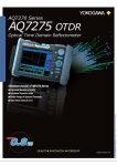
Optical Time Domain Reflectometer
AQ7270 OTDR
Short dead zone (0.8 m)
Wide range of models available supporting
FTTH to metro networks
High performance & easy to use OTDR
Bright & high contrast 8.4 inch LCD screen
www.yokogawa.com/tm
Bulletin AQ7270-01E
8.4 inch
High-intensity
large LCD
Meets a broad range of measurement needs from FTTH to metro networks.
FTTH / FTTB
Metro networks
CO
Access networks
Optical LAN / WAN
Optical power monitor screen
2
3
Use as an Optical Powermeter — Power Monitoring Function
0.8m
Dead-zone
Using the power monitor (factory option), you can check optical power for link loss
testing or when troubleshooting. Useful for checking the optical power at the ONU’s
receiver in FTTH.
40dB
Dynamic range
Light source screen
Use as a Light Source — Light Source Function
The light source (factory option) can be used for optical fiber identification.
Measure Near ...
... or Far ...
— Can detect closely spaced events (up to 0.8m*)
— High dynamic range (up to 40dB)
Accompanying the rapid proliferation of FTTH is a growing
need for detection of reflective events arising from shortdistance mechanical connections. The AQ7270’s event
dead zone is the shortest in the world, enabling detection of
closely spaced events.
The high dynamic range of the AQ7270 enables accurate
measurement of optical fibers in short periods of time. This
makes it a powerful tool for evaluation of metro networks
with relay distances in excess of 100 km, or FTTH (PON)
and other short optical fiber networks with large insertion
loss originating from optical couplers.
*: Based on company research of the field use OTDR, as of November 2006
Choose an Ideal OTDR — 11-Model Lineup
From 1- to 4-wavelength models
The AQ7270 comes in eleven models combining different measurement wavelengths and dynamic ranges.
Supported wavelengths: 1310, 1490, 1550, 1625, 1650 nm (single mode), 850, and 1300 nm (multi mode).
Typical Model
Applicable Number of
Fiber Wavelengths
1
2
SMF
Wavelength
Dynamic Range
Model
1550/1625nm
32dB
34/32dB
40/38dB
38/35dB
735020
735022
735023
735024
1310/1490/1550nm
34/30/32dB
735025
Three-wavelength model for installation and maintenance of PON systems,
supporting 1490 nm
34/32/28dB
735026
Three-wavelength model, supporting a maintenance wavelength of 1625nm
40/38/35dB
735028
High dynamic range three-wavelength model, supporting a maintenance
wavelength of 1625nm
1550nm
1310/1550nm
3
... and Fast
Now measurements can be started quickly upon arrival at the site. 10
seconds to power-up from completely OFF to fully ON! With such a fast
power-up time, battery life can be extended by turning the power off while not
— Powers-up quickly
in use at the job site without any concern about the power-up time when the
(in 10 seconds or less) next job is ready. It’s ready when you’re ready!
1310/1550/1625nm
Descriptions
1550 nm model for access networks and FTTH
For installation and maintenance of access networks and FTTH
For installation and maintenance of metro networks and access networks
Supporting maintenance wavelength 1625nm
MMF
2
850/1300nm
22.5/24dB
735029
Multimode fiber model for LAN maintenance
MMF/SMF
4
850/1300/1310/1550nm
34/32/22.5/24dB
735030
Four-wavelength model for installation and maintenance of LAN and FTTH
with support for both multimode and single mode fiber.
Easy of Operation, Supporting Beginners and Experts
The worldwide spread of broadband services has stimulated the installation of optical fiber in metro and access networks,
which in turn has increased the demand for portable and reliable test equipment to aid the installation and maintenance of
these networks. Our new OTDR has been developed to address these challenges with particular aims of improving operability
to boost work efficiency and cost-effectiveness. The AQ7270 carries forward the basic operation of its predecessors (the
AQ7250 and AQ7260 OTDR), while adding a Detail mode for trained technicians with functions for setting of measurement
conditions and performing manual measurements.
Automated Measurement Function Increases Working Efficiency!
Automatic Setting of Measurement Conditions –Full Auto Mode
Simply choose the measured wavelength, then press a button.
The AQ7270 automatically sets the optimal measurement conditions, performs measurement, performs
event analysis, and saves data. Because you can save to a different file name each time you execute,
measurement and accumulation of data is easy.
Press a button
Select
wavelength
Full Automatic
Setting
λ
Test
Analysis
File save
4
Measurement with Auto Wavelength Switching –Multi Wavelength Measurement Mode
Prepare multiple wavelengths to measure, then press a button.
Multi Wavelength Measurement is a mode in which multiple specified wavelengths from the same
optical port are measured automatically in order. You can also specify to perform analysis or file
saving as needed for each measurement.
Wavelength switches automatically
1625nm
1550nm
λ1
λ2
λ3
1310nm
Macro’s with Predefined Procedures –One Button Mode
Simply choose previously set measurement procedures, then press a button.
You can execute up to five saved measurement procedures in order. A batch of measurement procedures can be run directly from the
main menu. Measurement and analysis conditions can be read from a file, making it easy to set up the measurement procedures.
Measurement Procedures
Execute directly from the main menu
Procedure 1
Procedure 2
Procedure 3
Setting
Setting
Setting
Test
Analysis
File save
Test
Analysis
File save
Test
Analysis
File save
Procedure 1
Procedure 2
Procedure 3
Easy Operation with the Assistance Function!
Measurement Wizard –Assistance setting up measurements
Displays detailed explanations of parameters in the measurement conditions setting
menu, and gives guidelines for setting methods. This function assists unskilled users.
Trained users can enter settings freely in Detail mode.
Measurement Wizard Menu
ACTIVE LINE ALARM –Checking for communication light
Never disturb communication lines
There may be concern that technicians inputting the OTDR measurement signal into the
communication line could cause communication errors. The live line alarm monitors the
fiber’s optical power level and diplays an alarm message if it detects optical power at or
higher than a specified threshold level, in order to warn the technician not to mistakenly
feed the signal into the communication line.
Active Line Alarm Message
PLUG CHECK FUNCTION –Checking the connection with the OTDR
Never spoil measurements with poor connections or dirty plugs
The plug check function monitors the condition of the OTDR’s optical input/output
connectors and displays an alarm if the connection is not properly made. This function is
useful for checking for damage, dirt, or other problems with optical plugs at the OTDR or
on the fiber under test, and for helping technicians to remember to connect the fiber
under test.
5
Plug Check Alarm Message
Detecting Abnormal Events –Fault Event Display Function
The fault event display function detects abnormal connection or reflection points and
displays them. Of the events detected by the event detection function, abnormal events
that cross a specified threshold value are highlighted in the event table and waveform
display.
Fault event
Fault event
Analysis results with Fault Event Display
Fault Event Indication on the waveform
Measurement with Comparison to Reference Waveform –Trace Fix Function
You can freeze the display of one trace and overlap it with real time or averaged
waveforms for comparison. This is useful to create a template when installing multicore
fiber, or for checking aged deterioration during maintenance on existing fiber networks.
In addition to the last-measured waveform, a waveform can be loaded from a file to be
used as the reference waveform.
Reference waveform
Measured waveform
Trace Fix Function
SETUP KEY –Jump to measurement condition setting menu
With the new SETUP button on the front panel, it is easy to move to the measurement
condition setting menu.
Bright 8.4-Inch LCD Screen Easy to Operate with Rotary knob & Arrow Keys
Rotary knob
Front panel
Helps you to easily move the
cursor and change parameters.
Also, you can press the knob
to toggle between fine and
coarse adjustment.
Menu key
Bumper
Soft keys
Protects the unit from
external shocks.
Essential for work in
the field.
Soft keys are used for
menu operation.
Moves to the main menu.
You can select a variety of
measurement functions in
the main menu.
Scale key
Switches between
zooming in/out on the
trace, or
horizontal/vertical shift.
Arrow keys/Enter key
These keys are used to
select and enter items
when setting conditions.
They can also be used
for scaling in the OTDR
trace display.
Setup key
Move to the
measurement condition
settings menu.
Average key
Starts/stops
measurement.
6
Real time key
Hand belt
LCD display
Escape key
File key
For carrying or holding
during one hand
operation.
8.4-inch high intensity
TFT LCD with three
brightness settings.
Escapes from menus.
Opens the file menu.
Side panel
Starts/stops real time
measurement.
Hand belt holder
Shoulder belt holder
Stand
To fix the unit when on a
work bench.
Top panel (Shown with optional Printer/LAN installed)
Printer paper
feed button
Built-in printer
Prints the
measured results
or screen display
Ethernet connector
Used for remote control and
FTP (File Transfer Protocol).
OTDR optical I/O port
Printer/LAN
(Factory option)
Printer paper
lock lever
Battery slot
Slot for mounting the
accessory battery pack.
7
USB (Type B)
DC power connector
Connector for the
accessory AC adapter.
USB (Type A)
OTDR optical I/O port
Light Source/
Power Monitor port
(Factory option)
A port for connecting
external memory or an
external printer.
A port for connecting to an
external PC for remote
control or accessing the
OTDR’s internal memory.
OTDR Screen
Soft key menu
Measured trace
Event table
Overall trace
display
Key Functions
Built-in Dummy Fiber (Factory Option)
Excellent for detecting faults in fiber patch panels!
Fibers in offices frequently involve short distances between connectors. By using the dummy fiber, you can check
whether there is any abnormal near-end connection loss. Also, by measuring the connection loss at the near-end
connector, you can determine the total fiber loss including that of the connector.
Office
Optical fiber cable
Measurement connections in an office
To office-external network
To external
network
Patch panel
Patch panel
Fiber connection point/marker position
Patch cord
Dummy
fiber
Transmitter
Connection loss
Fiber under
test
Built-in dummy fiber
Trace Analysis Functions
8
For Evaluation of Multicore Fiber
For Accurate Splice Loss Measurement by Bi-directional Testing
—Multi Trace Analysis
Up to four traces can be overlaid
on the display for analysis and
comparison.
—2 Way Trace Analysis
Merges the two traces measured
from both directions and finds the
correct splice loss.
This is useful for evaluating
connection point locations and loss
after installing multicore fiber.
Connection loss in lines where optical
fibers of differing backscatter coefficients
are connected can differ depending on
the direction. In such cases, you can
accurately determine the loss by
measuring in both directions and taking
an average.
For Evaluation of Aged Deterioration
For Evaluation of Total Return Loss
—Differential Trace Analysis
Displays the difference between
two specified traces.
—Section Analysis
Finds the total return loss in specific
portions of the fiber.
Makes it simple to check aged
deterioration of fibers or connection
points, or fluctuation in loss between
fibers, and other phenomena.
This type of evaluation is often requested
because the multiple reflections from
optical fiber networks can affect signal
light from transmitters (cable TV etc.).
Smart File Function
Because the AQ7270 makes it easy to differentiate between measured optical fibers—even complex ones—you can add arbitrary
information to file names such as measured wavelength, ID number, tape number, or comments. You can also have the ID number or
tape number automatically updated and saved after each measurement.
Trace data can be saved in SOR and CSV format. Also, you can save screenshots as BMP, JPG, or PNG files. TRB or TRD files saved
on Yokogawa’s previous AQ7250 and AQ7260 models can also be loaded.
File name setting screen
Automatic updating of file names
Concept of the file name structure
Tape fiber
Tape number
ID number
Comment (cable name, etc.)
1310nmYokogawa5a.sor
1310nmYokogawa5b.sor
1310nmYokogawa5c.sor
1310nmYokogawa5d.sor
1310nmYokogawa6a.sor
Tape No. change
Tape No. change
Tape No. change
ID number &
tape No. change
Language Selection
In addition to English (standard), you can select a display language of French, German, Chinese, Korean, Russian, and others.
USB Function
USB connectivity makes it more convenient to output to external memory or printers, and to set up communication. The
AQ7270 comes standard with two USB1.1 compliant connector ports (Type A and Type B).
• Saving Files to USB Memory—Type A
• Printing on an External Printer—Type A
Using USB memory or a USB
hard disk, you can save large
amounts of data. Also, you can
easily transfer saved data to a
PC or other device.
• Remotely Controlling the AQ7270 from a PC—Type B
You can print screen images or
measured data on USB
printers.
• Accessing the AQ7270 Internal Memory from a PC—Type B
The AQ7270 can be remotely
controlled from an external PC
by connecting a USB cable from
one to the other.*
You can easily access to
internal memory with USB
cable from a PC.*
9
*: USB type A - type B cable required for remote control.
Measured Data Analysis and Report Creation Tool
AQ7932 OTDR Emulation Software (Sold Separately)
AQ7932 is application software that performs analysis of trace data
measured by the AQ7270 OTDR on a PC, and creates reports. The report
creation wizard makes this task simple. AQ7270 OTDR data can be easily
loaded onto a PC using USB memory or the communication interface.
Trace
Analysis
You can edit event search conditions, approximate curve line
settings, and other conditions, and then repeat the analysis. And
now it is even easier to operate; simply click the function icon
with the mouse.
Analysis
Functions
Display up to eight traces on screen and perform a variety of
different analyses including: multi trace analysis, differential trace
analysis for comparing recent waveforms with old ones, and 2
way trace analysis function for analyzing average values of data
measured from both directions in the optical fiber.
Creating
Reports
Compiles trace and measured values from trace files and
creates a report. Reports can also be created in Excel or CSV
format. Reports are easy to create by following the step-by-step
instructions in the report wizard.
Note Operating System: Microsoft Windows 2000, XP
Excel: Microsoft Excel 2000, XP, 2003
Specifications
Common Specifications
Horizontal Axis Parameters
Optical I/O port
Sampling resolution
Connector type
5 cm, 10 cm, 20 cm, 50 cm, 1 m, 2 m,
4 m, 8 m, 16 m, 32 m
Readout resolution
1 cm (Min.)
Number of sampled data Up to 50,000 points
Group refractive index
1.30000 to 1.79999 (in 0.00001 steps)
Unit of distance
km, kf, or miles
Distance measurement accuracy
Offset error: ±1 m
Scale error: Measured distance҂2҂10-5
Sampling error: ±1 sampling resolution
Vertical Axis Parameters
Vertical axis scale
0.2 dB/div, 0.5 dB/div, 1 dB/div,
2 dB/div, 5 dB/div, 7.5 dB/div
Readout resolution
0.001 dB (Min.)
Loss measurement accuracy*
±0.05 dB/dB
* When the measuring loss is 1dB or less, the accuracy is within ±0.05dB
OTDR Measurement Function
Distance measurement
10
Loss measurement
Return loss measurement
Displays up to eight digits of the
relative one-way distance between two
arbitrary points on the trace.
Displays one-way loss in steps of
0.001 dB to a maximum of 5 digits.
Displays the one-way loss, loss per
unit length, and splice loss between
any two given points on the waveform.
Measures return loss and total return
loss of a fiber cable or between two
arbitrary points on the trace.
SC (fixed), FC (fixed), SC universal adapter,
FC universal adapter, No universal
adapter (base)
1 or 2*
Number of port
* Port 2 is only for model 735027 (1650nm), and Model 735030 (850nm/1300nm).
File Formats
File formats
Read: SOR, TRD, TRB, SET
Write: SOR (Telcordia), SET, CSV,
BMP, JPG, PNG
General Specifications
Laser safety standards
Safety standard
Emission
Immunity
Operating environment
Temperature
Humidity
Storage temperature
Battery
AC adapter
Rated supply voltage
Rated supply frequency
Power consumption
Dimensions
Weight
OTDR Analysis Functions
Analysis functions
Multi trace analysis, 2 way trace
analysis, differential trace analysis,
section analysis
class 1 M (IEC60825-1:2001)
EN61010-1
EN61326 Class A
EN61326 Annex A
0 to 45°C
(0 to 35°C when charging the battery)
85% RH or less (no condensation)
-20 to 60°C
Operation time 6 hours*1
Recharge time 5 hours*2
100 to 240 VAC
50 to 60 Hz
Max 70 W
(when battery charging, and optional
printer printing)
(W) 287҂(H) 197҂(D) 85 mm
(not including projections or options)
Approx. 2.8 kg
(not including options)
*1 Measurement for 30 seconds in every 10 minutes, without
any options, in power save mode (Full Auto 1minute).
*2 Ambient temperature of 23°C, power OFF
Laser Safety Label
Internal Memory
Memory capacity
1000 waveforms or more
Can store measured waveforms, and
measurement conditions
External Dimensions
Unit: mm
Display
Display
Total number of pixels*
(/PL)
8.4-inch color TFT LCD
640 (horizontal)҂480 (vertical)
* The LCD may contain some pixels that are always ON or always OFF (0.002% or fewer of
all displayed pixels including RGB), and is not indicative of a general malfunction.
Top
USB
USB1.1 Type A and Type B, one each
Type A: For external memory or
external printer
Type B: For connecting to an external
PC for remote control or
access to the OTDR’s internal
memory.
197
External Interface
6
287
Front
6
85
85
Side
135
(/PL)
50
Specifications by Model
Single-mode Fiber 1 Wavelength Type
Model
735020
Wavelength
Applicable fiber
Distance range
Pulse width
*3
*4
Dynamic range
Event dead zone*5, 11
Attenuation dead zone*6, 11
735021
Single-mode Fiber 2 Wavelength Type
*12
1650 ± 5nm *1
1550±25nm
±10nm *2
SM (ITU-T G.652)
500m, 1km, 2km, 5km, 10km, 20km,
50km, 100km, 200km, 300km, 400km
3ns, 10ns, 20ns, 50ns, 100ns, 200ns,
500ns, 1us, 2us, 5us, 10us, 20us
32dB
30dB
0.8m
0.8m
8m (typ)
12m (typ)
Model
735022
Wavelength
Applicable fiber
Distance range
Pulse width
735024
735023
1310/1550±25nm
*3
Dynamic range*4
Event dead zone*5, 11
Attenuation dead zone*6, 11
1310/1550±25nm
1550/1625±25nm
SM (ITU-T G.652)
500m, 1km, 2km, 5km, 10km, 20km, 50km,
100km, 200km, 300km, 400km
3ns, 10ns, 20ns, 50ns, 100ns, 200ns, 500ns,
1us, 2us, 5us, 10us, 20us
34/32dB
40/38dB
38/35dB
0.8m
0.8m
0.8m
7/8m (typ)
7/8m (typ)
8/12m (typ)
Single-mode Fiber 3 Wavelength Type
Model
Wavelength
Applicable fiber
Distance range
Pulse width*3
Dynamic range*4
Event dead zone*5, 11
Attenuation dead zone*6, 11
735025
Model
Distance range
Pulse width
*3, 7
Dynamic range*8, 10
Event dead zone*9, 10, 11
Attenuation dead zone*6, 10, 11
735028
1310/1550±25nm
1310/1490/1550±25nm
1310/1550/1625±25nm
1310/1550/1625±25nm
1650±5nm *1, ±10nm *2
SM (ITU-T G.652)
500m, 1km, 2km, 5km, 10km, 20km, 50km, 100km, 200km, 300km, 400km
3ns, 10ns, 20ns, 50ns, 100ns, 200ns, 500ns, 1us, 2us, 5us, 10us, 20us
34/30/32dB
34/32/28dB
40/38/35dB
34/32/30dB
0.8m
0.8m
0.8m
0.8m
7/8/8m (typ)
7/8/12m (typ)
7/8/12m (typ)
7/8/12m (typ)
Multimode Fiber 2 Wavelength Type
Wavelength
Applicable fiber
735027 *12
735026
735029
Multimode/Single-mode Fiber 4 Wavelength Type
Model
735030
850/1300±30nm
GI (50/125, 62.5/125µm)
500m, 1km, 2km, 5km, 10km,
20km, 50km, 100km
Wavelength
Applicable fiber
10ns, 20ns, 50ns, 100ns,
200ns, 500ns, 1us, 2us, 5us
22.5/24dB
2m (typ)
7/10m (typ)
Pulse width
Distance range
*3
Dynamic range
Event dead zone
Attenuation dead zone
*1 At a point -20 dB from the pulse light output peak value (measured 30 min. or more after power ON,
ambient temperature of 23°C)
*2 At a point -60 dB from the pulse light output peak value (measured 30 min. or more after power ON,
ambient temperature of 23°C)
*3 Pulse width setting range depends on the distance range.
*4 SNR=1, at pulse with 20 µs, distance range 200 km, sampling resolution 32 m, measurement time 3 minutes.
*5 Pulse width 3 ns, return loss 45 dB or more, at a point 1.5 dB below the peak value (not saturated).
1310/1550±25nm
SM (ITU-T G.652)
500m, 1km, 2km, 5km, 10km, 20km,
50km, 100km, 200km, 300km,400km
850/1300nm±30nm
GI (50/125,62.5/125µm)
500m, 1km, 2km, 5km,
10km, 20km, 50km, 100km
3ns, 10ns, 20ns, 50ns, 100ns, 200ns,
500ns, 1us, 2us, 5us, 10us, 20us
34/32dB*4
0.8m*5, 11
7/8m (typ)*11
10ns, 20ns, 50ns, 100ns, 200ns,
500ns, 1us, 2us, 5us*7
22.5/24dB*8, 10
2m (typ)*9, 10, 11
7/10m(typ)*6, 10, 11
*6 Pulse width 10 ns, return loss 45 dB or more, at a point where the backscatter level is within ±0.5 dB of the
normal value.
*7 Pulse width of 2 or 5 µs when measured wavelength is 1300 nm
*8 SNR=1, at pulse width 200 ns(850nm), 1 µs(1300nm), measurement time 3 minutes.
*9 Pulse width 10 ns, return loss 45 dB or more, at a point 1.5 dB below the peak value (not satunated).
*10 GI (62.5/125 µm) is measured.
*11 At group refractive index 1.5
*12 Pulse light output power at 1650 nm less than 15 dBm
Note: Specifications without any special remarks, assured at 23±2°C
Factory Installed Option Specifications
Built-in Printer/LAN Functions (/PL option)
Power Monitoring Function (/PM Option)
Printing method
Dot density
Paper width
Operating environment
Optical port
Measuring range*1
Measurement accuracy*2
Storage temperature
LAN function
Thermal line-dot
576 dots/line
80 mm
Temperature 5 to 35°C
Humidity 10 to 80% RH (no condensation)
-20 to 60°C
10BASE-T/100BASE-TX (RJ-45) x1
OTDR optical I/O port
-50 to -5 dBm
±0.5 dB
*1 CW light, wavelength 1310 nm, absolute max input level = 0 dBm (1 mW)
*2 When inputting CW light, wavelength 1310 nm, -10 dBm, at 23±2°C
Light Source Function (Option /LS)
Dummy Fiber (/DF Option)*
Optical port
Center wavelength
Output level
Output level stability
Modulation frequency
Optical fiber
Length
OTDR optical I/O port
OTDR’s center wavelengths
-5 dBm or more (at 23±2°C)
±1 dB (5 minutes)
CW, 270 Hz
Single-mode fiber (ITU-T G.652)
approx. 100 m
* Dummy fiber option may cause the reduction of dynamic range (0.5dB or less).
11
Accessories (Optional)
Model and Suffix Codes
AQ7270 OTDR
Name
Option availability
Model
/PM
/LS
/PL
/DF
/SB
735020
735021
735022
735023
735024
735025
735026
735027
735028
735029
735030
–
*1
–
*2
–
*2
–
–
Description
AQ7270 OTDR 1550nm, 32dB
AQ7270 OTDR 1650nm, 30dB
AQ7270 OTDR 1310/1550nm, 34/32dB
AQ7270 OTDR 1310/1550nm, 40/38dB
AQ7270 OTDR 1550/1625nm, 38/35dB
AQ7270 OTDR 1310/1490/1550nm,
34/30/32dB
AQ7270 OTDR 1310/1550/1625nm,
34/32/28dB
AQ7270 OTDR 1310/1550/1650nm,
34/32/30dB
AQ7270 OTDR 1310/1550/1625nm,
40/38/35dB
AQ7270 OTDR 850/1300nm,
22.5/24dB
AQ7270 OTDR 850/1300/1310/1550nm,
22.5/24dB/34/32dB
*1 : Does not support the 1650nm port *2 : Does not support the 850/1300nm port
: Available – : Not available
Suffix Codes
Optical
-SCC
Connector -FCC
-NON
-USC
-UFC
Language
-HE
-HC
-HK
-HR
Power
-D
Cord
-F
-R
-Q
-H
Options
/PM
/LS
/PL
/DF
/SB
SC type
FC type
80mmx25m
UL/CSA standard
VDE standard
AS standard
BS standard
GB standard, Complied with CCC
Application software
Model
Suffix Codes
735070
Specifications
AQ7932 OTDR Emulation Software (Ver3.0 or later)
English
-EN
Description
SC type Connector
FC type Connector
No universal adapter
Universal adapter (SC)
Universal adapter (FC)
English
Chinese/English
Korean/English
Russian/English
UL/CSA standard
VDE standard
AS standard
BS standard
GB standard, Complied with CCC
Optical power monitor
Light source
Built-in printer, LAN
Dummy fiber (SMF)
Sholder belt
Specifications
Model
739860
739880
SU2005A-SCC
SU2005A-FCC
A9010ZP
B8070CY
739870-D
739870-F
739870-R
739870-Q
739870-H
Soft carrying case
Battery pack
Universal adapter(SC)
Universal adapter(FC)
Printer roll paper
Shoulder belt
AC adapter
Related Products
OTDR
LD Light Source
AQ7260
AQ4270-01
High performance OTDR that also
supports long-distance optical fiber
cables, with high dynamic range of up to
45 dB.
Compact, lightweight 1310/1550 nm 2wavelength light source with 4 switches for
easy, safe operation.
Optical Powermeter
Optical Powermeter
Example: 735023–USC–HE–D /PM /LS
AQ7270 OTDR 1310/1550nm, 40/38dB, with Universal adapter(SC), English version,
with a UL/CSA standard power cord, with power monitor function and with Light source
function
AQ2160-01
Standard Accessories
An AC adapter, a power cord, a battery pack, a hand belt,
and a set of user’s manual (CD-ROM)
Compact, lightweight powermeter
designed especially for absolute value
measurements for FTTH/LAN work.
AQ2160-02
Compact, light weight body. Using with a
light source, it can measure optical loss.
Measured values can be saved to internal
memory, making on-site work more
efficient.
Microsoft, MS, and Windows are registered trademarks or trademarks of Microsoft
Corporation in the US and other countries.
YOKOGAWA CORPORATION OF AMERICA
2 Dart Road, Newnan, Georgia 30265-1094, U.S.A.
Phone: (1)-770-253-7000, Fax: (1)-770-251-6427
Represented by :
YOKOGAWA EUROPE B.V.
Databankweg 20, 3821 AL, Amersfoort, THE NETHERLANDS
Phone: (31)-33-4641858, Fax: (31)-33-4641859
YOKOGAWA ENGINEERING ASIA PTE. LTD.
5 Bedok South Road, Singapore 469270
Phone: (65)-62419933, Fax: (65)-62412606
YOKOGAWA MEASURING INSTRUMENTS KOREA CORP.
Phone: (82)-2-551-0660, Fax: (82)-2-551-0665
YOKOGAWA SHANGHAI TRADING CO., LTD.
Phone: (86)-21-5405-0303, Fax: (86)-21-6880-9254
YOKOGAWA ELECTRIC CORPORATION
Communication & Measurement Business Headquarters
2-9-32 Nakacho, Musashino-shi, Tokyo, 180-8750 Japan
Phone: (81)-422-52-6768, Fax: (81)-422-52-6624
MM-16E
E-mail: [email protected]
Subject to change without notice.
All Rights Reserved, Copyright© 2006, Yokogawa Electric Corporation.
[Ed : 02/b]
Printed in Japan, 702(KP)