1
Parameters and Register Addresses
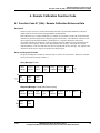
Overview
3. Parameters and Register Addresses
3.1 Overview
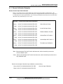
Introduction
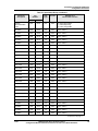
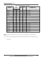
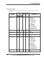
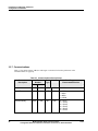
This section provides maps of the configuration parameters in the Herculine actuator. Using Function
codes 20 and 21 you can read and write configuration values to the actuator. The configuration parameters
are arranged according to the set up groups in which they appear when using the local display and keypad
interface.
Each parameter is listed with its register address, data format type (32-bit floating point or 16-bit integer)
and available selections.
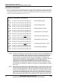
General Information
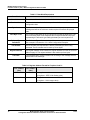
Analog / Digital Parameters
Whenever configuration parameter values are changed via communications, a write cycle occurs after the
response is returned acknowledging receipt of the message.
3.2 Configuration Parameters
Overview
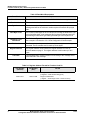
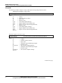
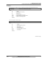
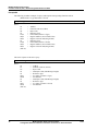
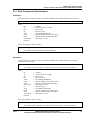
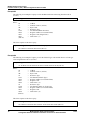
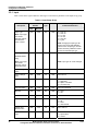
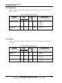
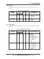
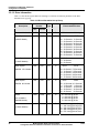
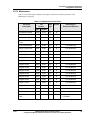
Listed on the following pages are the parameters in the various set-up groups within the actuator. The setup groups and their table numbers are listed below. Most of the parameters are configurable through the
hosts. Some parameters are read only and are indicated as such and therefore cannot be changed.
Set-up Group
See Table Number
Input................................................................................................................ Table 3-1
Relay1 ............................................................................................................. Table 3-2
Relay2 ............................................................................................................. Table 3-3
Relay3 ............................................................................................................. Table 3-4
Relay4 ............................................................................................................. Table 3-5
Current Output ................................................................................................ Table 3-6
Communications ............................................................................................. Table 3-7
Digital Input.................................................................................................... Table 3-8
Display............................................................................................................ Table 3-9
Lockout ........................................................................................................... Table 3-10
Status............................................................................................................... Table 3-11
Drive Information ........................................................................................... Table 3-12
Maintenance.................................................................................................... Table 3-13
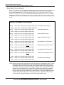
Reading or Writing
Do a read or write, depending on your requirements, using the format code listed in the tables. The range
or selection available for each range is listed in the tables.
11/03
Modbus® RTU Serial Communications
Configuration/Remote Calibration Interfaces for HercuLine Smart Actuators
17