1
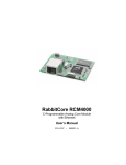
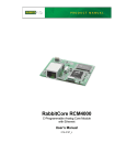
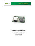
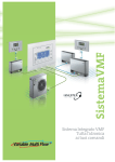
Network Storage Center Setup
1. Install the hard drive in the Network Storage Center as shown at right.
1. Remove a screw from the bottom
of the base stand.
2. Plug in the AC power adapter and use either a straight-through or a crossover Ethernet cable to connect the Network Storage Center to your PC.
2. Separate the base stand and
enclosure, then pull out the disk
mounting tray.
3. If you are using Windows Vista, set the firewall to “Private.”
4. Install the IP Scanner utility from the setup CD that came with the Network
Storage Center.
5. Use the on/off switch to turn the Network Storage Center on, then restart
your PC to obtain a new IP address from the Network Storage Center.
IDE
Connector
Power
Connector
1. Install Dynamic C, then run the executable on the supplemental CD to add the SMB Application Kit software.
2. Attach RCM4010 module to Prototyping Board, connect programming cable to PC, connect AC adapter.
6. Point your Web browser to http: //169.254.0.1/. A login dialog will
appear. The default username and password are both admin.
4. Turn the disk mounting tray around
secure the hard drive with 4 screws.
3. Install the hard drive in the Network Storage Center and configure the Network Storage Center via your PC.
4. Use an Ethernet cable to connect the RCM4010 to the configured Network Storage Center
7. Change the Host Name to thindrive to match the Dynamic C REMOTE_
SERVER macro in the LIB\ThinShare\SMB_CONFIG.LIB library.
8. Click on Samba Server and add SAMPLES to the folder list.
3. Secure the power and IDE cable
to the hard drive.
Quick Start Guide
5. Slide disk mounting tray back into
enclosure, then replace screw at
the bottom of the base stand that
you removed in Step 1.
ON/OFF
AC Power
To
PC or RCM4010
TIP: The Network Storage Center has a DHCP server. Leave the DHCP
server on the Status tab enabled as long as you plan to connect the
RCM4010 directly to the Network Storage Center or via a network
without a DHCP server. You must disable the Network Storage Center’s
DHCP server if your connection to the RCM4010 is via a network with a DHCP server.
6. Connect the server to your PC
or to the RCM4010, and to
AC power.
Where Do I Go From Here?
You are now ready to run the SMB sample programs in the Dynamic C SAMPLES\ThinShare folder. Use either a
straight-through or a crossover Ethernet cable to connect the Network Storage Center to the RCM4010 Ethernet jack.
TIP: The sample programs assume that the Network Storage Center and the RCM4010 will be connected
with a DHCP server present. If you make a direct connection where there is no DHCP server, change the
TCPCONFIG 3 macro in the sample programs to TCPCONFIG 1 before you compile and run the sample
programs. You will have to assign a static IP address (default IP 10.10.60.100, Subnet Mask 255.255.255.0,
and Gateway 10.10.6.1) to the Network Storage Center.
The SMBSHELL.C is a good first sample program to run to display an interactive command-line shell with a large
number of common SMB commands in the Dynamic C STDIO window.
If the sample program ran fine, you are now ready to go on to other sample programs and to develop your own applications. The source code for the sample programs is provided to allow you to modify them for your own use. The
Embeo Getting Started and Samples manual and ThinShare User’s Manual on the supplemental CD contain additional setup information, describe the sample programs, and provide a complete technical reference for the ThinShare
library and function calls. The RCM4000 User's Manual on the Dynamic C CD also provides complete hardware
reference information and describes the software function calls for the RCM4010 RabbitCore modules and the Prototyping Board. The Setup CD has a reference manual for the Network Storage Center.
5. Explore the sample programs in the Dynamic C SAMPLES\ThinShare folder.
SMB Network Storage Application Kit
The SMB Network Storage Application Kit allows you to add an SMB server to a Rabbit-based system
that enables file sharing to add attached storage. Sample programs show you how to create a new file on
the server and write data to it, and provide an interactive command-line shell.
Application Kit Contents
• 2 CD-ROMs — Dynamic C® with complete product documentation on disk, and supplemental CD
with sample programs and information related to the SMB Application Kit.
• Network Storage Center with AC power supply, international adapter plugs, setup CD, and instructions.
• 3.5" IDE hard drive.
• RCM4010 RabbitCore® module.
• Prototyping Board.
• Universal AC adapter, 12 V DC, 1 A (includes Canada/Japan/U.S., Australia/N.Z., U.K., and
European style plugs). Application Kits sold in North America may contain an AC adapter with
only a North American style plug.
• Bag containing accessory parts, screws, washers, and standoffs.
• USB programming cable with 10-pin header.
• Cat. 5 Ethernet crossover cable.
If there are any other problems:
• Use the Dynamic C Help menu to get further assistance with Dynamic C.
• Check the Rabbit Semiconductor Technical Bulletin Board and forums at www.rabbit.com/support/bb/ and at
www.rabbit.com/forums/.
• Use the Technical Support e-mail form at www.rabbit.com/support/.
NOTE: If you purchased your SMB Application Kit through a distributor or through a Rabbit partner, contact
the distributor or partner first for technical support.
020–0137
•
080229–A
• Getting Started instructions.
• Rabbit 4000 Processor Easy Reference poster.
• Registration card.
Visit our online Rabbit store at www.rabbit.com/store/ for
the latest information on peripherals and accessories that
are available for all RCM4000 RabbitCore module models.
Installing Dynamic C®
Insert the Dynamic C CD from the Application Kit in your PC’s CD-ROM drive. If
the installation does not auto-start, run the
setup.exe program in the root directory
of the Dynamic C CD. Run the executable
from the supplemental CD to install the
SMB software after you install Dynamic C.
Rabbit, RabbitCore, Dynamic C, and Digi are registered trademarks of Digi International Inc.
Step 4 — Connect Power
Hardware Connections
Once all the other connections have been made, you can connect power to the Prototyping Board.
Step 1 — Prepare the Prototyping Board
L2
R4
R3
R5
C10
U1
R9
RXD
TXD
GN
D
RX87
CX41
CX39
UX45
AG
ND
CX29
LN5IN AGND
R11
R12
LN3IN
LN7IN
LN1IN
VREF
CVT
LN2IN
LN4IN
R27
R28
AGND
CX17
RX85
JP17
JP13
C9
C11
C13
LN6IN
LN0IN
JP21
JP22
JP20
R15
R17
R7
R5
TXC
RXC
R2
+3.3 C4
V
D2
R26
JP11
JP15
JP19
R14
R13
R18
R16
R3
R6
R8
R4
C7
C10
C8
RX61
UX41
UX42
RX65
UX37
RX63
R22
R24
S3
GND
UX16
GND
1
GND
Plug in the AC adapter. The PWR LED on the Prototyping Board next to the power connector at J1
should light up. The RCM4010 and the Prototyping Board are now ready to be used.
Run a Sample Program
Insert tab into slot
Assemble
AC Adapter
Once the RCM4010 is connected as described in the preceding pages, start Dynamic C by double-clicking
on the Dynamic C icon on your desktop or in your Start menu. Dynamic C uses the serial port specified
during installation. Select the “Communications” tab and verify that Use USB to Serial Converter is
selected to support the USB programming cable. Click OK.
AC Adapter
Snap plug into place
R2
R2
PC2
PC4
PC6
PE0
PE2
PE3
R19
PE5
R9
PE7
PE4
PD1
LN1
PD2
LN2
PD4
LN4
PD6
LN6
RXD TXD
GND
J4
UX29
RX87
CX41
CX39
UX10
RX67
UX12
RX85
PD0
LN0
AGND
AGND
LN1IN
LN3IN
LN5IN
RX73
CX25
DS2
JP25
LN0IN
LN2IN
LN4IN
LN6IN
CX27
CX23 RX77
R21
R22
• Check that the RCM4010 is powered correctly — the red PWR LED on the Prototyping Board should be
lit when the RCM4010 is mounted on the Prototyping Board and the AC adapter is plugged in.
UX16
R24
1
S2
If Dynamic C cannot find the target system (error message "No Rabbit Processor Detected."):
RX79
DS3
R23
R11 R12
LN7IN
J3
UX14
CX29
RX75
CVT
AGND
Use the File menu to open the sample program PONG.C, which is in the Dynamic C SAMPLES folder.
Press function key F9 to compile and run the program.The STDIO window will open on your PC and will
display a small square bouncing around in a box.
Troubleshooting
UX30
RX11
PE6
VREF
VREF
RX81
RX83
CVT
RX61
PD3
LN3
PD5
LN5
PD7
LN7
GND
CX17
PC0
PE1
RX65
RX63
+5 V
UX45
PB7
PC7
AGND
JP17
R17
R7
C11
R15
PB6
PC5
JP13
JP22
JP20
JP21
R13
R5
C9
C7
C8
R3
JP19
R14
R4
JP15
R16
R6
JP11
R18
R8
C10
C12
C14
JP23
PB4
TXC RXC
JP1
C3
C4
+3.3 V
JP2
U2
R26
JP24
UX41
UX42
UX37
UX33
PB2
PB5
PC3
C13
C17
C20
C19
RX47
RX89
UX31
C22
PB0
PB3
UX4
S1
RESET
+3.3 V
R27
R28
D1
D2
To
PC USB port
RXD TXD
GND
J4
UX29
RX87
CX41
CX39
UX45
RX85
AGND
R11 R12
LN0IN
CX29
AGND
LN1IN
LN3IN
VREF
LN5IN
JP17
RX65
LN7IN
CVT
AGND
LN2IN
LN4IN
R15
R17
R7
R5
C9
C13
C11
RX61
JP13
R26
JP22
JP20
JP19
JP15
JP11
JP21
R13
R16
R18
R14
R4
R6
R8
R3
C7
C8
C10
C12
C14
JP23
JP24
UX41
U3
C23
RX59
PA7
PB1
PC1
R10
UX42
R9
UX37
PA6
U1
RX63
C10
RX47
PA4
R8
UX33
PA2
PA5
R3
R5
R43
PA0
PA3
R2
R28
D1
R27
C38
RX57
/RST_IN
PA1
R1
PROG R4
R26
U8
R30
JP4
RP2
RX89
UX31
J1
C30
C31
R33 R32
JP2
C28 C29
R31
R10
/IORD
VBAT
EXT
L9
C26
C27
C46 C45C44 R29
C36
RX97
RX49
RX55
UX3
GND
L2
U5
C71
C32
R20
/IOWR
JP3
Q1
S3
GND
C33
Figure 2. Install the RCM4010 Module
on the Prototyping Board
1
GND
R24
S2
UX16
R24
JP1
C20
R22
1
Y1
RX79
DS3
R21
RX43
C56
R51
T1
CX23 RX77
R23
U18
Y2
CX25
DS2
JP25
R46
Q1
C24
R29
C25
U9
J3
UX14
CX27
C55
R48
RX73
U17
AGND
C53
RX75
CVT
C34
C35
C49
C54
R47
PD6
LN6
C7
L8
PD2
LN2
PD4
LN4
C13
R25
C15
C42
C43
C51 C52
PD7
LN7
Y3
PD1
LN1
PD3
LN3
PD5
LN5
VREF
C50
RX59
C72
RX57
PD0
LN0
J1
UX3
RX55
R37
C47
C66
RX49
R36
UX12
PE6
PROG
RX97
C18
U3
C48
RX43
RX67
R7
R6
JP16
JP6
JP5
JP12
JP4
JP3
JP14
JP8
C16 JP7
JP18
JP9
JP10
C18
C16
PE4
L7
C15
L3
PE2
L6
C9
PE0
PE1
R25
PC7
PE3
R19
PE5
R9
PE7
UX10
U6
PC6
J2
PC4
U7
PC2
C14
L4
LINK
PC0
PC5
L5
BT1
UX49
UX47
RCM1
J2
GND
/RST_OUT
DS2
PB7
PC3
UX30
RX11
C6
C12
C41 R35
R10
PB6
L1
DS1
R20
PB4
PB5
C5
ACT
R29
PB2
PB3
PC1
R25
Q1
PB1
RX83
1
C2
C8
RCM1
PB0
CX17
PA6
PA7
LN6IN
D2
PA4
PA5
TXC RXC
JP1
C4
+3.3 V
C3
C17
PA2
PA3
RESET
U1
C1
C11
C19
PA0
PA1
RX81
R20
JP16
JP6
JP5
JP12
JP4
JP3
JP14
JP8
C16 JP7
JP18
JP9
JP10
/RST_IN
VBAT
EXT
+3.3 V
J1
Programming
Cable
Colored
edge
R34
C20
U2
/IOWR
S1
RESET
GND
R27
R28
D1
JP2
GND
/IORD
UX4
+5 V
DIAG
C18
U3
J2
GND
C23
C15
Line up mounting
holes with holes
on Prototyping Board.
1
S2
DS1
GND
D1
R27
R43
DS3
GND
DS1
RCM1
C22
BT1
UX49
UX47
/RST_OUT
R26
U8
R28
RX79
CX23 RX77
R21
1
GND
C6
RP2
JP4
J3
UX14
CX27
RX73
R23
R1
L1
C30
C31
Y2
C38
RX75
CX25
DS2
JP25
PWR
J1
U3
C1
C28 C29
U9
C55
R48
U17
R33 R32
R30
AGND
J1
R1
PWR
JP2
R10
C26
C27
C53
C66
C54
R47
C51 C52
Y3
R31
C36
Connect the AC adapter to 3-pin header J1 on the Prototyping Board as shown in Figure 3 above. The
connector may be attached either way as long as it is not offset to one side—the center pin of J1 is
always connected to the positive terminal, and either edge pin is ground.
PE6
PD0
LN0
PD2
LN2
PD4
LN4
PD6
LN6
CVT
VREF
L9
U5
Q1
C50
C56
UX10
UX12
3-pin
power connector
U1
C2
C32
C46 C45C44 R29
PD1
LN1
PD3
LN3
PD5
LN5
PD7
LN7
RX59
UX30
RX11
RX67
R8
C20
JP3
C5
U18
C71
2
R2
L8
T1
C72
C48
R46
JP1
C24
C25
C49
JP2
U2
C7
C16
R25
C34
C35
C33
U7
C42
C43
R24
U6
LINK
DS2
R37
R51
C18
Y1
R36
C47
RCM4010
C13
C17
C20
C19
R1
L3
R7
R6
PB4
PB6
PC0
PC2
PC4
PC6
PE0
PE2
PE4
NOTE: A RESET button is provided on the Prototyping Board next to the battery holder to allow a hardware reset without disconnecting power.
J1
R34
C9
R20
L7
J2
C41 R35
DS1
ACT
Insert standoffs
between
mounting holes and
Prototyping Board.
RX57
RX83
Figure 1. Insert Standoffs
1
C8
C11
L6
C15
C14
C12
JP24
JP23
RX47
UX33
RX89
UX31
RX55
UX3
L4
C3 JP
1
D1
GND
RX49
J4
DS1
R10
RX43
RX97
Turn the RCM4010 module so that the mounting holes of the
RCM4010 line up with the corresponding holes on the Prototyping Board. Insert a standoff as shown, then insert the module’s header J3 on the bottom side into header socket RCM1
on the Prototyping Board.
C14
GND
Step 2 — Attach Module to Prototyping Board
C12
PB3
PB5
PB7
PC1
PC7
PE1
PE3
R19
PE5
R9
PE7
RX81
PA4
PA6
PB0
PB2
PC3
PC5
R20
+3.3 V
/RST_IN
PA0
PA2
PA3
PA5
PA7
PB1
R25
Q1
GND
/IORD
/IOWR
VBAT
EXT
S1
RESET
UX4
+5 V
GND
PA1
C15
1
BT1
UX49
UX47
J2
/RST_OUT
RCM1
JP16
JP6
JP5
JP12
JP4
JP3
JP14
JP8
C16 JP7
JP18
JP9
JP10
C18
U3
R29
L5
J1
L1
C6
If you have the universal AC adapter, prepare the AC adapter for the country where it will be used by
selecting the appropriate plug. Snap in the top of the plug assembly into the slot at the top of the AC
adapter as shown in Figure 3, then press down on the plug until it clicks into place.
U1
C1
C2
C5
UX29
PWR
R1
To facilitate handling the Prototyping Board, snap in four plastic
standoffs to the four holes at the corners from the bottom side of
the Prototyping Board as shown in Figure 1.
1
S3
GND
GND
GND
Figure 3. Connect Programming Cable and
Power Supply
NOTE: It is important that you line up the pins on header J3 of the RCM4010 module exactly with socket RCM1 on the
Prototyping Board. The header pins may become bent or damaged if the pin alignment is offset, and the module will not
work. Permanent electrical damage to the module may also result if a misaligned module is powered up.
Press the module’s pins gently into the Prototyping Board header socket—press down in the area above the
header pins—and snap the plastic standoffs into the mounting holes. Optional metal standoffs and 4-40 screws
included in the bag of parts may be used instead.
Step 3 — Connect Programming Cable
The programming cable connects the RCM4010 to the PC running Dynamic C to download programs and to
monitor the RCM4010 module during debugging.
Connect the 10-pin connector of the programming cable labeled PROG to header J1 on the RCM4010 as shown in
Figure 3. Be sure to orient the marked (usually red) edge of the cable towards pin 1 of the connector. (Do not use
the DIAG connector, which is used for a normal serial connection.)
Connect the other end of the programming cable to an available USB port on your PC or workstation. Your PC
should recognize the new USB hardware, and the LEDs in the shrink-wrapped area of the USB programming cable
will flash.
• Check both ends of the programming cable to ensure that they are firmly plugged into the PC and the
PROG connector, not the DIAG connector, is plugged in to the programming port on the RCM4010
with the marked (colored) edge of the programming cable towards pin 1 of the programming header.
• Ensure that the RCM4010 module is firmly and correctly installed in its socket on the Prototyping Board.
• If a program compiles and loads, but then loses target communication before you can begin debugging, it
is possible that your PC cannot handle the default debugging baud rate. Locate the Serial Options dialog in the Dynamic C Options > Project Options > Communications menu. Select a slower
Max download baud rate, or choose a lower debug baud rate, then click OK.
• Select a different COM port within Dynamic C. You may have to determine which COM port was assigned
to the USB programming cable. Open Control Panel > System > Hardware > Device Manager >
Ports and identify which COM port is used for the USB connection. In Dynamic C, select Options >
Project Options, then select this COM port on the Communications tab, then click OK. You may
type the COM port number followed by Enter on your computer keyboard if the COM port number is
outside the range on the dropdown menu. If Dynamic C still reports it is unable to locate the target system, repeat the above steps until you locate the active COM port.
• If you get an error message when you plugged the programming cable into a USB port, you will have to
install USB drivers. Drivers for Windows XP are available in the Dynamic C Drivers\Rabbit USB
Programming Cable\WinXP_2K folder — double-click DPInst.exe to install the USB drivers.
Drivers for other operating systems are available online at www.ftdichip.com/Drivers/VCP.htm.
Press <Ctrl-Y> to force Dynamic C to recompile the BIOS. The LEDs on the USB programming cable
will blink and you should receive a Bios compiled successfully message.
Network Storage Center Setup
1. Install the hard drive in the Network Storage Center as shown at right.
1. Remove a screw from the bottom
of the base stand.
2. Plug in the AC power adapter and use either a straight-through or a crossover Ethernet cable to connect the Network Storage Center to your PC.
2. Separate the base stand and
enclosure, then pull out the disk
mounting tray.
3. If you are using Windows Vista, set the firewall to “Private.”
4. Install the IP Scanner utility from the setup CD that came with the Network
Storage Center.
5. Use the on/off switch to turn the Network Storage Center on, then restart
your PC to obtain a new IP address from the Network Storage Center.
IDE
Connector
Power
Connector
1. Install Dynamic C, then run the executable on the supplemental CD to add the SMB Application Kit software.
2. Attach RCM4010 module to Prototyping Board, connect programming cable to PC, connect AC adapter.
6. Point your Web browser to http: //169.254.0.1/. A login dialog will
appear. The default username and password are both admin.
4. Turn the disk mounting tray around
secure the hard drive with 4 screws.
3. Install the hard drive in the Network Storage Center and configure the Network Storage Center via your PC.
4. Use an Ethernet cable to connect the RCM4010 to the configured Network Storage Center
7. Change the Host Name to thindrive to match the Dynamic C REMOTE_
SERVER macro in the LIB\ThinShare\SMB_CONFIG.LIB library.
8. Click on Samba Server and add SAMPLES to the folder list.
3. Secure the power and IDE cable
to the hard drive.
Quick Start Guide
5. Slide disk mounting tray back into
enclosure, then replace screw at
the bottom of the base stand that
you removed in Step 1.
ON/OFF
AC Power
To
PC or RCM4010
TIP: The Network Storage Center has a DHCP server. Leave the DHCP
server on the Status tab enabled as long as you plan to connect the
RCM4010 directly to the Network Storage Center or via a network
without a DHCP server. You must disable the Network Storage Center’s
DHCP server if your connection to the RCM4010 is via a network with a DHCP server.
6. Connect the server to your PC
or to the RCM4010, and to
AC power.
Where Do I Go From Here?
You are now ready to run the SMB sample programs in the Dynamic C SAMPLES\ThinShare folder. Use either a
straight-through or a crossover Ethernet cable to connect the Network Storage Center to the RCM4010 Ethernet jack.
TIP: The sample programs assume that the Network Storage Center and the RCM4010 will be connected
with a DHCP server present. If you make a direct connection where there is no DHCP server, change the
TCPCONFIG 3 macro in the sample programs to TCPCONFIG 1 before you compile and run the sample
programs. You will have to assign a static IP address (default IP 10.10.60.100, Subnet Mask 255.255.255.0,
and Gateway 10.10.6.1) to the Network Storage Center.
The SMBSHELL.C is a good first sample program to run to display an interactive command-line shell with a large
number of common SMB commands in the Dynamic C STDIO window.
If the sample program ran fine, you are now ready to go on to other sample programs and to develop your own applications. The source code for the sample programs is provided to allow you to modify them for your own use. The
Embeo Getting Started and Samples manual and ThinShare User’s Manual on the supplemental CD contain additional setup information, describe the sample programs, and provide a complete technical reference for the ThinShare
library and function calls. The RCM4000 User's Manual on the Dynamic C CD also provides complete hardware
reference information and describes the software function calls for the RCM4010 RabbitCore modules and the Prototyping Board. The Setup CD has a reference manual for the Network Storage Center.
5. Explore the sample programs in the Dynamic C SAMPLES\ThinShare folder.
SMB Network Storage Application Kit
The SMB Network Storage Application Kit allows you to add an SMB server to a Rabbit-based system
that enables file sharing to add attached storage. Sample programs show you how to create a new file on
the server and write data to it, and provide an interactive command-line shell.
Application Kit Contents
• 2 CD-ROMs — Dynamic C® with complete product documentation on disk, and supplemental CD
with sample programs and information related to the SMB Application Kit.
• Network Storage Center with AC power supply, international adapter plugs, setup CD, and instructions.
• 3.5" IDE hard drive.
• RCM4010 RabbitCore® module.
• Prototyping Board.
• Universal AC adapter, 12 V DC, 1 A (includes Canada/Japan/U.S., Australia/N.Z., U.K., and
European style plugs). Application Kits sold in North America may contain an AC adapter with
only a North American style plug.
• Bag containing accessory parts, screws, washers, and standoffs.
• USB programming cable with 10-pin header.
• Cat. 5 Ethernet crossover cable.
If there are any other problems:
• Use the Dynamic C Help menu to get further assistance with Dynamic C.
• Check the Rabbit Semiconductor Technical Bulletin Board and forums at www.rabbit.com/support/bb/ and at
www.rabbit.com/forums/.
• Use the Technical Support e-mail form at www.rabbit.com/support/.
NOTE: If you purchased your SMB Application Kit through a distributor or through a Rabbit partner, contact
the distributor or partner first for technical support.
020–0137
•
080229–A
• Getting Started instructions.
• Rabbit 4000 Processor Easy Reference poster.
• Registration card.
Visit our online Rabbit store at www.rabbit.com/store/ for
the latest information on peripherals and accessories that
are available for all RCM4000 RabbitCore module models.
Installing Dynamic C®
Insert the Dynamic C CD from the Application Kit in your PC’s CD-ROM drive. If
the installation does not auto-start, run the
setup.exe program in the root directory
of the Dynamic C CD. Run the executable
from the supplemental CD to install the
SMB software after you install Dynamic C.
Rabbit, RabbitCore, Dynamic C, and Digi are registered trademarks of Digi International Inc.