1
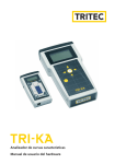
Characteristics Analyser
Hardware Operating Instructions
Contents
1 Introduction..................................................................................................................................3
2 Contents of the case.....................................................................................................................4
3
4
5
Warnings – Please mind!..............................................................................................................4
3.1 TRI-KA...................................................................................................................................4
3.2 Cables...................................................................................................................................4
3.3 Location................................................................................................................................5
3.4 Measurements......................................................................................................................5
Step by step to the measurement result.....................................................................................5
Connection of the photovoltaic generator.................................................................................6
6
7
8
9
10
11
TRI-SEN..........................................................................................................................................7
6.1 Cell temperature measurement..........................................................................................8
6.2 Irradiation measurement....................................................................................................9
TRI-KA..........................................................................................................................................10
7.1 Uoc – measurement of open-circuit voltage and short-circuit current..........................12
7.2 P Measur – characteristics measurement..........................................................................13
7.3 Sensor – communication with the TRI-SEN......................................................................13
7.3.1Current – display of the current irradiation and temperature values............................14
7.3.2Add – transfer of recorded irradiation and temperature values....................................14
7.3.3PC – transfer of measured values from the TRI-KA to the PC.........................................14
7.4 Memory – display of stored curves...................................................................................15
7.5 Setup – TRI-KA parameters...............................................................................................15
7.6 Storage / maintenance TRI-KA..........................................................................................16
Requirements for measurement and analysis...........................................................................16
Evaluation of the measurement results....................................................................................16
Declaration of conformity..........................................................................................................19
General terms and conditions of warranty for TRITEC products.............................................20
1 Introduction
The photovoltaic market is a highly active and brisk market. For end users, the annual energy
yield of photovoltaic installations is ultimately decisive. Previously, the quality control of installed
PV generators has only been possible with very expensive and unmanageable measuring systems.
The combined ”TRI-KA“ and ”TRI-SEN“ measuring system enters the market with easy-to-handle
mobile instruments of an excellent price/performance ratio offering any installer the possibility
for the quality control and the documentation of PV installations.
”TRI-KA“ and ”TRI-SEN“ are an intelligent measuring and documentation system which is indispensable for the professional installation and maintenance of PV installations. It facilitates the
proper assembly of a PV installation and provides comprehensive documentation of the quality
of the same.
The system performs the following measurements and analyses:
•
•
•
•
•
•
Open-circuit voltage
Short-circuit current
I-U characteristics
Module plane irradiation
Cell temperature
STC characteristics
The quality of a photovoltaic installation may be assessed by current-voltage characteristics. The
TRI-KA takes this measurement starting at a voltage of 50 V. In addition, the TRI-KA calculates
the output of the PV installation under STC conditions based on the measured values.
The measuring system is based on two portable instruments: the TRI-KA and the TRI-SEN. The
TRI-SEN measures the cell temperature and irradiation. The TRI-KA records current-voltage characteristics and can display short-circuit current and open-circuit voltage at the push of a button.
For the conversion of the characteristics into standard test conditions, the measured data is transferred from the TRI-SEN to the TRI-KA via an infrared interface. This data transfer procedure
enables the synchronous measurement of characteristics and solar irradiation irrespective of the
location.
The TRI-KA shows the output on an LC display which is able to provide graphic representation.
The measurement may be taken without any profound skills in measuring technology. The menu
navigation is logically structured and easy to understand.
2 Contents of the case
1 3
1 TRI-KA characteristics analyser
with infrared interface
6
5
2
4
2
3
4
5
6
7
TRI-SEN
Irradiation and temperature sensor with
memory and 2 interfaces (infrared and
USB-PC interface)
2 measuring cables:
1 red positive cable
1 black negative cable
1 USB cable
Batteries for the TRI-KA:
4 x LR6 / Mignon / AA
Battery for the TRI-SEN:
1 x 6LR61 / E-block / 9 V
1 CD with PC software (not shown)
The CD provided in the case contains a help file for the PC software.
System requirements:
Windows 2000® or Windows XP®
USB interface 1.0 or higher
Recommended: min. resolution of 1024 x 768 pixel, colour printer
3 Warnings – Please mind!
3.1 TRI-KA
The TRI-KA may only be used for photovoltaic generators of maximum 1000 Volt and 10 Ampère
direct current. Solar modules generate current and voltage as soon as they are exposed to light.
This means that also in overcast rainy weather, plugs and other voltage-carrying items represent
a danger! Therefore, all safety regulations must be strictly complied with while working on photovoltaic generators.
Improper handling is considerably prone to accidents and might cause severe injuries. Sources of
current and voltage other than solar modules can destroy the measuring instrument.
3.2 Cables
The connecting cables must NEVER be detached during measurement. The resulting arcs might
cause severe injuries and would destroy the contacts of the plugs.
3.3 Location
Measurements must not be performed in the vicinity of combustible gases and dusts or other
flammable materials. – EXPLOSION HAZARD !
The TRI-KA must not be used in rain or a wet or very moist environment because of the danger
of an electric shock. Liquid must not penetrate the device. Wetness and moisture destroy the
device. The tolerable TRI-KA temperature ranges between 5 and 50 °C. The TRI-KA should not be
exposed to direct sunlight for extended periods.
3.4 Measurements
Measurements may only be performed by skilled electricians. Read the user manual completely
prior to first commissioning of the device in any case. Store the manual together with the instrument.
The device may only be opened and repaired by authorised and trained persons. Disconnect all
connections to the solar generator and switch off the instruments prior to any opening of the
device (e.g. to change the battery).
All loads (e.g. inverters) must be disconnected from the solar energy installation prior to any
measurement. For measurements on a roof, all safety regulations concerning work on a roof and
on electric installations must be respected.
Safety first!
4 Step by step to the measurement result
The step-by-step instruction from the measurement to the PC:
Step
Explanations
1.
Disconnect loads from
the solar modules
All loads like inverters or batteries must be disconnected
from the solar modules prior to measurement!
2.
Measure the cell temperature using the TRI-SEN
See 6 TRI-SEN, 6.1 Measurement of the cell temperature
3.
Measure the irradiation
using the TRI-SEN
See 6 TRI-SEN, 6.2 Irradiation measurement
Solar modules
4.
Connect the TRI-KA to
solar modules
+
+
–
TRI -KA
Measuring cable
–
See 5 Connection of the photovoltaic generator
5.
Read open-circuit voltage and short-circuit
current if required
6.
Measure output
7.
Measure the cell temperature again (optional)
This step is recommended to receive an average tem-
perature value; see 6 TRI-SEN, 6.1 Measurement of the
cell temperature
8.
Transfer measured values from the TRI-SEN
to the TRI-KA via infrared interface
See 7 TRI-KA, 7.3 Sensor, 7.3.2 Add
9.
Transfer of measured values from the TRI-KA
via the TRI-SEN to the PC
See 7 TRI-KA, 7.1 Uoc
See 7 TRI-KA, 7.2 P Measur
Infrared
TRI -KA
USB cable
TRI -SEN
See 7 TRI-KA, 7.3 Sensor, 7.3.3 PC
5 Connection of the photovoltaic generator
For a significant informational value of the measurement it is crucial
that no solar module connected in parallel be measured. This would
lead to difficulties in the evaluation of the measurement results. The
individual strings can subsequently be added together by means of
the software.
During the measurement, the solar modules may only be connected
to the TRI-KA. Other loads like inverters or batteries must be disconnected from the solar modules! Please ensure the correct connection
of the poles. Reverse polarity might lead to errors and damage. The
measuring lines must be completely inserted into the sockets. Excessive junction resistance falsifies the measurement result and can cause
dangerous arcs and burns. Damaged measuring cables must be replaced immediately. The repair of cables is not permitted.
PC
6 TRI-SEN
The TRI-SEN is used to record the cell temperature and irradiation. After the characteristics
measurement by the TRI-KA these values may be transferred from the TRI-SEN to the TRI-KA and
used for the conversion into STC values (Standard Test Conditions: Irradiation 1000 W/m2, spectrum AM = 1.5 and module temperature 25 °C).
For a simple measurement of open-circuit voltage and/or short-circuit current the irradiation and
the cell temperature are not required.
3
1 2
4
7
5
1 Slide switch for start-up
2 Key for temperature measurement
3 Temperature sensor and infrared interface
4 LC display
5 Solar cell for irradiation measurement
6 USB-PC connection
7 Hinged back
6
TRI-SEN data
Measurement
Temperature measuring range
Irradiation measuring range
Measuring connection
Memory
LC display
Power supply
Interface
Operation
Evaluation
Dimensions
Weight
Cell temperature and irradiation
10 – 60 °C ± 3 %
100 – 1000 W/m2 ± 3 %
Non-contact
Up to approx. 8 hours (volatile)
8 characters, 5 x 7 pixels each
Battery operation (1 x 9 V) or USB interface
Infrared to the TRI-KA, USB to PC
Key
Transfer to the TRI-KA
130 x 75 x 40 mm
0.15 kg
The TRI-SEN is powered by a 9 V battery. If the device is stored for a longer period of time, it is
advisable to remove the battery from the device. If the TRI-SEN is operated in connection with a
PC, the power is supplied via the USB interface.
TRI-SEN change of battery
1. Remove protective cover (in case of a USB connection) pressing
both lateral buttons (e.g. with a pen).
2. Take out terminal connections and connect them to the bat-
3. Insert battery (terminals are pointing outwards) and close pro-
tery (6LR61 / E-block / 9 V).
tective cover.
6.1 Cell temperature measurement
The TRI-SEN is switched on using the slide switch on the left-hand side
of the device. A short beep and flashing of the irradiation value in the
LCD confirm that the device is available for operation. The upper end
of the TRI-SEN is equipped with a temperature sensor for non-contact
measurement. The sensor is pointed directly to a solar cell. As soon as
the temperature measurement key is pressed a beep is sounded and
the instrument acquires the temperature. Simultaneously, the currently measured temperature Ta appears on the LCD. This measurement
should be repeated at different points of the solar area. With every
new measurement a new average temperature Tm is calculated. If the
key is continuously pressed, the average temperature value Tm appears on the display. Tm is included in the conversion of the measured
characteristics into STC characteristics (see 7.3.2).
It is recommended to measure the lower, centre and upper solar cells
since a temperature difference between the upper and lower solar
cells exists. The average measured temperature value remains in the
memory until the device is switched off.
Once the TRI-SEN is switched off, all measured values are deleted!
6.2 Irradiation measurement
As soon as the TRI-SEN has been switched on by the slide switch, the
irradiation is measured via the integrated solar cell. After temperature
measurement, the solar cell of the TRI-SEN is positioned in the module
plane (i.e. at the same angle of inclination and parallel to the solar
module) using the hinged back. This positioning is decisive for the
accuracy of the STC evaluation.
Irradiation is continually measured and stored in the memory in
intervals. The device runs out of memory after 8 hours. The data has
to be transferred to the TRI-KA after measurement (see 7 TRI-KA, 7.3
Sensor) since it will be lost as soon as the TRI-SEN is switched off!
7 TRI-KA
5
4
TRITEC
TRI-KA
2
3
Characteristics
Analyser
V1.00 0524-1030
1
1
2
3
4
5
Info
Uoc
P Measur
Sensor
Memory
Setup
OFF
08:59
ON / Backlight key
OK key – operation of the selected menu
Arrow key(s)
LC display
Infrared and cable interfaces
TRI-KA data
Measurement
Voltage measuring range
Current measuring range
Measuring connection
Memory
LC display
Power supply
Interface
Operation
Evaluation
Dimensions
Weight
Options
Current-voltage curve (output, short-circuit current and open-
circuit voltage)
50 – 1000 V ± 2 %
0.1 – 10.0 A ± 2 %
Aligator clip (different adaptor cables as options)
Up to 125 measured curves (not volatile)
Graphic representation, 128 x 64 pixel, backlight via key
Battery operation (4 x 1.5 V)
Infrared to the TRI-SEN, 2 measuring cables to PV string
Menu driven via membrane keyboard
PC software (Windows 2000 and XP)
236 x 125 x 42 mm
0.5 kg
Adapter cable for MC3, MC4, Huber & Suhner and Tyco plug
The autonomous power supply and easy handling properties make the TRI-KA a fully portable
instrument which can be taken anywhere. If the device is stored for a longer period of time, it is
advisable to remove the batteries from the device.
The instrument has a red input for the positive cable and a black input for the negative cable of
a solar module series connection. An infrared interface for non-contact communication with the
TRI-SEN has been arranged at the top of the device.
10
TRI-KA navigation
ON / Backlight
Info
Uoc
OK
Measurement
Uoc & Isc
Return
P Measur
OK
Measurement of open-circuit
voltage and short-circuit current at the connecting ter-
minals – see 7.1
Measurement of I-U characteristics – see 7.2
Enter
parameters
Measurement of
characteristics
Return
Sensor
OK
Connection to the TRI-SEN
and the PC – see 7.3
Current
Autom.
Add
Manual
PC
Return
Memory
OK
Select
measurements
Display of stored measured
data – see 7.4
Return
Setup
OK
Change setup
Setting of instrument parameters – see 7.5
Return
OFF
11
TRI-KA change of battery
CAUTION: Prior to any battery change the cables must
be removed from the TRI-KA and the device must be
switched off (see Warnings)!
1. Remove protective cover (see picture) press-
2.
3.
4.
ing both lateral buttons (e.g. with a pen).
Take out the black battery compartment
pulling the side elements together.
Place the four batteries (LR6 / Mignon / AA) in
the battery compartment.
Push the battery compartment (opening
points to the rear side of the TRI-KA) back into
the TRI-KA until it engages and replace the
protective cover.
7.1 Uoc – measurement of open-circuit voltage and
short-circuit current
The TRI-KA can measure and display the current
open-circuit voltage (Uoc). The present closed-circuit current (Isc) can be measured in the same menu
item, if required. These values can neither be stored
nor recorded. If required, these values must be written down. Both measurements serve the fast evalu-
ation of the photovoltaic generator in the field. The
instructions concerning the connection of the solar
modules must be respected.
Measurement of open-circuit voltage and short-
circuit current:
1. Ensure that the TRI-KA has been correctly
connected to the photovoltaic generator to
be measured.
2. Switch on the TRI-KA by pressing the ON /
Backlight key.
3. Select the Uoc menu item using the arrow
keys.
4. Press the OK key to open the Uoc menu.
5. Read open-circuit voltage.
6. If required, press any arrow key to read the
closed-circuit current.
12
98.5 V
To view short-circuit
current press any
arrow key
Uoc
[Return]
7.2 P Measur – characteristics measurement
For characteristics measurement the cell tempera-
ture must be measured first and the TRI-SEN must
be placed in the module plane for the irradiation
measurement. Subsequently, the curve can be re-
corded in the P Measur menu.
For a complete characteristics measurement proceed
as follows:
1. Ensure that the TRI-KA has been correctly
connected to the photovoltaic generator to
be measured.
2. Switch on TRI-KA pressing the ON / Backlight
key.
3. Select the P Measur menu item using the
arrow keys.
4. Press the OK key to get into the P Measur
menu.
5. Define object number, installation number,
string number for unambiguous recognition.
Parameter settings may be changed using the
arrow keys. (The increment function is helpful
for the measurement of large installations.
The string number is increased by 1 after each
measurement.)
6. Select the Start menu level and trigger the
measurement using the OK key.
7. Measurement is performed.
8. The measured curve is recorded and simul-
taneously displayed.
9. Leave the illustration using the OK key.
Parameters for measurement
Object No.: 0001
Installation No.: 1
String No.: 1
Auto-increment: [Yes]
[Start]
[Return]
I
Isc: 2.4A
Uoc: 77V
1A
20V
If the voltage is too low, a measurement cannot be
performed. Please check the messages on the display.
The measurements are stored in the memory under a
running number. 125 curves can be stored.
V
Measur points: 94
[Return]
7.3 Sensor – communication with the TRI-SEN
The Sensor menu item is used to transfer measured
values from TRI-SEN to TRI-KA and for the communication between TRI-KA and the PC.
13
7.3.1 Current – display of the current irradiation
and temperature values
The TRI-SEN can display the currently measured values
for the verification of irradiation and temperature:
1. Navigate to Current in the Sensor menu.
2.
3.
Point the upper ends of both devices against
each other so that the infrared communica-
tion can take place.
Read measured values.
7.3.2 Add – transfer of recorded irradiation and
temperature values
After the characteristics measurement the irradiation
and temperature values may be transferred from the
TRI-SEN to the TRI-KA in the Add menu point. This can
be done automatically (time-dependent) or manually (independent allocation of values). The measured
characteristics are converted into STC characteristics
using the sensor data. The same can immediately be
seen on the display or analysed by the PC software.
1.
2.
3.
Select the Add menu item.
Select Autom. for an automatic transfer of
measured values.
Point the upper ends of both devices against
each other so that the infrared communica-
tion can take place.
If the automatic transfer does not work or is not
desired, the values for irradiation and temperature
may be entered in the Manual menu using the arrow
keys. Characteristics may also be acquired without re-
cording the irradiation and temperature, however,
this will not guarantee a correct analysis.
7.3.3 PC – transfer of measured values from the
TRI-KA to the PC
1. Switch on the TRI-KA and the TRI-SEN and
start the TRI-KA software.
2. Point the upper ends of the TRI-KA and the
TRI-SEN against each other so that the infra-
14
Current values:
Temp.: 19°C
Sun: 1003W/m2
Batt. V.: 7.5V
USB V.: 0.0V
Unit No.: 0524-1006
Current
Add
PC
[Return]
3.
4.
red communication can take place.
Connect the TRI-SEN with the PC using the
provided USB cable.
Select the Sensor menu item.
5. Select the PC menu item.
6. Download the measured values to the PC (see
operating help software on the CD).
7.4 Memory – display of stored curves
All of the stored curves may be displayed in the
Memory menu item. All relevant values can be seen
on the right-hand side of the display:
• Date and time of the measurement
• Irradiation and temperature
• Peak output at STC (i.e. nominal output con-
verted into STC)
• Filling Factor (FF) refers to the quotient of
the maximum output of a solar cell at the
maximum power point and the product of
open-circuit voltage and closed-circuit cur-
rent
• Measurement number (the left and right
arrow keys select the next or previous
measurement; <05/12> means that this is the
5th of 12 measurements)
• Closed-circuit current measured and extrapo-
lated to STC
• Open-circuit voltage measured and extrapo-
lated to STC
7.5 Setup – TRI-KA parameters
The following TRI-KA parameters may be adjusted in
Setup:
Time
• Time
• Date
Display
• Language: English, French, German, Italian or
Spanish may be selected
• Contrast
• Shutdown time for automatic shutdown
I
1A
20V
U
6.5 > 7.9A / 100V > 110V
22.06.05
14:16:09
819 W/m2
47 °C
P: 651W
FF: 0.74
<05/12>
[Return]
TRI-KA parameters
Display
Language: English
Contrast: 172
Shutdown time: 5 min.
Key sound: [No]
Auto. backlight: 0 sec.
[Return]
15
• Key sounds for the confirmation of an operation
• Auto. Backlight
Memory
• Delete all?: If the memory is deleted, all data and curves are irretrievably deleted!
7.6 Storage / maintenance TRI-KA
The TRI-KA must be transported and stored its case. The instrument must not be exposed to direct
sun irradiation in prolonged measuring. The membrane keyboard must not come in contact with
pointed or sharp objects. The keys are intended for manual operation and not resistant against
metals or other hard materials. The instrument may only be cleaned with a soft cloth. Abrasives
or aggressive cleaning agents destroy the glass of the LCD and the membrane keyboard.
8 Requirements for measurement and analysis
Weather conditions should be constant during measurement. Measurements taken under
strongly fluctuating weather conditions will be insignificant. The stronger the irradiation, the
more accurate the measurement will be. From approx. 400 W/m2 onwards a measurement is
significant. An irradiation of more than 500 W/m2 is however recommended. The temperature
measurement is selective and inconsistent for an entire solar installation. When using several
strings, the temperature difference between the lower and the upper string will be substantial.
The environment of the solar modules may have a strong influence on the temperature. Try to
collect an average value as significant as possible.
Make sure that the TRI-SEN is lying in the module plane (same alignment and same inclination as
the solar modules). Even small deviations will result in substantial measuring errors.
Measurements may be repeated for an improved evaluation. The evaluation software allows
several measurements for the same serial connection.
9 Evaluation of the measurement results
Using the current-voltage characteristics (I-U characteristics) of a PV generator, different properties and problems of the generator can be recognised and analysed. Partial shading of the
generator field, defect bypass diodes, delamination of individual PV modules, excessive serial resistance of the modules, dirty modules and problems of individual cells can be recognised in this
way. The interpretation of the characteristics requires some experience and a basic knowledge
of semiconductor engineering. To facilitate the interpretation, some examples of characteristics
taken from the evaluation software are subsequently listed.
16
• Good string
• Partial shading of the entire string
• Covered cells of a module
17
Generally, it is true to say that the temperature influences the width (Uoc) and the irradiation
influences the height (Isc) during the conversion of the I-U characteristics into the STC characteristics.
Using the I-U characteristics, the solar irradiation and the module temperature, the TRI-KA
calculates the electric values of the PV generator under STC conditions. STC = Standard Test
Conditions = Conditions under which PV modules reach their values stated on the rating plate
(standard test conditions: irradiation 1000 W/m2, spectrum AM = 1.5 and module temperature
25 °C). Using the calculated peak performance at STC the actual output can be compared with
the output stated on the data sheets of the modules. The installation of the PV generator and
the condition of PV modules can be evaluated by a comparison of the actual peak output at STC
and the output according to the data sheet. In case of unclear characteristics or insufficient peak
output at STC, please contact the manufacturer of the components concerned to obtain further
information in relation to the components and possible errors.
The software is included in the delivery of the TRI-KA. Furthermore, it can be downloaded from
www.tritec-energy.com.
18
10 Declaration of conformity
19
11 General terms and conditions of warranty for TRITEC products
TRITEC products are of top quality and exclusively available via specialised retail outlets. TRITEC
warrants unobjectionable functioning and faultlessness of its devices in the EU at the time of
delivery. If our products are used correctly, the warranty period shall be two years after their
purchase. The delivery note or original invoice shall be the proof of dispatch or delivery.
However, should problems or deficiencies occur, we recommend the following procedure:
• Visit our website. You will find a repair form as well as the current addresses of our branches
world-wide under Service & Support.
• Contact your outlet or the next TRITEC branch.
TRITEC is very concerned about warranting product quality and will provide any support and
expert advice to you to this end.
Warranty
• TRITEC warrants that its products will function properly for a period of two years after
purchase if operated correctly.
• The warranty covers the costs of repair, replacement devices and/or the replacement of
damaged parts. Any costs relating to the assembly, the dispatch or travels of technicians are
not included and shall be charged in accordance with the expenditure incurred.
• The warranty shall lapse in case of improper use of TRITEC products, e.g. improper installa-
tion or maintenance, replacement or changes which were not authorised by TRITEC.
• In case of delivery by TRITEC, the goods shall be checked immediately after receipt. Transport
damage shall be reported within 5 days.
• For transport damage as well as any other damage caused after the passage of risks any lia-
bility shall be excluded.
Notice
Because of the large available number of different module types and brands and the dynamic
technical development, TRITEC cannot guarantee that all modules, which are available at the
market place, can be measured. Off course we do our utmost to keep fully on track with all
developments to achieve a full market coverage a.s.a.p.
20
Returns for repair purposes
All of the returns shall be co-ordinated by your TRITEC representation/branch in your vicinity.
Please contact your customer consultant.
All returns shall be subject to the following conditions:
• A registration number (RMA number) which entitles you to return the materials. RMA
numbers may be applied for at your branch.
• You shall bear the postage fees for all returns.
Your TRITEC branch will be at your disposal for any queries you might have. Report first to this
branch.
The exclusive place of jurisdiction for all disputes with TRITEC arising from the contract, illicit
action or any other legal reason shall be Basel, Switzerland, in the absence of contradictory,
written understandings and as far as legally permitted.
Made in
Switzerland
© Version 070827-9e | The German version is binding
Subject to change without notice
21
Your notes
www.tritec-energy.com | [email protected]