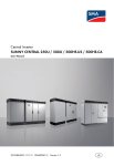
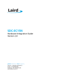
1
Operating
instructions TRI-KA
• User-friendly display
• Large input range for current
and voltage
• Pleasantly handy
• Wireless connection to the sensor
Contents
1. Overview
1.1 Changing the TRI-KA language setting
4
1.2 Introduction
5
1.3 Scope of delivery
6
2. Warnings
2.1 TRI-KA
7
2.2 Measuring cables
7
2.3 Location
7
2.4 Measurements
8
3. Measurement and analysis requirements
9
4. Instrument preparation and operation
4.1 Charging the batteries
10
4.2 Inserting the memory card
10
4.3 Connecting the TRI-KA
10
4.4 Connecting the TRI-SEN to the solar module
11
4.5 Switching on the instruments
11
5. Taking a measurement 12
6. TRI-KA – Overview
6.1 Case and control elements
14
6.2 Technical data
14
6.3 Programme structure
15
6.4 Layout of the customer and system structure
16
6.5 Display layout
16
7. TRI-KA – Functions
7.1 Power measurement
17
7.2 Actual values
23
7.3 Memory
24
7.4 Settings
27
8. TRI-SEN – Overview
8.1 Case and control elements
32
8.2 Technical data
32
9. TRI-SEN – Functions
9.1 Overview
33
9.2 Measuring the cell temperature
33
9.3 Measuring the irradiation
34
9.4 Measuring the angle of inclination
34
10. Transfer of measuring data
10.1 Transfer of TRI-SEN data to the TRI-KA
35
10.2 Transfer of TRI-KA values to the PC
35
10.3 Evaluation of the measuring results
36
11. Instructions for use 11.1 Instrument storage and care
37
11.2 Disposal
37
12. Declaration of conformity
38
4_Overview
1. Overview
1.1 Changing the TRI-KA language setting
1. Press the On/Off button to start the TRI-KA.
2. Click on Settings.
3. Press the Display button Display.
4. Select the preferred language from the language
drop-down list Language.
5. Click on the Settings and Home button to return to the
main menu.
Overview_5
1.2 Introduction
Photovoltaics are a fiercely competitive market. The primary focus
of the end user is on the annual energy yield of their photovoltaic system. The TRI-KA characteristics analyser with the wireless
TRI-SEN stands out due to its simple operation, its flexible mobility and its excellent price-performance ratio. It provides installers
with a quality control system for documentation of their PV
system data.
The TRI-KA with the TRI-SEN is an intelligent measuring and
documentation system that is indispensable for a professional
installation and maintenance of a PV system. It facilitates the
correct installation of a PV system and allows a comprehensive
documentation of the system quality.
The measuring system is based on the two portable measuring
instruments TRI-KA and TRI-SEN. It can be used to carry out the
following measurements and analyses:
TRI-KA
• Open-circuit voltage UOC
• Short-circuit current ISC
• I/U characteristic curve
• MPP voltage UMPP
• MPP power IMPP
• MPP output PMPP
• STC characteristic curve
• STC values
• Fill factor
• Ideal characteristic curve of module manufacturer
TRI-SEN
• Global irradiation at module level
• Cell temperature
• Angle of inclination
To convert the characteristic curves under standard test conditions, the measured data are wirelessly transferred from the
TRI-SEN to the TRI-KA. This data transfer process enables a synchronous measurement of the characteristic curves and the solar
irradiation irrespective of the location.
6_Overview
1.3 Scope of delivery
• 1 TRI-KA
• 1 TRI-SEN
• 1 hard case with foam padding
• 1 TRI-KA measuring cable set (MC3, MC4, Huber+Suhner, Tyco,
SunClix and without connectors)
• 1 TRI-SEN mounting
• 1 SD card (PC user software with user guide)
• 1 USB SD/SDHC card reader
• 2 power supply units (chargeable)
• 1 operating instructions
The following are minimum requirements for optimal use of the
PC software.
System requirements:
• Microsoft® Windows XP/ Vista/7
• Pentium processor with at least 600 MHz or equivalent
• at least 256 MB of RAM or higher
• VGA graphics card with at least 16 bit colour setting
(High Color) and a resolution of 1024 x 768 pixels
• at least 500 MB of free hard disc space
• keyboard; mouse
• USB interface
Warnings_7
2. Warnings
2.1 TRI-KA
The TRI-KA characteristics analyser should only be used for photovoltaic systems with a maximum DC voltage of 1000 V and a
direct current of 15 amp. Solar modules exposed to sunlight produce voltage and current. The connectors and other live parts may
pose a risk of high voltage even under cloudy conditions and diffuse irradiation!
When working on photovoltaic systems, it is vital that the following safety regulations are observed!
Improper handling of the system can lead to serious accidents and
injury. Power or voltage sources other than solar modules may
irreparably damage the measuring instrument.
2.2 Measuring cables
Do not disconnect the measuring cables during measurements!
The resulting electric arcs may cause serious injury and irreparably
damage the plug connectors and the measuring instrument.
2.3 Location
Do not use the characteristics analyser for measurements near
combustible gases and dust or other flammable materials. Risk of
explosion!
Do not use the device in rain or under wet or very humid conditions due to the risk of electric shocks. Prevent liquid from penetrating into the device, as this may cause irreparable damage. The
permissible ambient temperature range for the TRI-KA is between
0 and 50 °C. Do not expose the TRI-KA to long periods of direct
sunlight.
8_Warnings
2.4 Measurements
Measurements on photovoltaic systems should only be carried out
by properly trained electricians! Carefully read the user manual
before using the instrument. Keep the manual with the measuring instrument. The devices should only be opened and repaired
by the manufacturer.
Before taking a measurement, disconnect all loads (e.g. inverters,
etc.) from the photovoltaic system.
When using the device on a roof make sure to comply with all
safety regulations relating to roof work as well as with the requirements for working on electrical equipment!
Measurement and analysis requirements_9
3. Measurement and analysis requirements
The weather conditions must remain constant throughout the
measuring process. Significant changes in the weather will produce unreliable results of the characteristic curve measurement. Measurements are reliable from an irradiation of approx.
500 W/m2. The higher the irradiation, the more accurate the characteristic curve measurement.
The module temperature is measured at various points rather
than in a fixed place for a whole solar system. Where there are
several rows of solar modules, the temperature between the upper and lower rows varies quite considerably. The environment of
the solar modules can have a significant influence on the temperature. Several temperature measurements on the modules of the
string to be measured produce the most reliable average.
The TRI-SEN is placed in the mounting and fitted to the module
frame. It must face in the same direction and have the same inclination as the solar modules to be measured. Even small deviations
can lead to significant errors in measurement and so distort the
results.
To ensure optimal system analysis, it is advisable to repeat the
measurements. The evaluation software allows several measurements for the same string. In order to produce reliable measuring
results, it is advisable to expose the TRI-SEN to the measuring conditions over a longer period.
10_Instrument preparation and operation
4. Instrument preparation and operation
4.1 Charging the batteries
Both the TRI-KA and the TRI-SEN integrate a powerful lithium
polymer battery. It is recharged using the power supply units provided for uncomplicated working without inconvenient cables.
The jack to plug in the charger is found on the underside of each
device.
The status of the battery is shown on the instrument screen. Further instrument information on the current battery voltage is provided in the menu under Settings > Info.
4.2 Inserting the memory card
The data between the characteristics analyser TRI-KA and the PC
software are communicated via the SD memory card. This is included in the delivery and needs to be inserted before the TRI-KA
is switched on. The memory card slot is found on the underside of
the measuring instrument.
4.3 Connecting the TRI-KA
When measurements are taken with the TRI-KA, the solar modules must only be connected to the measuring instrument.
Other loads such as inverters, chargers, etc., must be disconnected
from the solar modules. Failure to do so may result in irreparable
damage to the measuring instrument!
Make sure to connect the measuring cables correctly to the modules. Reverse polarity may damage the instrument. The measuring
cables must be fully inserted into the connectors. Excessive contact resistance will falsify the results of the measurement and
cause hazardous arcs and burns.
Damaged measuring cables must be replaced immediately. Do
not attempt to repair the cables.
Instrument preparation and operation_11
4.4 Connecting the TRI-SEN to the solar module
The TRI-SEN is placed into the TRI-SEN mounting fitted to the
module frame of an edge module of the photovoltaic system.
The mounting is slotted onto the side of the module frame. The
two clamps are positioned on the frame by turning the fixing
screw and then clamped down by tilting the lever.
The mounting is now securely fitted to the module and the
TRI-SEN can be placed into the mounting.
4.5 Switching on the instruments
The instruments are switched on using the On/Off button. Once
switched on, the display is activated. The TRI-SEN signals readiness
for operation with a short beep.
Before the instruments are switched on, make sure that the
battery has been charged (chapter 4.1). For the TRI-KA it is also
important to remember that the SD memory card must first be
inserted. The SD card stores the measured data. The customer and
module database is also kept on the SD card.
The instruments are switched off again by pressing the On/Off
button. The display goes out once the instruments are switched
off.
12_Taking a measurement
5. Taking a measurement
The steps
Measuring the module temperature at several points of the string
or module to be measured (chapter 9.2).
Fitting the TRI-SEN mounting to the module to be measured and
measuring the irradiation (chapter 9.3).
Using the TRI-KA to measure the open-circuit voltage (UOC ) and
the short-circuit current (I SC ) and determine the system’s current/
voltage characteristic curve (chapter 7.1).
Wireless transfer of the measured data from the TRI-SEN to the
TRI-KA during and after measurement (chapter 10.1).
Importing the measured results via SD card from the TRI-KA into
the PC and evaluating them using the software provided (chapter
10.2).
Taking a measurement_13
14_TRI-KA – Overview
6. TRI-KA – Overview
6.1 Case and control elements
1
1. Touch screen to operate the TRI-KA
2. Power button to switch the TRI-KA on and off
3. Measuring cable connection, positive terminal
4. Measuring cable connection, negative terminal
5. Memory card slot
6. Plug-in point for the charger cable
2
3
4
5
6
6.2 Technical data
Measuring
Calculated values
Voltage measuring range
Current measuring range
Measuring connection
Memory capacity for
measuring curves
Display
Power supply
Interface
Ambient temperature
Protection mode
Measuring category
Dimensions (L / W / H)
Weight
Norms
Current/voltage, short-circuit
current, open-circuit voltage
STC values (short-circuit current, open-circuit voltage, MPP current,
MPP voltage), MPP output, fill factor,
ideal characteristic curve of module
manufacturer
1.0 – 1000 V (<±1%)
0.1 – 15.0 A (<±1%)
Measuring cable
Depending on size of SD memory card
(>1000 measured curves with 1 GB)
3.2 inch colour LCD touch screen
(240 x 320 pixels, RGB)
Lithium polymer battery
2 measuring cables to PV string,
wireless connection to TRI-SEN,
SD/SDHC memory card for PC
0 – 50 °C
IP20
CAT II 1000 V, CAT III 600 V
210 / 105 / 41 mm
0.5 kg
IEC/EN 61010-1, CE mark
TRI-KA – Overview_15
6.3 Programme structure
The following chart provides an overview of the programme and
operating structure of the TRI-KA. For further information on the
functions of the TRI-KA refer to chapter 7 TRI-KA – Functions.
16_TRI-KA – Overview
6.4 Layout of the customer and system structure
The measured data are stored on the SD card and hierarchically
managed in the TRI-KA measuring instrument and the PC software.
To each hierarchy level can be added any number of further levels. The levels can be given any name. The measured data are
saved in the relevant strings.
The hierarchy levels can be created in the PC software and then
selected in the TRI-KA or directly entered in the TRI-KA.
1
5
2
3
4
6
6.5 Display layout
General information about the measuring instrument and the
currently open window is shown at the top and bottom of the
screen:
1. Battery status
> shows the remaining battery charge
2. Wireless connection
> shows whether a wireless connection to the TRI-SEN exists
3. Progress indicator
> shows instrument activity and progress
4. Date/ Time
> shows the date and time set for the instrument
5. Navigation indicator
> shows which TRI-KA window is open. In the Home screen,
it shows the instrument’s serial number.
6. Firmware number
> is shown in the Home screen
TRI-KA – Functions_17
7. TRI-KA – functions
7.1 Power measurement
Press the Power Measurement button to start measuring the current /voltage characteristic curve.
The process progress is shown in the bottom part of the screen.
The two arrow keys allow navigation to the previous and the next
step. The Home button takes you back to the main menu.
Window 1 / 7 & 2 / 7 – PV data 1 & 2
Selection or entry of customer and system data on the photovoltaic system to be measured.
18_TRI-KA – Functions
Selecting a text field opens a window in which existing data or
details previously created using the PC software and stored on the
memory card can be selected.
To enter new data, press the + button next to the text field.
Depending on the entry field, a window opens with the appropriate entry options.
To change from full keyboard mode to numerical keypad, click on
the numerals.
The entry is confirmed by clicking on the tick symbol. The instrument automatically returns to the previous menu function.
TRI-KA – Functions_19
To move to the next window after the customer and system data
have been entered, click on the right arrow at the bottom of the
screen.
Window 3 / 7 – Correction voltage loss cables
Correction of the measuring result with the voltage loss in the PV
cable between the modules and the measuring instrument.
The correction is activated and deactivated in the first line. Data
to calculate the cable voltage loss are entered in the following
fields.
20_TRI-KA – Functions
Cable cross-section
> Cross-section of the PV cable
Length A
> Length of the cable between the measuring instrument and
the first module of the string
Length B
> Length of the cable between the measuring instrument and
the last module of the string
Specific resistance
> Specific resistance of the cable used. Exact data are available
on the data sheet of the manufacturer.
Standard values
> Copper: 0.01786 Ω*mm²/m
> Aluminium: 0.02857 Ω*mm²/m
TRI-KA – Functions_21
Window 4 / 7 – Measurement of the current/voltage
characteristic curve
Before the characteristic curve is measured, the measuring range
is established. While the characteristic curve is measured, the current and voltage values currently measured are shown on the
screen and the characteristic curve is drawn. The screen also shows
the irradiation measured by the TRI-SEN. The right value is the average irradiation established; this is used for STC extrapolation.
If no wireless connection can be established between TRI-KA and
TRI-SEN during measurement of the characteristic curve, the data
are temporarily stored in the TRI-SEN. After the measurement(s),
the data stored in the TRI-SEN must be synchronised with the
TRI-KA (chapter 10.1).
22_TRI-KA – Functions
Window 5 / 7 – TRI-SEN data
At this point, the module temperature can once again be measured with the TRI-SEN.
If no wireless connection can be established between TRI-KA and
TRI-SEN during measurement of the characteristic curve, the data
are temporarily stored in the TRI-SEN. After the measurement(s),
the data stored in the TRI-SEN must be synchronised with the
TRI-KA (chapter 10.1).
Window 6 / 7 – Save measurement
The measured data are saved on the inserted SD card. Once successfully saved, click on the tick symbol or the right arrow to open
the next window.
Window 7 / 7 – Display of the characteristic curve
The diagram shows the characteristic curve previously measured
and extrapolated to STC along with the ideal characteristic curve
of the manufacturer.
If no module was selected under the module data (window 2 / 7),
the ideal characteristic curve of the manufacturer is not shown. If
no TRI-SEN data could be stored, the measured characteristic
curve extrapolated to STC is not shown.
Click on the Home button to complete the measurement and return to the main menu.
TRI-KA – Functions_23
7.2 Actual values
Click the Actual Values button to see the actual values of the
TRI-KA and TRI-SEN.
Uoc
Isc
Actual values – TRI-KA
This shows details of the open-circuit voltage and short-circuit
current. Click the ISC button on the screen to measure the shortcircuit current.
Use the TRI-SEN or TRI-KA button to change from the actual values of the TRI-KA to the TRI-SEN or vice versa. Click the Home
button to return to the main menu.
24_TRI-KA – Functions
Actual values – TRI-SEN
Shows the current irradiation, the average module temperature
measured along with the number of temperature measurements
taken and the angle of inclination of the TRI-SEN.
7.3 Memory
Measurements stored on the SD card can be accessed using the
Memory button.
TRI-KA – Functions_25
Open saved data
Select the customer, the system, the inverter or the name of the
string to retrieve the data stored.
Switch between saved measurements
Use the arrow keys to change between further measurements
stored in the selected string. Touching the left or right side of the
screen next to the characteristic curve will also let you browse
through the stored measurements in the selected string.
Click the Home button to return to the main menu.
Press the Info button to see further information on the selected
measurement.
26_TRI-KA – Functions
Show more data
The Info screen provides further data on the selected measurement.
Click the Home button to return to the start screen.
To see a graphic representation of the selected measurement click
the graph button in the middle.
The Delete button deletes the measurement data. This step must
be confirmed in the next step.
Add missing data
Missing TRI-SEN data in saved measurements are indicated by
the number of missing data shown at the top left edge of the
Memory button.
Click on the TRI-SEN button to synchronise the TRI-SEN data with
the TRI-KA.
TRI-KA – Functions_27
7.4 Settings
The basic settings of the TRI-KA can be changed under Settings.
28_TRI-KA – Functions
Set time and date
Click on the clock symbol to set both the time and the date of the
instrument.
The time and date are changed in the appropriate input fields using the numerical keypad.
Language and display settings
Display and instrument settings are made by clicking on the
screen symbol. This is also where the TRI-KA language can be
changed.
Set backlight
The brightness of the display backlight can be set in four stages.
Auto switch-off automatically switches the device off after the set
time. Switch-off times range from 1 to 15 minutes. This function
is deactivated with the Off button.
TRI-KA – Functions_29
Change display background
Use the right button at the bottom of the screen to change between a black and white background. Press the gear button to
return to the Settings screen.
Show memory space and format SD card
Click on the Memory button to view the memory available on the
inserted SD card.
The memory card in the TRI-KA is formatted under Memory Card
Settings. Once the formatting has been confirmed, all data on the
memory card are deleted.
Set minimum irradiation
The monitoring values for the power measurement are changed
in the Data submenu. If the current level of irradiation falls below
the set value, the measurement is aborted resulting in an error
message.
30_TRI-KA – Functions
Set irradiation tolerance (%)
Maximum permitted variation in irradiation (as a percentage)
during measurement of the characteristic curve. If the irradiation
exceeds the tolerance value, the measurement is aborted resulting in an error message.
Device information and firmware update
Press the Info button to check the serial number, the software version and the battery status of the TRI-KA and TRI-SEN.
If the Firmware Update button is highlighted in yellow, a new
firmware version for the TRI-KA is available on the SD card. Click
the button to install the new firmware.
Use the TRI-SEN / TRI-KA buttons to change between TRI-SEN and
TRI-KA data. Click the gear button to return to the Settings menu.
TRI-KA – Functions_31
32_TRI-SEN – Overview
8. TRI-SEN – Overview
8.1 Case and control elements
1
2
3
4
1. Button to measure the temperature
2. Display to read the current and measured values
3. Polycrystalline cell for irradiation measurement
4. Monocrystalline cell for irradiation measurement
5. Power button to switch the TRI-SEN on and off
6. Temperature sensor
7. Plug-in point for the charger cable
5
6
7
8.2 Technical data
Measuring
Temperature measuring range
Irradiation measuring range
Measuring connection
Reference cells
Memory Display Power supply
Interface Ambient temperature
Protection mode
Dimensions (L / W / H)
Weight
Norms
Global irradiation, module
temperature, angle of
inclination
0 – 100 °C
(± 3% in relation to a
black body)
100 – 1200 W/m2 ± 5%
Non-contact measurement
1 x monocrystalline cell,
1 x polycrystalline cell
Up to approx. 8 hours (volatile)
B/ W LC display
(2-line, 16 characters)
Lithium polymer battery
Wireless connection to TRI-KA
(Range depends on local and physical conditions.)
0 – 60 °C
IP20
160 / 82 / 41 mm
0.2 kg
CE mark
TRI-SEN – Functions_33
9. TRI-SEN – Functions
9.1 Overview
The TRI-SEN measures the irradiation, cell temperature and angle
of inclination. The measured data are wirelessly transferred directly to the TRI-KA. The data are used to convert the characteristic curve measured by the TRI-KA into a STC characteristic curve.
(STC – Standard Test Conditions: irradiation 1000 W/m2, spectrum
AM = 1.5, module temperature 25°C).
If no wireless connection can be established between the TRI-KA
and TRI-SEN during measurement of the characteristic curve, the
data are temporarily stored in the TRI-SEN and must subsequently be synchronised with the TRI-KA (chapter 10.1).
The irradiation and cell temperature are not necessary for simple
measurements of the open-circuit voltage and/or short-circuit current.
9.2 Measuring the cell temperature
When switched on, the TRI-SEN signals its readiness for operation
with a short beep. The TRI-SEN has a temperature sensor at the
top end for contactless measurement of the cell temperature. The
sensor is held directly onto a solar cell.
Press the °C temperature measurement button for at least one
second until you hear a beep indicating that the device is now
measuring the temperature.
The measured temperature is shown on the screen while the °C
button is pressed. When the temperature button is released, the
screen changes to the average temperature of the measurements
taken. The number of measurements is shown in brackets. It is
recommended to measure the temperature at least 3 times before measuring the characteristic curve and at least 3 times after.
The average temperature is included when converting the measured characteristic curves to the STC characteristic curves. The
temperature should be measured at various points of the module
surface. The average temperature is updated with each new
measurement.
34_TRI-SEN – Functions
It is recommended to measure the lower, middle and upper solar
cells because of the temperature difference between the upper
and lower solar cells. The average temperature reading is stored
until the device is switched off.
Warning: Switching the TRI-SEN off will delete all measured data!
9.3 Measuring the irradiation
Once the TRI-SEN is switched on, the integrated solar cells measure the irradiation. After the temperature measurement, the
TRI-SEN is placed in the mounting which is fitted flush with the
modules (chapter 4.4). The position of the TRI-SEN at module level
is crucial for the accuracy and reliability of the STC evaluation!
The irradiation is measured continuously, stored at intervals in the
memory and transferred to the TRI-KA. The current irradiation is
shown in the top left-hand corner of the screen.
9.4 Measuring the angle of inclination
Once switched on, the TRI-SEN continuously measures the angle
of inclination, shown in the top right-hand corner of the screen.
For an optimal measuring result, the TRI-SEN should be placed in
the mounting fitted to the module frame (chapter 4.4).
Transfer of measuring data_35
10. Transfer of measuring data
10.1 Transfer of TRI-SEN data to the TRI-KA
The data measured by the TRI-SEN are wirelessly transferred to
the TRI-KA. A wireless connection is automatically established
once both instruments are switched on. The connection is shown
at the top of the screen (picture).
If the wireless connection is disrupted, the data are stored in the
TRI-SEN until they are synchronised. This allows measurement
even without a connection. The disruption of the data connection
is signalled by a message popping up on the TRI-KA screen.
The TRI-SEN should not be switched off before the data have
been transferred, as otherwise all values will be lost and the measurement is no longer reliable.
10.2 Transfer of TRI-KA values to the PC
Once saved, all measured values are automatically stored on the
SD card of the TRI-KA.
The data are uploaded using the TRI-KA PC software and inserting the memory card into the computer or the supplied reader.
More details on how to upload the data are provided in the software manual on the SD card.
The software is saved on the SD card of the TRI-KA in the
directory "…\TRI-KA\UPDATE"; it can also be downloaded at
www.tritec-energy.com.
36_Transfer of measuring data
10.3 Evaluation of the measuring results
The current/voltage characteristic curve (I/U characteristic curve)
of a photovoltaic system is used to identify and analyse different
features and problems of a generator. It helps detect partial shading of the generator field, defective bypass diodes, excessive additional module resistance, soiling of the modules and problems
with individual cells in the PV modules. Interpreting characteristic
curves requires some experience and basic knowledge of semiconductor technology. To facilitate the interpretation, examples of
characteristic curves from the evaluation software are compiled
at www.tri-ka.com.
The software is saved on the SD card of the TRI-KA in the
directory "…\TRI-KA\UPDATE"; it can also be downloaded at
www.tritec-energy.com.
Instructions for use_37
11. INSTRUCTIONS FOR USE
11.1 Instrument storage and care
Both instruments should always be transported and stored in
their case. The buttons and screens are designed for manual
operation and are not resistant to metal or other hard objects.
Always use a soft cloth to clean the measuring instrument. Harsh
abrasives or aggressive cleaning agents will irreparably damage
the screen and buttons.
11.2 Disposal
Before disposal of the TRI-KA, make sure to separate and properly dispose of the various components and batteries.
38_Declaration of conformity
12. Declaration of conformity
The General Terms and Conditions of TRITEC apply.
Made in Switzerland
© Version 1.0 | November 2010
The German version is binding.
Subject to technical changes.
[email protected]
www.tritec-energy.com | www.tri-ka.com