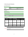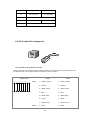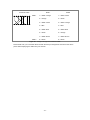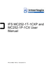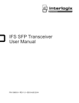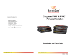
1
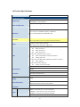
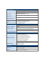
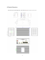
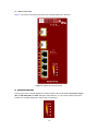
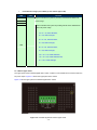
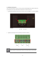
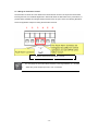
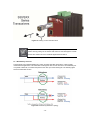
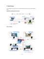
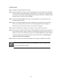
IFS MC352-4P-2S User Manual P/N 1072702 • REV A • ISS 22OCT13 Copyright Trademarks and patents Manufacturer © 2013 United Technologies Corporation Interlogix is part of UTC Climate Controls & Security, a unit of United Technologies Corporation. All rights reserved. The IFS MC352-4P-2S name and logo are trademarks of United Technologies. Other trade names used in this document may be trademarks or registered trademarks of the manufacturers or vendors of the respective products. Interlogix 3211 Progress Drive, Lincolnton, NC 28092 USA Authorized EU manufacturing representative: UTC Climate Controls & Security B.V., Kelvinstraat 7, 6003 DH Weert, Netherlands Intended use Use this product only for the purpose it was designed for; refer to the data sheet and user documentation for details. For the latest product information, contact your local supplier or visit us online at www.interlogix.com. Certification N4131 FCC compliance This equipment has been tested and found to comply with the limits for a Class A digital device, pursuant to part 15 of the FCC Rules. These limits are designed to provide reasonable protection against harmful interference when the equipment is operated in a commercial environment. This equipment generates, uses, and can radiate radio frequency energy and, if not installed and used in accordance with the instruction manual, may cause harmful interference to radio communications. You are cautioned that any changes or modifications not expressly approved by the party responsible for compliance could void the user's authority to operate the equipment. ACMA compliance Notice! This is a Class A product. In a domestic environment this product may cause radio interference in which case the user may be required to take adequate measures. Canada This Class A digital apparatus complies with Canadian ICES-003. Cet appareil numérique de la classe A est conforme á la norme NMB-003du Canada. European Union directives 2004/108/EC (EMC Directive): Hereby, UTC Climate Controls & Security Corporation, Inc. declares that this device is in compliance with the essential requirements and other relevant provisions of Directive 2004/108/EC. Contact Information For contact information, see www.interlogix.com or www.utcfssecurityproducts.eu. -2- TABLE OF CONTENTS 1. INTRODUCTION 4 1.1 PACKAGE CONTENTS ..........................................................................................................................4 1.2 HOW TO USE THIS MANUAL .................................................................................................................4 1.3 PRODUCT FEATURES ..........................................................................................................................5 1.4 PRODUCT SPECIFICATIONS ..................................................................................................................6 1.5 PHYSICAL DIMENSIONS .......................................................................................................................7 2. INSTALLATION 9 2.1 PRODUCT DESCRIPTION ......................................................................................................................9 2.1.2 Switch Front Panel.................................................................................................................. 10 2.1.3 LED Indicators ........................................................................................................................11 2.1.4 Switch Upper Panel ................................................................................................................12 2.1.5 Wiring the Power Inputs.......................................................................................................... 13 2.1.6 Wiring the Fault Alarm Contact ............................................................................................... 14 2.1.7 Cabling....................................................................................................................................15 2.1.7.1 Installing the SFP transceiver .............................................................................................. 15 2.1.7 Redundancy Overview............................................................................................................ 19 2.2 MOUNTING INSTALLATION ..................................................................................................................20 2.2.1 DIN-Rail mounting................................................................................................................... 20 2.2.2 Wall Mount Plate Mounting ..................................................................................................... 22 3. APPLICAITON 23 4. SWITCH OPERATION 25 4.1 ADDRESS TABLE ..............................................................................................................................25 4.2 LEARNING ........................................................................................................................................ 25 4.3 FORWARDING & FILTERING ................................................................................................................25 4.4 STORE-AND-FORWARD .....................................................................................................................25 4.5 AUTO-NEGOTIATION .........................................................................................................................26 5. TROUBLESHOOTING 27 6. CABLE CONNECTION PARAMETERS 28 APPENDIX A: NETWORKING CONNECTION 29 A.1 SWITCH’S RJ-45 PIN ASSIGNMENTS ..................................................................................................29 A.2 RJ-45 CABLE PIN ASSIGNMENTS .......................................................................................................30 -3- 1. Introduction Thank you for purchasing IFS Layer 2 Industrial Gigabit Switch with 4-Port 802.3at PoE+, The MC352-4P-2S descriptions of these models are as follows: MC352-4P-2S : Industrial 4-Port 10/100/1000T 802.3at PoE + 2-Port 100/1000X SFP Ethernet Switch (-40~75 Degree C) In the following section, the term “Industrial Gigabit PoE+ Switch” means the MC352-4P-2S. 1.1 Package Contents Open the box of the Industrial Gigabit PoE+ Switch and carefully unpack it. The box should contain the following items: ● Industrial Gigabit PoE+ Switch x 1 ● User's Manual x 1 ● DIN Rail Kit x 1 ● Wall Mount Kit x 1 If any of these are missing or damaged, please contact your dealer immediately; if possible, retain the carton including the original packing material, and use them again to repack the product in case there is a need to return it to us for repair. 1.2 How to Use This Manual This Industrial Gigabit PoE+ Switch User Manual is structured as follows: Chapter 2 Installation The chapter explains the feature, functionality and the physical installation of the Industrial Gigabit PoE+ Switch. Chapter 3 Application The chapter explains the Industrial Gigabit PoE+ Switch application. Chapter 4 Switch operation The chapter explains the Industrial Gigabit PoE+ Switch transmit operation. Chapter 5 Troubleshooting The chapter explains the troubleshooting of the Industrial Gigabit PoE+ Switch. Chapter 6 Cable Connection Parameters The chapter contains the cable connection parameters of the Industrial Gigabit PoE+ Switch. Appendix A This chapter contains cable information of the Industrial Gigabit PoE+ Switch. -4- 1.3 Product Features Physical Port MC352-4P-2S 4-Port 10/100/1000Base-T RJ-45 with IEEE 802.3af/802.3at PoE+ Injector 2 SFP interfaces, 100/1000Base-X dual mode (DIP switch control) Power over Ethernet Complies with IEEE 802.3af/IEEE 802.3at Power over Ethernet Plus End-Span PSE Up to 4 IEEE 802.3af/802.3at devices powered Supports PoE Power up to 30.8 watts for each PoE ports Provides DC 52V power over RJ-45 Ethernet cable to PD with Ethernet port Auto-detection of IEEE 802.3af/at equipment and protects devices from being damaged by incorrect installation Remote power feeding up to 100m Layer 2 Features Supports Auto-negotiation and 10/100Mbps half/full duplex and 1000Mbps full duplex mode Prevents packet loss with back pressure (Half-Duplex) and IEEE 802.3x PAUSE frame flow control (Full-Duplex) Automatic address learning and address aging Industrial Case/Installation IP30 aluminum metal case protection DIN Rail and Wall Mount Design 48V DC redundant power with polarity reverse protect function and connective removable terminal block for master and slave power Supports EFT protection 6000 VDC for power line Supports 6000 VDC Ethernet ESD protection -40 to 75 Degree C operating temperature Fiber Port Redundancy Dual SFP Ports Auto Link Redundant Mode Support Link status auto-detect and redundant on Dual ports with same connector type Only Primary-Port is active at a time, the Backup-Port is blocked While Primary-Port link fail occurrences, the traffic swaps to Backup-Port automatically Once the Primary-Port status backs to link up, the traffic swaps from Backup-Port to Primary-Port -5- 1.4 Product Specifications Model MC352-4P-2S Hardware Specification Copper Ports 4 x 10/100/1000Base-T RJ-45 TP Auto-MDI/MDI-X, Auto-negotiation 2 x SFP interfaces support 1000Base-SX/LX and 100Base-FX SFP transceivers SFP / mini-GBIC Slots DIP-1: SFP Port 5 1000Base-X (default) / 100Base-FX DIP-2: SFP Port 6 1000Base-X (default) / 100Base-FX DIP Switch Connector DIP-3 : Switch (default) / Fiber Redundant mode Terminal Block Pin 1 & 2 for Power 1; Pin 3 & 4 for alarm; Pin 5 & 6 for Power 2 Provides one relay output for power fail Alarm Alarm Relay current carry ability: 1A @ DC 24V 3x LED for System and Power: Green: DC Power 1 Green: DC Power 2 Green: Power Fault 2 x LED for Per Copper Port (Port-1~Port-4): LED Green: 1000 LNK/ACT, Orange:100 LNK/ACT Orange: PoE In-use 1 x LED for Per mini-GBIC interface (MC352-4P-2SPort-5 and Port-6): Green: LNK/ACT 4 x LED for PoE Power Usage (W) Orange: 30, 60, 90 and 120W ESD Protection 6KV DC EFT Protection 6KV DC Enclosure IP30 type metal case Installation DIN rail kit and wall mount ear Dimensions (W x D x H) 152 x 107 x 72 mm 1539g Weight Power Requirement Power Consumption/ 48V DC, 5A max. Redundant power with polarity reverse protection 135.1 watts / 451 BTU Dissipation Twisted-Pair 10Base-T: 2-Pair UTP CAT. 3,4,5, up to 100 meter 100Base-TX: 2-Pair UTP CAT. 5, 5e up to 100 meter Cable 1000Base-T: 4-Pair UTP CAT. 5e,6 up to 100 meter Fiber-Optic Cable -6- Switch Specification Switch Processing Scheme Store-and-Forward Address Table Flow Control Switch fabric Throughput 1K entries Back pressure for half duplex IEEE 802.3x Pause Frame for full duplex 12Gbps 8.93Mpps@64bytes (packet per second) Maximum Transmit Unit 9216 bytes TP: 10/20Mbps, 100/200Mbps, 2000Mbps Speed SX/LX: 2000Mbps (Full-duplex) FX: 200Mbps (Full-duplex) Power over Ethernet PoE Standard IEEE 802.3af/IEEE 802.3at Power over Ethernet/PSE PoE Power Supply Type End-Span PoE Power Output Per port 52V DC, 275mA. Max. 15.4 watts (IEEE 802.3af) Per port 52V DC, 535mA. Max. 30 watts (IEEE 802.3at) Power Pin Assignment 1/2(+), 3/6(-) Max. number of Class 4 PD 4 Standards Conformance IEEE 802.3 Ethernet/10Base-T IEEE 802.3u Fast Ethernet/100Base-TX IEEE 802.3ab Gigabit Ethernet/1000Base-T Standards Compliance IEEE 802.3z Gigabit Ethernet/1000Base-SX/LX IEEE 802.3x Full-Duplex Flow Control IEEE 802.3at Power over Ethernet Plus IEEE 802.3af Power over Ethernet Regulation Compliance FCC Part 15 Class A, CE IEC60068-2-32 (Free fall) Stability Testing IEC60068-2-27 (Shock) IEC60068-2-6 (Vibration) Environment Temperature Humidity Operating: -40~75 Degree C Storage: -40~75 Degree C Operating: 5~95% (Non-condensing) Storage: 5~95% (Non-condensing) -7- 1.5 Physical Dimensions MC352-4P-2S Industrial Gigabit PoE+ Switch dimensions (W x D x H): 161 x 107 x 72 mm -8- 2. Installation This section describes the functionalities of the Industrial Gigabit PoE+ Switch’s components and guides how to install it on the desktop. Basic knowledge of networking is assumed. Please read this chapter completely before continuing. 2.1 Product Description High Power PoE for Security and Public Service Applications To fulfill the demand of High Power PoE for network applications with Gigabit speed transmission under wide temperature, the MC352-4P-2S provide 4 10/100/1000Mbps ports featuring both IEEE 802.3af and IEEE 802.3at Power over Ethernet Plus (PoE+) that combine up to 30-watt power output and data per port over one Cat.5E / 6 Ethernet cable. With a total of up to 120 watts of PoE output capability, the MC352-4P-2S is designed specifically to satisfy the growing demand of higher power consuming network PDs (powered devices) such as PTZ (Pan, Tilt & Zoom) speed dome network cameras, multi-channel (802.11a / b / g / n) wireless LAN access points and other PoE network devices by providing double PoE power, rather than the current conventional 802.3af PoE. Environmentally Hardened Design The MC352-4P-2S is equipped with rugged IP30 metal case for easy deployment in heavy Industrial demanding environments. With IP30 metal case protection, the MC352-4P-2S provide a high level of immunity against electromagnetic interference and heavy electrical surges which are usually found on plant floors or in curb side traffic control cabinets. Being able to operate in the temperature range from -40 to 75 Degree C, the MC352-4P-2S can be placed in almost any difficult environment. The MC352-4P-2S allows either DIN rail or wall mounting for efficient use of cabinet space. Adjustable 6-Port Switch Mode or 4 + 2 Fiber Redundant Mode Via the built-in DIP switch, the MC352-4P-2S can be configured as 6-Port Ethernet switch or 4+2 fiber redundant mode. With the 6-port switch mode, the MC352-4P-2S can operate in Store-and-Forward mechanism with high performance; on the other hand, when in the 4+2 fiber redundant mode, it provides rapid fiber redundancy of link for highly critical Ethernet applications. The redundant-mode also supports auto-recovering function, if the destination port of a packet is link down, it will forward the packet to the other port of the backup pair. -9- 2.1.1 Switch Front Panel Figure 2-1 shows the front panels of MC352-4P-2S Industrial Gigabit PoE+ Switches. Figure 2-1: MC352-4P-2S Front Panels PoE Power Usage LED The front panel of the Industrial Gigabit PoE+ Switch has four LEDs which indicate “PoE Power Usages (W)” of 30W, 60W, 90W and 120W. With these LED indications, you can monitor current PoE power in use status of Industrial Gigabit PoE+ Switch easily and efficiently. - 10 - DIP Switch The front panel of the MC352-4P-2Sprovides one 3-DIP Switch which is for configuring 100 or 1000X fiber support and fiber redundant function. Refer to the table below to know about the 3-DIP switch settings and descriptions: For more information about the fiber redundancy function, please refer to the chapter 2.1.7 Redundancy Overview. OFF ON Fiber Redundant Switch Port 6 (DIP 2) 1000X 100FX Port 5 (DIP 1) 1000X 100FX Fiber Redundant (DIP 3) 2.1.3 LED Indicators System LED Color Function P1 P2 FAULT Green Green Green Light: indicates the power 1 has power. Light: indicates the power 2 has power. Light: indicates the either power 1 or power 2 has no power. 10/100/1000Base-T Interfaces LED Color Green LNK/ACT Orange PoE In-Use (Port 1~4) Orange Function Light: indicates the Switch is successfully connecting to the network at 1000Mbps. Blink: indicates that the Switch is actively sending or receiving data over that port. OFF: indicates that the Switch is inactively sending or receiving data over that port. Light: indicates the Switch is successfully connecting to the network at 10Mbps or 100Mbps. Blink: indicates that the Switch is actively sending or receiving data over that port. OFF: indicates that the Switch is inactively sending or receiving data over that port. Light: indicates the port is providing 52V DC in-line power. OFF: indicates the connected device is not a PoE Powered Device (PD). 100/1000Base-X SFP Interfaces (MC352-4P-2S) LED Color Function Light: indicates the Switch is successfully connecting to the network at 100/1000Mbps. LNK/ACT Green Blink: indicates that the Switch is actively sending or receiving data over that port. OFF: indicates that the Switch is inactively sending or receiving data over that port. - 11 - Per PoE Power Usage (Unit : Watts) (Lower LED to upper LED) LED Color Function 30 Lights to indicate the system is providing >30/60/90/120 Watts PoE 60 power usage. 90 Blinks to indicates the system is providing almost reach 30/60/90/120 Watts PoE power usage. 25 < X < 30, 30W LED flash; X >= 30, 30W LED light; 55 < X < 60, 60W LED flash; X >= 60, 60W LED light; 120 85 < X < 90, 90W LED flash; X >= 90, 90W LED light; 100 < X < 115, 120W LED flash; 115 < X < 120, 120W LED flash fast; X >= 120, 120W LED light. 2.1.4 Switch Upper Panel The upper panel of the Industrial Gigabit PoE+ Switch consists of one terminal block connector within two DC power inputs. Figure 2-2 shows the upper panel of the Switch. Figure 2-2 shows upper panel of Industrial Gigabit PoE+ Switch. Figure 2-2: Industrial Gigabit PoE Switch Upper Panel. - 12 - 2.1.4 Wiring the Power Inputs The 6-contact terminal block connector on the top panel of Industrial Gigabit PoE+ Switch is used for two DC redundant powers input. Please follow the steps below to insert the power wire. 1. Insert positive/negative DC power wires into contacts 1 and 2 for POWER 1, or 5 and 6 for POWER 2. V1- 2. V1 + V2 - V2 + Tighten the wire-clamp screws for preventing the wires from loosening. 1 2 Power 1 - 3 4 Fault + 5 6 Power 2 - + The wire gauge for the terminal block should be in the range between 12 and 24 AWG. - 13 - 2.1.5 Wiring the Fault Alarm Contact The fault alarm contacts are in the middle of the terminal block connector as the picture shows below. Inserting the wires, the Industrial Gigabit PoE+ Switch will detect the fault status of the power failure, or port link failure (available for managed model) and then forms an open circuit. The following illustration shows an application example for wiring the fault alarm contacts. 1 2 3 4 5 6 Insert the wires into the fault alarm contacts 1. 2. The wire gauge for the terminal block should be in the range between 12 ~ 24 AWG. Alarm relay circuit accepts up to 30V, max. 3A currents. - 14 - 2.1.6 Cabling 10/100/1000Base-T All 10/100/1000Base-T ports come with Auto-Negotiation capability. They automatically support 1000Base-T, 100Base-TX and 10Base-T networks. Users only need to plug a working network device into one of the 10/100/1000Base-T ports, and then turn on the Industrial Gigabit PoE+ Switch. The port will automatically runs in 10Mbps, 20Mbps, 100Mbps or 200Mbps and 1000Mbps or 2000Mbps after the negotiation with the connected device. 100Base-FX/1000Base-SX/LX The MC352-4P-2S Industrial Gigabit PoE+ Switch has two SFP interfaces that support 100/1000 dual speed mode (Optional Multi-mode/Single-mode 100Base-FX/1000Base-SX/LX SFP module) through DIP switch setting. Cabling Each 10/100/1000Base-T port uses RJ-45 sockets -- similar to phone jacks -- for connection of unshielded twisted-pair cable (UTP). The IEEE 802.3/802.3u/802.3ab Fast/Gigabit Ethernet standard requires Category 5 UTP for 100Mbps 100Base-TX. 10Base-T networks can use Cat.3, 4, 5 or 1000Base-T uses 5/5e/6 UTP (see table below). Maximum distance is 100 meters (328 feet). The 100Base-FX/1000Base-SX/LX SFP slot is used as LC connector with optional SFP module. Please see table below and know more about the cable’s specification. Port Type Cable Type Connector 10Base-T Cat 3, 4, 5, 2-pair RJ-45 100Base-TX Cat.5 UTP, 2-pair RJ-45 1000Base-T Cat.5/5e/6 UTP, 4-pair RJ-45 100Base-FX 1000Base-SX/LX 50/125µm or 62.5/125µm multi-mode 9/125µm single-mode 50/125µm or 62.5/125µm multi-mode 9/125µm single-mode LC (Multi/Single mode) LC (Multi/Single mode) Any Ethernet devices like hubs/PCs can be connected to the Industrial Gigabit PoE+ Switch by using straight-through wires. The four 10/100/1000Mbps ports are auto-MDI/MDI-X and can be used on straight-through or crossover cable. 2.1.6.1 Installing the SFP transceiver The sections describe how to insert an SFP transceiver into the MC352-4P-2S SFP slot. The SFP transceivers are hot-pluggable and hot-swappable. You can plug-in and out the transceiver to/from any SFP port without having to power down the Industrial Gigabit PoE+ Switch as the Figure 2-3 appears. - 15 - Figure 2-3: Plug-in the SFP transceiver Approved IFS SFP Transceivers IFS Industrial Gigabit PoE+ Switch supports both Single mode and Multi-mode SFP transceivers. The following list of approved IFS SFP transceivers is correct at the time of publication: Gigabit / Fast Ethernet Transceiver SFP for High Temperature: IFS Model SFP Description S35-2MLC SFP, LC Connector, Multi Mode, Gigabit, 2 fiber,850nm/850nm, 550m, Hardened -40~75°C S35-2SLC-10 SFP, LC Connector, Single Mode, Gigabit, 2 fiber,1310nm/1310nm, 10km, Hardened -40~75°C SFP, LC Connector, Single Mode, Gigabit, 2 fiber,1310nm/1310nm, 30km, S35-2SLC-30 Hardened -40~75°C SFP, LC Connector, Single Mode, Gigabit, 2 fiber,1550nm/1550nm, 70km, S35-2SLC-70 Hardened -40~75°C SFP, LC Connector, Single Mode, 10/100 Fast Ethernet, 1 fiber, S20-1SLC/A-20 1310nm/1550nm, 20km , A End SFP, LC Connector, Single Mode, 10/100 Fast Ethernet, 1 fiber, S20-1SLC/B-20 1310nm/1550nm, 20km , B End SFP, LC Connector, Multi Mode, 10/100 Fast Ethernet, 2 S20-2MLC-2 fiber,1310nm/1310nm, 2km SFP, LC Connector, Single Mode, 10/100 Fast Ethernet, 2 S20-2SLC-20 fiber,1310nm/1310nm, 20km SFP, LC Connector, Multi Mode, 10/100 Fast Ethernet, 2 S25-2MLC-2 fiber,1310nm/1310nm, 2km, Hardened -40~75°C SFP, LC Connector, Single Mode, 10/100 Fast Ethernet, 2 S25-2SLC-20 fiber,1310nm/1310nm, 20km, Hardened -40~75°C - 16 - IFS Model SFP Description S30-1SLC/A-10 SFP, LC Connector, Single Mode, Gigabit, 1 fiber, 1310nm/1550nm, 10km , A End S30-1SLC/A-20 SFP, LC Connector, Single Mode, Gigabit, 1 fiber, 1310nm/1550nm, 20km, A End S30-1SLC/A-60 SFP, LC Connector, Single Mode, Gigabit, 1 fiber, 1310nm/1550nm, 60km, A End S30-1SLC/B-10 SFP, LC Connector, Single Mode, Gigabit, 1 fiber, 1550nm/1310nm, 10km , B End S30-1SLC/B-20 SFP, LC Connector, Single Mode, Gigabit, 1 fiber, 1550nm/1310nm, 20km, B End S30-1SLC/B-60 SFP, LC Connector, Single Mode, Gigabit, 1 fiber, 1550nm/1310nm, 60km, B End S30-2MLC SFP, LC Connector, Multi Mode, Gigabit, 2 fiber,850nm/850nm, 550m S30-2MLC-2 SFP, LC Connector, Multi Mode, Gigabit, 2 fiber,1310nm/1310nm, 2km S30-2SLC-10 SFP, LC Connector, Single Mode, Gigabit, 2 fiber,1310nm/1310nm, 10km S30-2SLC-30 SFP, LC Connector, Single Mode, Gigabit, 2 fiber,1310nm/1310nm, 30km S30-2SLC-70 SFP, LC Connector, Single Mode, Gigabit, 2 fiber,1550nm/1550nm, 70km S30-RJ SFP, RJ-45, Gigabit, 100m 1000Base-SX/LX: Before connecting with switches, workstation or media converter, please do the following steps: 1. With 1000Base-X Fiber Speed, please set the DIP Switch of SFP Port 5 or Port 6 to the “OFF” position. OFF ON Port 6 (DIP 2) 1000X 100FX Port 5 (DIP 1) 1000X 100FX 2. Make sure both sides of the SFP transceivers are with the same media type, for example: 1000Base-SX to 1000Base-SX, 1000Base-LX to 1000Base-LX. 3. Check whether the fiber-optic cable type matches with the SFP transceiver model. To connect to 1000Base-SX SFP transceiver, use the Multi-mode fiber cable with one side being the male duplex LC connector type. To connect to 1000Base-LX SFP transceiver, use the Single-mode fiber cable with one side being the male duplex LC connector type. Connecting the fiber cable 1. Insert the duplex LC connector on the network cable into the SFP transceiver. 2. Connect the other end of the cable to a device – switches with SFP installed, fiber NIC on a workstation or a media converter. 3. Check the LNK/ACT LED of the SFP slot on the front of the Industrial Gigabit PoE+ Switch. Ensure that the SFP transceiver is operating correctly. - 17 - 100Base-FX: Before connecting with switches, workstation or media converter, please do the following steps: 1. With 100Base-FX Fiber Speed, please set the DIP Switch of SFP Port 5 or Port 6 to the “ON” position. OFF ON Port 6 (DIP 2) 1000X 100FX Port 5 (DIP 1) 1000X 100FX 2. Make sure both sides of the SFP transceivers are with the same media type or WDM pair, for example, 100Base-FX to 100Base-FX, 100Base-BX20-U to 100Base-BX20-D. 3. Check whether the fiber-optic cable type matches with the SFP transceiver model. To connect to SFP transceiver, use the multi-mode fiber cable with one side being the male duplex LC connector type. To connect to a SFP transceiver, use the single-mode fiber cable with one side being the male duplex LC connector type. Connecting the fiber cable 1. Insert the duplex LC connector on the network cable into the SFP transceiver. 2. Connect the other end of the cable to a device – switches with SFP installed, to fiber NIC on a workstation or a media converter. 3. Check the LNK/ACT LED of the SFP slot of the switch / converter. Ensure that the SFP transceiver is operating correctly. 2.1.6.2 Remove the Transceiver Module 1. Make sure there is no network activity by consulting or checking with the network administrator. Or through the management interface of the switch/converter (if available) to disable the port in advance. 2. Remove the Fiber Optic Cable gently. 3. Turn the latch of the SFP module to a horizontal position. 4. Pull out the module gently through the latch. - 18 - Figure 2-4: Pulling out from the transceiver Never pull out the module without pulling the latch or the push bolts on the module. Directly pulling out the module with violence could damage the module and the SFP module slot of the Industrial Gigabit Ethernet Switch. 2.1.7 Redundancy Overview The MC352-4P-2S Industrial Gigabit PoE+ Switch provides rapid fiber redundancy of link for highly critical Ethernet applications. The redundant-mode supports auto-recover function. If the destination port of a packet is link down, it forwards the packet to the other port of the backup pair. The following figure shows the redundant function. Figure 2-5: Redundancy Behavior Topology - 19 - Link status auto detect and redundant on Dual ports with same connector type. Only Primary-Port is active at a time, the Backup-Port is blocked. When Primary-Port link failure occurs, the traffic swaps to Backup-Port automatically. Once the Primary-Port status is back to link up, the traffic will swap from Backup-Port to Primary-Port. 2.2 Mounting Installation This section describes how to install the Industrial Gigabit PoE+ Switch and make connections to it. Please read the following topics and perform the procedures in the order being presented. In the installation steps below, this Manual uses IGS-801 (IFS 8 Port Industrial Gigabit Switch) as the example. However, the steps for IFS Industrial Gigabit PoE+ Switch are similar. 2.2.1 DIN-Rail mounting The DIN-Rail is screwed on the Industrial Gigabit Ethernet Switch when out of factory. When needed to replace the wall mount application with the DIN-Rail application on Industrial Gigabit Ethernet Switch, please refer to the following figures to screw the DIN-Rail on the Industrial Gigabit Ethernet Switch. To hang the Industrial Gigabit Ethernet Switch, follow the steps below: Step 1: Screw the DIN-Rail on the Industrial Gigabit Ethernet Switch. - 20 - Step 2: Lightly insert the bottom of the switch into the track Step 3: Check if the DIN-Rail is tightly on the track. Step 4: Please refer to the following procedures to remove the Industrial Gigabit Ethernet Switch from the track. - 21 - Step 5: Lightly pull out the bottom of the switch for removing it from the track. 2.2.2 Wall Mount Plate Mounting To install the Industrial Gigabit Ethernet Switch on the wall, please follow the instructions described below. Step 1: To remove the DIN-Rail from the Industrial Gigabit Ethernet Switch, loose the screws to remove the DIN-Rail. Step 2: Place the wall mount plate on the rear panel of the Industrial Gigabit Ethernet Switch. Step 3: Use the screws to screw the wall mount plate on the Industrial Gigabit Ethernet Switch. Step 4: Use the hook holes at the corners of the wall mount plate to hang the Industrial Gigabit Ethernet Switch on the wall. Step 5: To remove the wall mount plate, reverse the steps above. - 22 - 3. Applications In this paragraph, we will describe how to install Industrial Gigabit PoE+ Switch and the installation points. Industrial Operating Environment Harsh Climate - 23 - Installation Steps Step 1: Unpack the Industrial Gigabit PoE+ Switch. Step 2: Check the DIN-Rail is screwed on the Industrial Gigabit PoE+ Switch. (Please refer to DIN-Rail Mounting section for DIN-Rail installation, if the DIN-Rail is not screwed on the Industrial switch). If you want to wall-mount the Industrial Gigabit Ethernet Switch, please refer to Wall Mount Plate Mounting section for wall-mount plate installation. Step 3: To hang the Industrial Gigabit PoE+ Switch on the DIN-Rail track or wall, please refer to the Mounting Installation section. Step 4: Power on the Industrial Gigabit PoE+ Switch. (Please refer to the Wiring of the Power Inputs section for power input) The power LED on the Industrial Gigabit PoE+ Switch will light up. Please refer to the LED Indicators section for the functions of LED lights. Step 5: Prepare the twisted-pair, straight through Category 5 cable for Ethernet connection. Step 6: Insert one side of Category 5 cable into the Industrial Gigabit PoE+ Switch Ethernet port (RJ-45 port) and the other side of category 5 cable to the network devices' Ethernet port (RJ-45 port), eg. switch, PC or Server. The UTP port (RJ-45) LED on the Industrial Gigabit PoE+ Switch will light up when the cable is connected with the network device. Please refer to the LED Indicators section for the functions of LED lights. Step 7: When all connections are set and all LED lights show normally, the installation is complete. Be sure the connected network devices support MDI/MDI-X. If it does not support, then use the crossover category 5 Cable. - 24 - 4. Switch Operation 4.1 Address Table The Industrial Gigabit PoE+ Switch is implemented with an address table. This address table is composed of many entries. Each entry is used to store the address information of some nodes in network, including MAC address, port no, etc. This information comes from the learning process of Industrial Gigabit PoE+ Switch. 4.2 Learning When one packet comes from any port, the Industrial Gigabit PoE+ Switch will record the source address, port number and the other related information in address table. This information will be used to decide either forwarding or filtering for future packets. 4.3 Forwarding & Filtering When one packet comes from some ports of the Industrial Gigabit PoE+ Switch, it will also check the destination address besides the source address learning. The Industrial Gigabit PoE+ Switch will look up the address table for the destination address. If not found, this packet will be forwarded to all the other ports except the port which this packet comes in. And these ports will transmit this packet to the network it connected. If found, and the destination address is located at a different port from this packet that comes in, the Industrial Gigabit PoE+ Switch will forward this packet to the port where this destination address is located according to the information from address table. But, if the destination address is located at the same port with this packet that comes in, then this packet will be filtered; thereby increasing the network throughput and availability. 4.4 Store-and-Forward Store-and-Forward is one type of packet-forwarding techniques. A Store-and Forward Industrial Gigabit PoE+ Switch stores the incoming frame in an internal buffer and does the complete error checking before transmission. Therefore, no error packets occur. It is the best choice when a network needs efficiency and stability. The Industrial Gigabit PoE+ Switch scans the destination address from the packet-header, searches the routing table provided for the incoming port and forwards the packet, only if required. The fast forwarding makes the switch attractive for connecting servers directly to the network, thereby increasing throughput and availability. However, the switch is most commonly used to segment existing hubs, which nearly always improves the overall performances. An Ethernet Switching can be easily configured in any Ethernet network environment to significantly boost bandwidth using the conventional cabling and adapters. Due to the learning function of the Industrial Gigabit PoE+ Switch, the source address and corresponding port number of each incoming and outgoing packet are stored in a routing table. This information is subsequently used to filter packets whose destination address is on the same segment as the source address. This confines network traffic to its respective domain and reduces the overall load on the network. - 25 - The Industrial Gigabit PoE+ Switch performs "Store and Forward"; therefore, no error packets occur. More reliably, it reduces the re-transmission rate. No packet loss will occur. 4.5 Auto-Negotiation The STP ports on the Industrial Gigabit PoE+ Switch have built-in “Auto-negotiation”. This technology automatically sets the best possible bandwidth when a connection is established with another network device (usually at Power On or Reset). This is done by detecting the modes and speeds at the second of both devices that are connected and capable of. Both 10Base-T and 100Base-TX devices can connect with the port in either Half- or Full-Duplex mode. 1000Base-T can be only connected in Full-duplex mode. - 26 - 5. Troubleshooting This chapter contains information to help you solve issues. If the Industrial Gigabit PoE+ Switch is not functioning properly, make sure the Industrial Gigabit PoE+ Switch was set up according to instructions in this manual. The Link LED does not light up Solution: Check the cable connection and also try to swap one new cable. Performance is bad Solution: Check the speed duplex mode of the partner device. The Industrial Gigabit PoE+ Switch is run at Auto-negotiation mode and if the partner is set to half duplex, then the performance will be poor. 1000Base-T port link LED lights up, but the traffic is irregular Solution: Check that the attached device is not set to full duplex. Some devices use a physical or software switch to change duplex modes. Auto-negotiation may not recognize this type of full-duplex setting. Why the Industrial Gigabit PoE+ Switch doesn’t connect to the network Solution: Check per port LED on the Industrial Gigabit PoE+ Switch. Try another port on the Industrial Gigabit PoE+ Switch. Make sure the cable is installed properly. Make sure the cable is the right type. Turn off the power. After a while, turn on the power again. Why after my PoE PD device is connected to MC352-4P-2S, it cannot power on? Solution: 1. Please check the cable type of the connection from MC352-4P-2S (port 1 to port 4) to the other end. The cable should be an 8-wire UTP, Category 5 or above, EIA568 cable within 100 meters. A cable with only 4-wire, short loop or over 100 meters, all will affect the power supply. 2. Please check and assure the device is fully complied with IEEE 802.3af/IEEE 802.3at standard. Can I install S30-SXX or other non wide temperature SFP module into SFP slot of Industrial Gigabit PoE+ Switch? Solution: Yes, you can. However, since the S30-SXX and other non wide temperature SFP modules cannot operate under -40 Degree C, it must be brought to attention. Please pay attention to this point. - 27 - 6. Cable Connection Parameters The wiring details are as below: ■ 100FX Fiber Optical Cables: Standard Fiber Type Cable Specification 100Base-FX Multi-mode 50/125μm or 62.5/125μm (1310nm) Single-mode 9/125μm 100Base-BX-U Single-mode 9/125μm (TX :1310/RX :1550nm) 100Base-BX-D (TX :1550/RX :1310nm) 1000X Fiber Optical Cables: Standard Fiber Type Cable Specification 1000Base-SX (850nm) Multi-mode 50/125μm or 62.5/125μm 1000Base-LX (1310nm) Multi-mode 50/125μm or 62.5/125μm Single-mode 9/125μm Wiring Distances: Standard 1000Base-SX 1000Base-LX 1000Base-ZX Modal Bandwidth Max. Distance (MHz * km) (meters) 62.5 100 220 62.5 200 275 50 400 500 50 500 550 62.5 5 50 4 50 5 Single-mode 9 N/A 5000 Single-mode 9 N/A ~70,000 Fiber Multi-mode Multi-mode Diameter (micron) 550 The Single-mode port (1000Base-LX port) of MC352-4P-2S complies with LX 5 kilometers Notice: and provides additional margin allowing for 10/20/30/50/60 kilometers Gigabit Ethernet link on single mode fiber. - 28 - APPENDIX A: Networking Connection A.1 PoE RJ-45 Port Pin Assignments (End-Span) PIN NO RJ-45 POWER ASSIGNEMNT 1 ˙Power + 2 ˙Power + 3 ˙Power - 4 ˙Power - A.2 Switch’s RJ-45 Pin Assignments 1000Mbps, 1000Base-T Contact MDI MDI-X 1 BI_DA+ BI_DB+ 2 BI_DA- BI_DB- 3 BI_DB+ BI_DA+ 4 BI_DC+ BI_DD+ 5 BI_DC- BI_DD- 6 BI_DB- BI_DA- 7 BI_DD+ BI_DC+ 8 BI_DD- BI_DC- 10/100Mbps, 10/100Base-TX RJ-45 Connector pin assignment MDI MDI-X Contact Media Dependant Interface Media Dependant Interface -Cross 1 Tx + (transmit) Rx + (receive) - 29 - 2 Tx - (transmit) Rx - (receive) 3 Rx + (receive) Tx + (transmit) 4, 5 Not used 6 Rx - (receive) 7, 8 Tx - (transmit) Not used A.3 RJ-45 cable Pin Assignments The standard RJ-45 receptacle/connector There are 8 wires on a standard UTP/STP cable and each wire is color-coded. The following shows the pin allocation and color of straight cable, and crossover cable connection: Straight Cable 1 1 2 2 3 3 4 4 5 5 6 6 7 7 SIDE 1 8 SIDE 1 8 SIDE 2 SIDE2 1 = White / Orange 1 = White / Orange 2 = Orange 2 = Orange 3 = White / Green 3 = White / Green 4 = Blue 4 = Blue 5 = White / Blue 5 = White / Blue 6 = Green 6 = Green 7 = White / Brown 7 = White / Brown 8 = Brown 8 = Brown - 30 - Crossover Cable 1 1 2 2 3 3 4 4 5 5 6 6 7 7 SIDE 1 8 SIDE 1 8 SIDE 2 SIDE2 1 = White / Orange 1 = White / Green 2 = Orange 2 = Green 3 = White / Green 3 = White / Orange 4 = Blue 4 = Blue 5 = White / Blue 5 = White / Blue 6 = Green 6 = Orange 7 = White / Brown 7 = White / Brown 8 = Brown 8 = Brown Figure A-1: Straight-Through and Crossover Cable Please make sure your connected cables are with the same pin assignment and color as the above picture before deploying the cables into your network. - 31 -