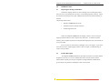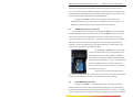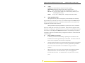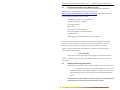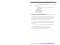
1
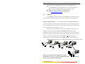
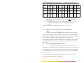
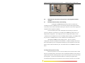
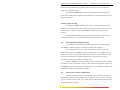
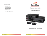
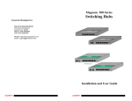
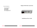
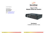
Magnum ITS Blade Corporate Headquarters GarrettCom, Inc. Ethernet Switch for 2070 Traffic Controller Chassis 47823 Westinghouse Dr. Fremont, CA 94539 Phone: 510.438.9071 Fax: 510-438-9072 Web: www.GarrettCom.com Email: [email protected] Installation and User Guide www . GarrettCom . com www . GarrettCom . com Magnum ITS Blade Hardened Switches for 2070’s Installation and User Guide (02/03) Magnum™ ITS Blade Ethernet Switch for Model 2070 Traffic Controller Chassis Installation and User Guide Part #: 84-00133, (Rev A 02/03) Trademarks Ethernet is a trademark of Xerox Corporation NEBS is a trademark of Telcordia Technologies UL is a registered trademark of Underwriters Laboratories GarrettCom, Magnum, Personal Hub and Personal Switch are trademarks of GarrettCom, Inc. Important: The Magnum ITS Blade Switches for Model 2070 Traffic Controllers contain no user serviceable parts. Attempted service by unauthorized personnel shall render all warranties null and void. If problems are experienced with Magnum ITS Blade Ethernet “2070” Switch products, consult Section 5, Troubleshooting, of this User Guide. Copyright © 2003 GarrettCom, Inc. All rights reserved. No part of this publication may be reproduced without prior written permission from GarrettCom, Inc. Printed in the United States of America. www . GarrettCom . com i Magnum ITS Blade Hardened Switches for 2070’s Installation and User Guide (02/03) Contacting GarrettCom, Inc Please use the mailing address, phone and fax numbers and email address listed below: GarrettCom, Inc. 47823 Westinghouse Dr. Fremont, CA 94539 Phone (510) 438-9071 Fax (510) 438-9072 Website: http://www.GarrettCom.com Email: [email protected] Federal Communications Commission Radio Frequency Interference Statement This equipment generates, uses and can radiate frequency energy and if not installed and used properly, that is in strict accordance with the manufacturer's instructions, may cause interference to radio communication. It has been tested and found to comply with the limits for a Class A computing device in accordance with the specifications in Subpart J of Part 15 of FCC rules, which are designed to provide reasonable protection against such interference when operated in a commercial environment. Operation of this equipment in a residential area is likely to cause interference, in which case the user at his/her own expense will be required to take whatever measures may be required to correct the interference. www . GarrettCom . com ii Magnum ITS Blade Hardened Switches for 2070’s Installation and User Guide (02/03) MAGNUM ETHERNET CONNECTIVITY PRODUCTS "DESIGNED AND MANUFACTURED IN THE USA" Overview GarrettCom, Inc. offers the Magnum line of Ethernet LAN connectivity products with industry-standard functionality. Magnum products are heavy duty, feature fiber-built-in ports, and have AC and DC power options to make them suitable for a variety of Industrial and Carrier Class applications. 6K25 Managed Fiber Switches, Gigabit, 100 and 10 Mbps, fiber and copper ports, mix-and match. Features SFF fiber for up to 25 fiber ports in a 1U unit. Configurable. 4K-Series Switches, 100 and 10 Mbps copper ports with optional 100Mb fiber ports, regular and Reverse rack-mount models, AC and DC power options, heavy duty specs. Quad-Series Fiber Switches, 100 & 10Mbps, fiber and copper ports, mixed-speed and mixed-media types, full switching performance, AC and DC power options. P62-Series “Outdoor” Ethernet Switches, for temperature uncontrolled applications, 6 10/100 and 2 100Mb fiber ports, managed and unmanaged models, all fiber types. Mixed-Media Fiber Hub, 16-port Stackable, 10/100 auto-sensing, AC and DC power Dual Speed 8-port and 16-port Stackable, 10/100 auto-sensing. AC and DC power cPCI Blade 12-port 10/100 “hub-on-a-card” for Compact PCI chassis rear I/O ITS Blade 8-port 10/100 “switch-on-a-card” for Model 2070 Traffic Controllers Stackable Hubs, SNMP Optional 10Mb series and 100Mb series, both w/ optional port modules, AC and DC power Personal Switches, 10/100Mb 8 port dual speed, Auto-negotiable with fiber option Personal Hubs, 100Mb or 10/100Mb 8-port, with two switched ports (1 fiber built in) Personal Hubs, 10Mb series 8-port + AUI, stackable to 5 high, + optional BNC of fiber port 8 or 9-port and 4 or 5-Port Personal Hubs, w/ man. up-link sw. Media Converters, 10Mb and 100Mb series, for offices and Hardened models for industrial applications. All media combinations, incl. fiber ST, SC, mm., single mode The “X-line” of configurable MiXed Media products: Stackable Concentrators, SNMP optional, 13-Ports Repeater Port Modules (RPMs), 6 types for Ethernet media Bridge Port Modules (BPMs), 4 types, for segment isolation Transceivers, 10Mb series Mini-Transceivers and Coax Models www . GarrettCom . com iii Feb, 03 Magnum ITS Blade Hardened Switches Installation and User Guide (02/03) TABLE OF CONTENTS PAGE 1.0 SPECIFICATIONS ................................................................................ 2 1.1 Technical Specifications....................................................................... 2 1.2 Ordering Information ........................................................................... 4 2.0 INTRODUCTION.................................................................................. 5 2.1 Inspecting the Package and Product..................................................... 5 2.2 Product Description.............................................................................. 5 2.3 100Mb Fiber ports, SC Connectors..................................................... 7 2.4 Frame Buffering and Latency............................................................... 7 2.5 Features and Benefits ........................................................................... 9 2.6 Applications ....................................................................................... 10 3.0 INSTALLATION ................................................................................. 11 3.1 Locating Magnum ITS Blade, 10/100Mb Hardened Switch.............. 11 3.2 Connecting Ethernet Media................................................................ 11 3.2.1 Connecting Twisted Pair (RJ-45, CAT 3 or CAT 5,)................ 11 3.2.2 Connecting Fiber Optic SC-type, "Snap-In" .............................. 12 3.2.3 Connecting Fiber Optic ST-type, “Snap-In” (Optional)............. 13 3.2.4 Connecting Single-Mode Fiber Optic ........................................ 13 3.2.5 Power Budget Calculations for ITS Blade Fiber Media............. 13 3.2.6 Connections to NIC’s to support Auto -Negotiation, RJ-45 ...... 14 3.3 Powering the Magnum ITS Blade Switches....................................... 14 4.0 OPERATION........................................................................................ 15 4.1 Dual-Speed Functionality, and Switching.......................................... 15 4.2 Auto-negotiation and Speed-sensing.................................................. 16 4.3 Auto-crossover feature on RJ-45 ports............................................... 16 4.4 LED’s ............................................................................................... 17 5.0 TROUBLESHOOTING....................................................................... 17 5.1 Before Calling for Assistance............................................................. 17 5.2 When Calling for Assistance.............................................................. 18 5.3 Return Material Authorization (RMA) Procedure.............................. 19 5.4 Shipping and Packaging Information ................................................. 19 APPENDIX A: WARRANTY INFORMATION ......................................... 20 REV A 11/02: This revision is the initial release of the ITS Blade Hardened Switches for Model 2070 Traffic Controller Chassis user manual. www . GarrettCom . com 1 Magnum ITS Blade Hardened Switches for 2070’s 1.0 SPECIFICATIONS 1.1 Technical Specifications Installation and User Guide (02/03) Ports Performance Fiber, ports #1 and # 8, full duplex at 100Mbps Copper (RJ-45) ports 2-7: auto-negotiating 10/100 Mbps, MDI / MDIX auto-crossover is automatically handled Network Standards IEEE 802.1p QoS prioritization, 802.3u, 802.3x flow control 100Mb: Ethernet IEEE 802.3 100BASE-TX, 100BASE-FX 10 Mb: Ethernet IEEE 802.3, 10BASE-T Packet-Processing Filtering and Forwarding Rate from 100Mbps ports: 148,800 pps max Filtering and Forwarding Rate from 10 Mbps ports: 14,880 pps max. Processing type: Store and Forward, all ports non-blocking Auto-learning: 4K-address table, shared for all ports Packet buffers: 256 KB, dynamically shared Latency (not including packet time): 100 to 10 Mbps: 5µs 10 to 100Mbps: 15µs Path Delay Value: 50 BT on all ports Maximum Ethernet Segment (or Domain) Lengths 10BASE-T (Unshielded twisted pair) 100BASE-TX (CAT 5 UTP) - 100 m (328 ft) - 100 m (328 ft) 100BASE-FX, full duplex: (multi-mode) 100BASE-FX, full duplex: (single-mode) 100BASE-FX, full duplex: (single-mode, long) - 2.0 km (6,562 ft) - 20.0 km (65,620 ft) - 40.0 km (131,240 ft) Operating Environment Ambient Temperature: 40°F to 167°F (-40°C to 75°C) cold start down to 25°C Storage Temperature: -40° to 185°F (-40°C to 85°C) Ambient Relative Humidity: 5% to 95% (non-condensing) Conformal coating applied as standard for humidity protection Altitude: -200 to 15,000 ft. (-60 to 5,000m) Operating Shock and Vibration: Designed to exceed CalTrans and ATC requirements and Telcordia GR-63-CORE Sections 4.3.1 and 4.4.3 Power Supply (Internal) 24VDC and -48VDC Power Supply Power Input Voltage: 5VDC at 1.9Amps, 2070 backplane pins ABC29 per TEES 03/02 Power Consumption: 8 watts typical, 10 watts maxm. www . GarrettCom . com 2 Magnum ITS Blade Hardened Switches for 2070’s Installation and User Guide (02/03) Model 2070 Chassis Standards Fits into slot A1 or A2, draws power from the Model 2070 chassis power supply. Note- the ITS Blade is stand-alone for Ethernet operations; it does not plug into any backplane signal pins Network Cable Connectors -6 RJ-45 shielded female ports and 2-fiber port 100Mbps: Category 5 UTP/STP, fiber (50/125, 62.5/125 mm, or single-mode at 9/125 micron) 10 Mbps: Category 3, 4, 5 UTP (Note: auto-sensing does not sense cable type) Mechanical Dimensions: 8.70 in D x 1.6 in W x 7.0 in H (220 mm x 40.4 mm x 177 mm) Weight: 0.5 lb. (0.25 kg.) LED Indicators PWR: Steady ON when power applied SPEED: (when LINK is ON): ON = 100Mbps; OFF = 10 Mbps LINK/ACT: Steady ON for LINK with no traffic, blinking indicates port is transmitting / receiving. F/H (RJ-45 ports only): ON = full-duplex, OFF = half-duplex MTBF (Bellcore method) Over 25 years MTBF @ 60°C. Email [email protected] for details Agency Approvals Emissions: meets FCC Part 15, Class A Designed to meet TS-2 specifications Warranty: Three years, return to factory www . GarrettCom . com 3 Made in USA Magnum ITS Blade Hardened Switches for 2070’s 1.2 Installation and User Guide (02/03) Ordering Information Magnum ITS Blade, 10/100 Ethernet Switch with two 100Mb Fiber Port TC62F-2MSC: Board-level Ethernet Switch for Model 2070 with six 10/100 RJ- 45 and two 100Mb FDX fiber multi-mode SC-type ports. HAVE 4K address table and 256KB packet buffers. For use in slot A1 or A2 of standard 2070 Controller chassis, which supplies power to Blade. Ethernet cable connections are from the rear of the 2070 chassis. Operates at -40°c to +75°C ambient temperature. TC62F-1M1SSC: Same as TC62F-2MSC, except one 100Mb Ethernet fiber port is 20km single-mode SC. TC62F-2SSC: Same as TC62F-2MSC, except both 100Mb Ethernet fiber port is 20km single-mode SC. TC62F-NOF: Same as TC62F-2MSC, except no fiber ports (Has six 10/100 Ethernet ports only. TC62F-PS-TEST: Power supply for ITS Blade bench tests. Universal AC input, mating TC62F DC jack plug. Magnum ITS models with other fiber connector types and combinations available, request quote for additional information. . GarrettCom, Inc. reserves the right to change specifications, performance characteristics and / or model offerings without notice. www . GarrettCom . com 4 Magnum ITS Blade Hardened Switches for 2070’s 2.0 INTRODUCTION 2.1 Inspecting the Package and Product Installation and User Guide (02/03) Examine the shipping container for obvious damage prior to installing this product; notify the carrier of any damage that you believe occurred during shipment or delivery. Inspect the contents of this package for any signs of damage and ensure that the items listed below are included. This package should contain: 1 Magnum ITS Blade Ethernet Switch 1 Installation and User Guide (this manual) 1 Product Registration Card Remove the Magnum ITS Blade from the shipping container. Be sure to keep the shipping container should you need to ship the unit at a later date. To validate the product warranty, please complete and return the enclosed Product Registration Card to GarrettCom, Inc. as soon as possible. In the event there are items missing or damaged, contact your supplier. If you need to return the unit, use the original shipping container. Refer to Chapter 5, Troubleshooting, for specific return procedures. 2.2 Product Description The Magnum ITS Blade is Hardened 8-port Ethernet Switch in a board-level module designed to fit into slot A1 or A2 of a standard 2070 Traffic Controller chassis. It allows Ethernet media to quickly and easily be configured as the high bandwidth communications protocol for the new generation of Intelligent Traffic Control systems. www . GarrettCom . com 5 Magnum ITS Blade Hardened Switches for 2070’s Installation and User Guide (02/03) The Magnum ITS Blade Ethernet Switch, equipped with six 10/100 RJ-45 ports and two 100Mb Fiber ports, easily connects to local Ethernet devices at the intersection such as video cameras and the Model 2070 Controller, while two Ethernet 100Mb fiber optic ports connect upstream to the TOC or to intermediate Ethernet switches in the traffic control network. The Magnum ITS Blade, entirely contained in a standard 2070 Traffic Control Chassis, draws its power from the 2070 chassis power supply. Noo 2070 chassis backplane signal pins are used The ITS Blade module easily can be fitted into either a new or existing 2070 chassis without creating any conflict with other installed modules. The Magnum ITS Blade specifications comply with Caltrans and NEMA TS-2-1998 Standards for Traffic Controller Assemblies. The two “future-proof” fiber ports have been designed as full-duplex 100Mbps switched fiber ports. Six copper (RJ-45) with full / half-duplex-10/100-auto-negotiating ports are included. The Magnum ITS Blade Hardened Switches provide the switching speed and the reliability to smoothly support streaming Ethernet traffic at 100Mbps or 10Mbps speed. The optional fiber ports are normally configured and tested with the ITS Blade in the factory, and are available in multi-mode and single-mode SC-type fiber connectors. Designed specifically to operate in Model 2070 Traffic chassis in temperature uncontrolled road side boxes, the Magnum ITS Blade can easily sustain the heat…. and the cold. Armored with unique thermal techniques (patent pending) developed by GarrettCom technologists extend the ambient temperature operating range beyond standard product ratings, www . GarrettCom . com 6 Magnum ITS Blade Hardened Switches for 2070’s Installation and User Guide (02/03) and improve operating lifetime and reliability. Ambient temperatures can be from -40°C to +75°C. The extreme temperature Ethernet technology is derived from the proven design of the companion products, the Magnum P62 Switch family, already widely in use in Traffic Control Systems and other Outdoor Industrial Ethernet LAN applications. The Magnum ITS Blade is available in three different TC62F models to suit installations using multi-mode, single mode or combinations of these two connectors. All models are specially designed for high reliability and EMI noise immunity. 2.3 100Mb Fiber ports, SC Connectors The Fast Ethernet fiber switched ports on the Magnum ITS Blade operate at fixed 100Mb speed and full-duplex mode for the best performance. The ITS Blade’s fiber ports are factorybuilt as either a multi-mode or single-mode SC connectors. A yellow label on the fiber port connector will indicate if it is single-mode . . . otherwise it is a multi-mode port. The 100Mbps fiber ports are each a switched port and perform as a domain, providing a high bandwidth backbone connection and supporting long (up to 20km single-mode, or 40km special “longreach”) fiber cable distances for installation versatility. On each Magnum ITS Blade, there are three LED’s for each of the RJ-45 switched ports. The F/H indicates full duplex when ON; when it is OFF, operation is half-duplex. One (LK/ACT) is steady ON to indicate LINK, and blinking indicates the port is transmitting / receiving. The 10/100 LED is ON for 100Mbps and OFF for 10 Mbps (when LINK is made). For fiber ports, the LEDs are the same except no F/H (and 10Mb is not possible). A device must be connected to the other end of a port’s cable and a proper link (LK lit) must be made with the device at the other end of the cable in order for each LINK LED to provide a valid indication of operating conditions. 2.4 Frame Buffering and Latency The Magnum ITS Blade is a store-and-forward switch. Each frame (or packet) is loaded into the Switch’s memory and inspected before forwarding can occur. This technique ensures that all forwarded frames are of a valid length and have the correct CRC, i.e., are good packets. This eliminates the propagation of bad packets, enabling all of the available bandwidth www . GarrettCom . com 7 Magnum ITS Blade Hardened Switches for 2070’s Installation and User Guide (02/03) to be used for valid information. While other switching technologies such as "cut-through" or "express" impose minimal frame latency, they will also permit bad frames to propagate out to the Ethernet segments connected. The "cut-through" technique permits collision fragment frames, which are a result of late collisions, to be forwarded to add to the network traffic. Since there is no way to filter frames with a bad CRC (the entire frame must be present in order for CRC to be calculated), the result of indiscriminate cut-through forwarding is greater traffic congestion, especially at peak activity. Since collisions and bad packets are more likely when traffic is heavy, the result of store-and-forward operation is that more bandwidth is available for good packets when the traffic load is greatest. To minimize the possibility of dropping frames on congested ports, each Magnum ITS Blade Hardened Switch dynamically allocates buffer space from its memory pool, ensuring that heavily used ports receive very large buffer space for packet storage. (Many other switches have their packet buffer storage space divided evenly across all ports, resulting in a small, fixed number of packets to be stored per port. When the port buffer fills up, dropped packets result.) This dynamic buffer allocation provides the capability for the maximum resources of the Magnum ITS Blade to be applied to all traffic loads, even when the traffic activity is unbalanced across the ports. Since the traffic on an operating network is constantly varying in packet density per port and in aggregate density, the Magnum ITS Blade Hardened Switches are constantly adapting internally to provide maximum network performance with the least dropped packets. When the ITS Blade Hardened Switch detects that its free buffer queue space is low, the Switch sends industry standard (full-duplex only) PAUSE packets out to the devices sending packets to cause “flow control”. This tells the sending devices to temporarily stop sending traffic, which allows a traffic catch-up to occur without dropping packets. Then, normal packet buffering and processing resumes. This flow-control sequence occurs in a small fraction of a second and is transparent to an observer. See Section 4.6 for additional details. Another feature implemented in Magnum ITS Blade Hardened Switch is a collisionbased flow-control mechanism (when operating at half-duplex only). When the Switch detects that its free buffer queue space is low, the Switch prevents more frames from entering by forcing a collision signal on all receiving RJ-45 half-duplex ports in order to stop incoming traffic. The latency (the time the frame spends in the Switch before it is sent along or www . GarrettCom . com 8 Magnum ITS Blade Hardened Switches for 2070’s Installation and User Guide (02/03) forwarded to its destination) of the ITS Blade Ethernet Switch varies with the port-speed types, and the length of the frame is a variable here, as it is with all store-and-forward switches. For 10 Mb-to-10 Mb or 10 Mb-to-100Mb or 100Mb-to-10 Mb forwarding, the latency is 15 microseconds plus the packet time at 10Mb. For 100Mb-to-100Mb forwarding, the latency is 5 microseconds plus the packet time at 100Mb. 2.5 Features and Benefits 100Mb switching services for high performance Ethernet LANs Magnum ITS Blade provides Fast Ethernet switching on all ports. They perform high-speed filter/forward operations on the traffic, giving each port’s segment a full 100Mb (or possibly 10 Mb for RJ-45 ports) of bandwidth. IEEE 802.1P QoS prioritization supports data and streaming traffic Mixtures of bursty data packets and streaming packets for video are supported, with priority use of the bandwidth given to streaming for best quality video. Two “future-proof” fiber ports with SC connectors Built-in fiber ports may be ordered with 100Mb full-duplex multi-mode SC, single-mode SC, and (special order) SSCL-type connectors. The fiber ports are set to full-duplex mode. No Media Converters needed. All RJ-45 ports are auto-negotiating, and auto-crossover RJ-45 ports support twisted pair “copper” segment connections, with 10 or 100Mb speed and full / half-duplex mode selected by Ethernet standard IEEE 802.3u auto-negotiation. Auto-crossover is standard. Front-mounted LEDs for convenient viewing The LEDs that indicate operating status are on the top of the unit for easy viewing in any situation. As the units are vertically mounted in 2070 Box, Frontsurface viewing is convenient for the user to see the status. Installation is “Plug and Play”, operation is transparent to software The Magnum ITS Blade operates as a hardened switch, only forwarding those packets from each domain that are needed on the other domains. Internal address tables are self-learning, enabling users to change port connections or 10/100 domains without affecting operations. Thermal design techniques for use in temp. uncontrolled applications The ITS Blade’s advanced thermal techniques extend the ambient temperature operating range beyond standard product ratings, and improve operating lifetime and reliability. www . GarrettCom . com 9 Magnum ITS Blade Hardened Switches for 2070’s Installation and User Guide (02/03) ITS Blades are designed and advised to use only with 2070 Chassis The ITS Blade hardened switch is designed to use with 2070 backplane pins ABC29 per TEES 03/02 and draw the power from the chassis itself. MTBF over 25 years, per Bellcore calculation method Email [email protected] for MTBF details 2.6 Applications The ITS Blade is designed specifically for harsh temperature environments and brings future-proof fiber and widely used copper connectivity to out-of-the-way sites and outdoors. Example 1. Magnum ITS Blade In this example, a Magnum ITS Blade Hardened Switch serves real time roadside traffic data collection and transmits it to a remote control station over fiber. Since multiple traffic control sites here are a long distance apart, they are all connected in series to each other and to the central station or TOC. Some local users (using RJ-45 ports) may operate at 100Mbps, and some users and utility devices may run at 10 Mbps. A Magnum ITS Blade Hardened Switch serves this requirement economically and efficiently. The six full- and half-duplex switched ports make the required setup simple for collection of traffic data, including streaming video from one or more cameras. The advanced thermal techniques enable operation in un-controlled outdoor temperatures, and provide high reliability of the ITS Blade, make it suited to the roadside site. The two 100Mbps full-duplex fiber ports fulfill the long distance connection need, and provide Figure 2.6: A ITS Blade connects combinations of 10 Mbps and100Mbps network devices, providing a 100Mb Ethernet fiber for access to the central control station (TOC) www . GarrettCom . com 10 backbone Magnum ITS Blade Hardened Switches for 2070’s 3.0 Installation and User Guide (02/03) INSTALLATION This chapter provides instructions for installing Magnum ITS Blade units. 3.1 Locating Magnum ITS Blade, 10/100Mb Hardened Switch The location of a Magnum ITS Blade Hardened Switch is designed primarily for the specific application, such as road traffic data collection and control stations, the Magnum ITS Blade draws the power from 2070 chassis for high reliability and convenience in out-of-the way locations. Entirely contained in a standard 2070 Traffic controlled chassis, the ITS Blade easily deploy in temperature un-controlled roadside boxes, and can sustained the heat. …and the cold. The front mounted LEDs are easily viewable to see the data traffic and the port status. 3.2 Connecting Ethernet Media The Magnum ITS Blade Hardened Switches can be connected to the following three media types: 100BASE-TX, 10BASE-T and 100BASE-FX. CAT 5 cables should be used when making 100BASE-TX connections. When the ports are used as 10BASE-T ports, CAT 3 may be used. In either case, the maximum distance for unshielded twisted pair cabling is 100 meters (328 ft). For fiber port 100BASE-FX multi-mode, 50/125 or 62.5/125 microns cabling can be used, whereas for single-mode, 9/125 microns cabling should be used. Fiber cabling supports much longer cable distance and higher bandwidths as compared to copper wiring. Media Twisted Pair (CAT 3 or 5) Twisted Pair (CAT 5) Fiber (Multi-mode) Fiber (Single-mode) IEEE Standard 10BASE-T 100BASE-TX 100BASE-FX 100BASE-FX Connector RJ-45 RJ-45 SC SC NOTE: It is recommended that high quality CAT. 5 cables (which work for both 10 Mbps and 100Mbps) be used whenever possible in order to provide flexibility in a mixed-speed network, since P80-series switch ports are auto-sensing for either 10 and 100Mbps. Note that the auto-sensing function does not sense the cable type. 3.2.1 Connecting Twisted Pair (RJ-45, CAT 3 or CAT 5, Unshielded or Shielded) The following procedure describes how to connect a 10BASE-T or 100BASE-TX twisted pair segment to the RJ-45 port. The procedure is the same for both unshielded and shielded twisted pair cables. www . GarrettCom . com 11 Magnum ITS Blade Hardened Switches for 2070’s 1. Installation and User Guide (02/03) Using standard twisted pair media, insert either end of the cable with a RJ-45 plug into the RJ-45 connector of the port. Note that, even though the connector is shielded, either unshielded or shielded cables and wiring may be used. 2. Connect the other end of the cable to the corresponding device. 3. Use the LINK LED to ensure proper connectivity by noting that the LED will be illuminated when the unit is powered and proper connection is established. If this does not help, ensure that the cable is connected properly and that the device on the other end is powered and is not defective. 4. For Port # 1 or 1SW, if the LINK LED is not illuminated, move the switch, which has a crossover or up-link for linking to another hub or Switch. 3.2.2 Connecting Fiber Optic SC-type, "Snap-In" The following procedure applies to installations using SC-type fiber connectors. This procedure applies to ports using multi-mode SC fiber connectors. 1. Before connecting the fiber optic cable, remove the protective dust cap / plug from the end of the fiber connectors, exposing the ports opening. Save the dust cover / plug for future use in case the fiber cable needs to be unplugged for service. 2. Wipe clean the ends of the dual connectors with a soft cloth or lint-free lens tissue dampened in alcohol. Make certain the connectors are clean before connecting. Then, insert the square male connector into the SC female jack of the Fiber port connector until it clicks and secures. Note: One strand of the duplex fiber optic cable may be coded using color bands at regular intervals; you should use the color-coded strand on the associated ports at each end of the fiber optic cable segment. 3. Connect the Transmit (TX) port on the Magnum Fiber port to the Receive (RX) port of the remote device. Begin with the color-coded strand of the cable for this first TX-to-RX connection. Note – the two male square-end SC cable strands may be fastened together to plug as a unit. 4. Connect the Receive (RX) port to the Transmit (TX) port of the remote device. Use the non-color coded fiber strand for this. www . GarrettCom . com 12 Magnum ITS Blade Hardened Switches for 2070’s 5. Installation and User Guide (02/03) The LINK LED for the fiber connector will illuminate when a proper connection has been established at both ends (and when power is ON in the unit). If LINK is not lit after cable connection, the normal cause is improper cable polarity. Swap the fiber cables at the fiber connector to remedy this situation. 3.2.3 Connecting Fiber Optic ST-type, “Snap-In” (Optional) The following procedure applies to installations using ST-type fiber connectors, i.e., using multi-mode ST. When connecting fiber media to ST connectors, simply twist on the two round male connectors into the ST female jacks of the Fiber connector until it clicks and secures. 3.2.4 Connecting Single-Mode Fiber Optic When using single-mode fiber cable, be sure to use single-mode fiber port connectors. Single-mode fiber cable has a smaller diameter than multi-mode fiber cable (9/125 microns for single-mode, 50/125 or 62.5/125 microns for multi-mode where xx/xx are the diameters of the core and the core plus the cladding respectively). Single-mode fiber allows full bandwidth at longer distances, about 20Km with the single-mode SC. The same procedures as for multi-mode fiber apply to single-mode fiber connectors. Follow the steps listed in Section 3.2.2 above. 3.2.5 Power Budget Calculations for ITS Blade Fiber Media Receiver Sensitivity and Transmitter Power are the parameters necessary to compute the power budget. To calculate the power budget of different fiber media installations using Magnum products, the following equations should be used: OPB (Optical Power Budget) = PT(min) - PR(min) where PT = Transmitter Output Power, and PR = Receiver Sensitivity Worst case OPB = OPB - 1dB(for LED aging) - 1dB(for insertion loss) Worst case distance = {Worst case OPB, in dB} / [Cable Loss, in dB/Km] where the “Cable Loss” for 62.5/125 and 50/125µm (m.m.) is 2.8 dB/km, and the “Cable Loss” for 100/140 (Multi-mode) is 3.3 dB/km, and the “Cable Loss” for 9/125 (Single-mode) is 0.5 dB/km The following data has been collected from component manufacturer’s (HP’s and Siemens’) web sites and catalogs to provide guidance to network designers and installers. www . GarrettCom . com 13 Magnum ITS Blade Hardened Switches for 2070’s Installation and User Guide (02/03) Fiber Port Module Speed, TC62FxMSC 100Mb Multimode FX 2 (0.4) 1300 62.5/125 -20 50/125 -23.5 -31 -31 9.0 5.5 2.5 2.0 14 12 5 4 TC62F- 100Mb Singlemode FX 20 (0.4) 1300 9/125 -15 -31 14 28 17.5 35 100Mb Singlemode FX 40 (0.4) 1300 9/125 -5 -34 27 54 32.5 65 xSSC “Long Reach” Mode Std. Std. km Wave- Cable X’mitr R’cvr Worst Worst* fdx length Size Output Sens. OPB, distance (hdx) nm PT , dB PR ,dB dB Km, fdx µm typical typical* OPB, distance dB Km, fdx * Note: The use of either multi-mode or single-mode fiber to operate at 100Mbps speed over long distances (i.e., over approx. 400 meters) can be achieved only if the following factors are both applied: • The 100Mb fiber segment must operate in full-duplex (FDX) mode, and the worstcase OPB of the fiber link must be greater than the fiber cable’s passive Attenuation. (Attenuation = Cable loss + LED aging loss + Insertion loss + safety factor) 3.2.6 Connections to NIC’s to support Auto -Negotiation, RJ-45 ports The copper ports of Magnum ITS Blade Hardened Switches will function properly with NICs (Network Interface Cards) which support Auto-Negotiation, and the Fast Link Pulse (FLP) coding for the 100BASE-TX signaling system. When connecting a NIC to a ITS Blade, it may be necessary to reload the NIC drivers on the user device if the NIC has been communicating with a protocol other than 100BASE-TX (such as 10BASE-T). When 100Mb speed is agreed and in use, the 10/100 LED is steady ON. It is OFF if there is no traffic or if 10 Mbps traffic. 3.3 Powering the Magnum ITS Blade Switches The Magnum ITS Blade is powered up from the A1 or A2 backplane of a standard 2070 Traffic Controller chassis. The ITS Blade will draw about 1.9A from 5VDC at pin 29 of the backplane connector. The PWR led will turn GREEN as soon as the power is applied to the ITS Blade. Once received enough required power from the backplane, the ITS Blade will become operational. Power Input Voltage: 5VDC at 1.9Amps, 2070 backplane pins ABC29 per TEES 03/02 Power Consumption: 8 watts typical, 10 watts maxm. www . GarrettCom . com 14 Magnum ITS Blade Hardened Switches for 2070’s Installation and User Guide (02/03) Typical Model 2070 Chassis, rear view 4.0 OPERATION- the function and operation of the Magnum ITS Blade Switches. 4.1 Dual-Speed Functionality, and Switching The Magnum ITS Blade Hardened Switch provide six 10/100 RJ-45 switched ports, and two 100Mb fiber ports. The architecture supports a dual speed-switching environment, with two built-in full-duplex “future-proof” fiber ports. The six RJ-45 copper ports equipped with auto-negotiation capability. The switched RJ-45 ports are full / half duplex and auto-sensing for speed. (See section 2.2). When the connected device is 10 Mbps, the ITS Blade obeys all the rules of 10 Mbps Ethernet configurations. The 10 Mbps users share a 10 Mbps traffic domain, and can “communicate with” 100Mbps users as well as 100Mbps domain. Similarly, the 100Mbps traffic obeys the rules of 100Mbps Ethernet, and can communicate with 10Mb domain too. All Magnum ITS Blades are plug-and-play devices. There is no software configuration to be done at installation or for maintenance. The Half / full duplex mode for the RJ-45 switched RJ-45 ports is user dependent and changes (by auto-negotiation) to full or half duplex as the unit attached with these ports. The internal functions of ITS Blade are described below. Switching, Filtering and Forwarding Each time a packet arrives on one of the switched ports, the decision is taken to either filter or to forward the packet. Packets whose source and destination addresses on the same port segment will be filtered, constraining them to one port and relieving the rest of the network from processing them. A packet whose destination address is on another port segment will be forwarded to the appropriate port, and will not be sent to the other ports where it is not needed. www . GarrettCom . com 15 Magnum ITS Blade Hardened Switches for 2070’s Installation and User Guide (02/03) Packets needed for maintaining the operation of the network (such as occasional multi-cast packets) are forwarded to all ports. The Magnum ITS Blade Switch operate in the store-and-forward switching mode, which eliminates bad packets and enables peak performance to be achieved when there is heavy traffic on the network. Switching, Address Learning The Magnum ITS Blade has address table capacity of 16K node addresses, and are suitable for use in large networks. They are self-learning, so that as nodes are added or removed or moved from one segment to another, the ITS Blade automatically keeps up with node locations. An address-aging algorithm causes least-used addresses to fall out in favor of new frequently used addresses. To reset the address buffer, cycle power down-and-up. 4.2 Auto-negotiation and Speed-sensing All six RJ-45 ports independently support auto-negotiation for speed in 10BASE-T and 100BASE-TX modes. Operation is according to the IEEE 802.3u standard. When a RJ-45 cable connection is made, and each time a LINK is enabled, autonegotiation takes place. The ITS Blade advertises its capability for 10 or 100 Mbps speed, and the device at the other end of the cable should similarly advertise / respond and both sides will agree to the speed being used. Depending upon the device connected, this will result in agreement to operate at either 10 Mbps or 100Mbps speed. When the ‘LK/ACT’ LED is ON, steady ON indicates LINK with no traffic, blinking ON indicates the port is transmitting / receiving. The port has auto-negotiated for operation. (If a ITS Blade RJ-45port is connected to a non-negotiating device, it will default to 10 Mbps speed and half-duplex mode, per the IEEE 802.3u standard). 4.3 Auto-crossover feature on RJ-45 ports All six RJ-45 ports have the auto-crossover feature. MDI vs. MDIX connections are automatically sensed and correctly handled. There is no up-link switch on any port. Any RJ-45 port can be connected either to a NIC or to a switch / hub port using standard twisted pair cables. No crossover cables are required www . GarrettCom . com 16 Magnum ITS Blade Hardened Switches for 2070’s 4.4 Installation and User Guide (02/03) LED’s POWER: Illuminates GREEN, steady on when power applied. SELF-TEST: Indicates the self-test at power up was not successful. F/H: ON = Full Duplex and Link, OFF = Half Duplex and / or no Link. LK/ACT: Per port, steady ON for LINK with no traffic, blinking indicates port is transmitting and receiving. 10/100: Per port, ON = 100Mbps; OFF = 10 Mbps (when LINK is made). 5.0 TROUBLESHOOTING All Magnum Ethernet products are designed to provide reliability and consistently high performance in all network environments. The installation Magnum ITS Blade Hardened Switch is a straightforward procedure (see INSTALLATION, Section 3); the operation is also straightforward and is discussed in Section 4. Should problems develop during installation or operation, this section is intended to help locate, identify and correct these types of problems. Please follow the suggestions listed below prior to contacting your supplier. However, if you are unsure of the procedures described in this section or if the Magnum ITS Blade Hardened Switch is not performing as expected, do not attempt to repair the unit; instead contact your supplier for assistance or contact GarrettCom Customer Support. 5.1 Before Calling for Assistance 1. If difficulty is encountered when installing or operating the unit, refer back to the Installation Section of the applicable chapter of this manual. Also check to make sure that the various components of the network are interoperable. 2. Check the cables and connectors to ensure that they have been properly connected and the cables/wires have not been crimped or in some way impaired during installation. (About 90% of network downtime can be attributed to wiring and connector problems.) 3. Make sure that an AC power cord is properly attached to each Magnum ITS Blade Hardened Switch unit. Be certain that each AC power cord is plugged into a functioning electrical outlet. Use the PWR LEDs to verify each unit is receiving power. www . GarrettCom . com 17 Magnum ITS Blade Hardened Switches for 2070’s 4. Installation and User Guide (02/03) If the problem is isolated to a network device other than the Magnum ITS Blade Hardened Switch product, it is recommended that the problem device is replaced with a known good device. Verify whether or not the problem is corrected. If not, go to Step 5 below. If the problem is corrected, the Magnum ITS Blade Hardened Switch and its associated cables are functioning properly. 5. If the problem continues after completing Step 4 above, contact your supplier of the Magnum ITS Blade Hardened Switch unit or if unknown, contact GarrettCom, Inc. by fax, phone or email ([email protected]) for assistance. 5.2 When Calling for Assistance Please be prepared to provide the following information. 1. A complete description of the problem, including the following points: a. The nature and duration of the problem; b. Situations when the problem occurs; c. The components involved in the problem; d. Any particular application that, when used, appears to create the problem; 2. An accurate list of GarrettCom product model(s)involved, with serial number(s). Include the date(s) that you purchased the products from your supplier. 3. It is useful to include other network equipment models and related hardware, including personal computers, workstations, terminals and printers; plus, the various network media types being used. 4. A record of changes that have been made to your network configuration prior to the occurrence of the problem. Any changes to system administration procedures should all be noted in this record. www . GarrettCom . com 18 Magnum ITS Blade Hardened Switches for 2070’s 5.3 Installation and User Guide (02/03) Return Material Authorization (RMA) Procedure All returns for repair must be accompanied by a Return Material Authorization (RMA) number. To obtain an RMA number, please use this URL https://rma.garrettcom.com/rma/rma_request_noaccount.php to fill out the form. Please have the following information readily available: Name and phone number of your contact person. Name of your company / institution Your shipping address Product name Serial Number (or Invoice Number) Packing List Number (or Sales Order Number) Date of installation Failure symptoms, including a full description of the problem. GarrettCom will carefully test and evaluate all returned products, will repair products that are under warranty at no charge, and will return the warranty-repaired units to the sender with shipping charges prepaid (see Warranty Information, Appendix A, for complete details). However, if GarrettCom cannot duplicate the problem or condition causing the return, the unit will be returned as: No Problem Found. GarrettCom reserves the right to charge for the testing of non-defective units under warranty. Testing and repair of product that is not under warranty will result in a customer (user) charge. 5.4 Shipping and Packaging Information Should you need to ship the unit back to GarrettCom, please follow these instructions: 1. Package the unit carefully. It is recommended that you use the original container if available. Units should be wrapped in a "bubble-wrap" plastic sheet or bag for shipping protection. (You may retain all connectors and this Installation Guide.) CAUTION: Do not pack the unit in Styrofoam "popcorn" type packing material. This material may cause electro-static shock damage to the unit. www . GarrettCom . com 19 Magnum ITS Blade Hardened Switches for 2070’s 2. 3. 4. Installation and User Guide (02/03) Clearly mark the Return Material Authorization (RMA) number on the outside of the shipping container. GarrettCom is not responsible for your return shipping charges. Ship the package to: GarrettCom, Inc. 47823 Westinghouse Dr. Fremont, CA 94539 Attn.: Customer Service APPENDIX A: WARRANTY INFORMATION GarrettCom, Inc. warrants its products to be free from defects in materials and workmanship for a period of three (3) years from the date of shipment by GarrettCom. During this warranty period, GarrettCom will repair or, at its option, replace components in the products that prove to be defective at no charge other than shipping and handling, provided that the product is returned pre-paid to GarrettCom. This warranty will not be effective if, in the opinion of GarrettCom, GarrettCom has damaged by misuse, misapplication, or as a result of service or modification other than the product. GarrettCom reserves the right to make a charge for handling and inspecting any product returned for warranty repair which turns out not to be faulty. Please complete the warranty card as this acts as a product registration and mail it to GarrettCom within two weeks of your purchase. www . GarrettCom . com 20