1
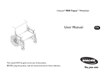
Invacare® 9000 Topaz™Wheelchair User Manual This manual MUST be given to the user of the product. BEFORE using this product, read this manual and save for future reference. EN © 2011 Invacare Corporation. All rights reserved. Republication, duplication or modification in whole or in part is prohibited without prior written permission from Invacare. Trademarks are identified by ™ and ®. All trademarks are owned by or licensed to Invacare Corporation or its subsidiaries unless otherwise noted. Invacare® 9000 Topaz™Wheelchair 2 Part No. 1150770 CONTENTS 1 GENERAL 2 Symbols .................................................................................................................................................................................................................................................... 5 OVERVIEW 6 3 Label Location......................................................................................................................................................................................................................................... 6 Component Identification .................................................................................................................................................................................................................... 7 Typical Product Parameters ................................................................................................................................................................................................................ 8 SAFETY 10 4 General Guidelines .............................................................................................................................................................................................................................. 10 Operating Information........................................................................................................................................................................................................................ 11 Safety/Handling of Wheelchairs........................................................................................................................................................................................................ 17 SAFETY INSPECTION/TROUBLESHOOTING 24 5 Safety Inspection Checklists .............................................................................................................................................................................................................. 24 Troubleshooting ...................................................................................................................................................................................27 Maintenance .......................................................................................................................................................................................................................................... 27 FRONT RIGGINGS 30 6 Installing/Removing Swingaway Footrest Assembly ..................................................................................................................................................................... 30 Swingaway Footrest Height Adjustment ........................................................................................................................................................................................ 31 Installing/Removing Elevating Legrest Assembly ........................................................................................................................................................................... 31 Adjusting Elevating Legrest Assembly ............................................................................................................................................................................................. 32 ARMS 35 7 Adjusting Armrest Height .................................................................................................................................................................................................................. 35 Replacing Desk/Full Length Armrest Pad ....................................................................................................................................................................................... 37 Removing or Replacing Armrest ...................................................................................................................................................................................................... 37 SEAT AND BACK 39 Part No. 1150770 5 3 Invacare®9000 Topaz™Wheelchair CONTENTS 8 Replacing Seat Upholstery ................................................................................................................................................................................................................. 39 Replacing Back Upholstery ................................................................................................................................................................................................................ 40 Adjusting Back Height......................................................................................................................................................................................................................... 41 Adjusting Seat Depth .......................................................................................................................................................................................................................... 42 Adjusting Seat Width .......................................................................................................................................................................................................................... 42 REAR WHEELS 43 9 Removing/Installing Rear Wheels..................................................................................................................................................................................................... 43 FRONT CASTERS 45 Installing/Replacing 15.24 x 20.32 cm (6 or 8 in) Front Casters and Forks ........................................................................................................................... 45 Front Caster Mounting Adjustments .............................................................................................................................................................................................. 46 10 ANTI-TIPPERS/WHEEL LOCKS 47 Installing Anti-Tippers ......................................................................................................................................................................................................................... 47 Using/Adjusting Wheel Locks ........................................................................................................................................................................................................... 49 11 OPTIONS 52 Installing Crutch and Cane Carrier.................................................................................................................................................................................................. 52 Installing Seat Positioning Strap ........................................................................................................................................................................................................ 53 Wheel Lock Extension Handle ......................................................................................................................................................................................................... 54 Installing/Removing Solid Seat Insert ............................................................................................................................................................................................... 55 Installing/Removing Solid Back Insert .............................................................................................................................................................................................. 56 Installing O2 Holder/Telescoping I.V. Rod with O2 Holder...................................................................................................................................................... 56 Installing Telescoping I.V. Rod........................................................................................................................................................................................................... 58 Installing/Removing Push Bar............................................................................................................................................................................................................. 62 Installing/Removing One-Piece Footboard..................................................................................................................................................................................... 63 One Piece Footboard Height Adjustment ..................................................................................................................................................................................... 66 Invacare®9000 Topaz™Wheelchair 4 Part No. 1150770 1 GENERAL 1 General 1.1 Symbols Warnings Signal words are used in this manual and apply to hazards or unsafe practices which could result in personal injury or property damage. See the information below for definitions of the signal words. DANGER WARNING CAUTION ! Danger indicates an imminently hazardous situation which, if not avoided, will result in death or serious injury. Warning indicates a potentially hazardous situation which, if not avoided, could result in death or serious injury. Caution indicates a potentially hazardous situation which, if not avoided, may result in property damage or minor injury or both. IMPORTANT Indicates a hazardous situation that could result in damage to property if it is not avoided. Gives useful tips, recommendations and information for efficient, trouble-free use. Part No. 1150770 5 Invacare® 9000 Topaz™Wheelchair 2 OVERVIEW 2 Overview 2.1 Label Location WARNING DO NOT OPERATE WITHOUT THE ANTI-TIP TUBES INSTALLED. P/N 60106X144 REV. 5/98 1079203 located on seat rail next to the middle H-block. or Invacare® 9000 Topaz™Wheelchair 6 Part No. 1150770 2 OVERVIEW 2.2 Component Identification Back Upholstery Seat Upholstery Rear Wheel Wheelchair Frame Rear Wheel Axle Handrim Front Caster Wheel Lock Part No. 1150770 7 Invacare® 9000 Topaz™Wheelchair 2 OVERVIEW 2.3 Typical Product Parameters 9000 TOPAZ SEAT WIDTH 50.80 cm (20 in), 55.88 cm (22 in), 60.96 cm (24 in), 66.04 cm (26 in) 71.12 cm (28 in), 76.20 cm (30 in) OVERALL WIDTH Seat width plus 21.59 cm (8.5 in) SEAT DEPTH 45.72 cm (18 in), 50.80 cm (20 in) OVERALL DEPTH (WITH RIGGINGS) 124.46 cm (49 in) SEAT-TO-FLOOR 49.53 cm (19½ in), 44.45 cm (17½ in), 39.37 cm (15½ in) BACK STYLE Adjustable in 2.54 cm (1 in) increments BACK HEIGHT 40.64 cm (16 in), 43.18 cm (17 in) and 45.72 cm (18 in) ARM STYLES Conventional, full length fixed/adjustable height FRONT RIGGINGS Swingaway footrests and elevating legrests REAR AXLE Permanent REAR WHEELS 317.51 kg (700 lb) model - 60.96 cm (24 in) solid or 50.80 cm (20 in) pneumatic with flat-free insert 453.59 kg (1000 lb) model 60.96 cm (24 in) solid HANDRIMS 317.51 kg (700 lb) model - Chrome steel or aluminum 453.59 kg (1000 lb) model - Aluminum WHEEL LOCKS Toggle lock - push or pull CASTER SIZE 317.51 kg (700 lb) model 15.24 cm x 5.08 cm (6 x 2 in) Urethane, 20.32 x 4.45 cm (8 x 1¾ in) Semi-pneumatic) 453.59 kg (1000 lb) model 20.32 cm x 5.08 cm (8 x 2 in) Invacare® 9000 Topaz™Wheelchair 8 Part No. 1150770 2 OVERVIEW 9000 TOPAZ UPHOLSTERY Black vinyl FRAME COLORS Wet Black WEIGHT* 317.51 kg (700 lb) model - 37.19 kg (82 lbs) 453.59 kg (1000 lb) model - 39 kg (86 lbs) SHIPPING WEIGHT (APPROX.)** 317.51 kg (700 lb) model - 53.07 kg (117 lbs) WEIGHT LIMIT 317.51 kg (700 lbs) 453.59 kg (1000 lbs) with heavy duty frame *Chair only without footrest 76.2 cm (30 in) wide X 50.8 cm (20 in) deep. **Chair with footrest 76.2 cm (30 in) wide X 50.8 cm (20 in) deep Part No. 1150770 9 Invacare® 9000 Topaz™Wheelchair 3 SAFETY 3 Safety The safety section contains important information for the safe operation and use of this product. 3.1 General Guidelines ! WARNING DO NOT use this product or any available optional equipment without first completely reading and understanding these instructions and any additional instructional material such as owner’s manuals, service manuals or instruction sheets supplied with this product or optional equipment. If you are unable to understand the warnings, cautions or instructions, contact a healthcare professional, dealer or technical personnel before attempting to use this equipment - otherwise, injury or damage may occur. A qualified technician MUST perform the initial set up of this wheelchair. also, a qualified technician must perform all procedures specifically indicated in the manual. ACCESSORIES WARNINGS Invacare products are specifically designed and manufactured for use in conjunction with Invacare accessories. Accessories designed by other manufacturers have not been tested by Invacare and are not recommended for use with Invacare products. NOTICE THE INFORMATION CONTAINED IN THIS DOCUMENT IS SUBJECT TO CHANGE WITHOUT NOTICE. Check all parts for shipping damage and test before using. In case of damage, DO NOT use. Contact Invacare/Carrier for further instruction. Invacare® 9000 Topaz™Wheelchair 10 Part No. 1150770 3 SAFETY 3.2 Operating Information Anti-tippers WARNING Inasmuch as anti-tippers are an option on this wheelchair (you may order with or without the anti-tippers), Invacare strongly recommends ordering anti-tippers as an additional safeguard for the wheelchair user. Anti-tippers are specific to the different rear wheels and/or seat-to-floor heights. Refer to the chart in Installing Anti-Tippers on page 47 for correct usage and adjustment. If these requirements cannot be achieved, DO NOT use the wheelchair. Contact an Invacare dealer or qualified technician. Any changes to the seat-to-floor angle or seat-to-floor height may require different anti-tippers. The correct anti-tippers MUST be ordered to maintain a 3.81 x 5.08 cm (1½ to 2 in) ground clearance. Anti-tippers MUST be fully engaged. Ensure that the locking pins of the anti-tippers fully protrude out of the hole on the side of the wheelchair frame. Ensure both anti-tippers are adjusted to the same height. ALWAYS use anti-tippers. When outdoors on wet, soft ground or on gravel surfaces, anti-tippers may not provide the same level of protection against tipover. Extra caution MUST be observed when traversing such surfaces. Part No. 1150770 11 Invacare® 9000 Topaz™Wheelchair 3 SAFETY General Warnings WARNING To determine and establish your particular safety limits, practice bending, reaching and transferring activities in several combinations in the presence of a qualified healthcare professional before attempting active use of the wheelchair. Avoid storing or using the wheelchair near open flame or combustible products. Serious injury or damage to property may result. DO NOT stand on the frame of the wheelchair. DO NOT use the footplate as a platform. When getting in or out of the wheelchair, make sure that the footplates are in the upward position. ALWAYS use the handrims for self-propulsion. Inasmuch as the HANDRIMS are an option on this wheelchair (you may order with or without the handrims), Invacare strongly recommends ordering the handrims as an additional safeguard for the wheelchair user. Invacare recommends that a non-folding device be installed to keep the wheelchair from being folded when left unoccupied in a public place. DO NOT operate on roads, streets or highways. DO NOT allow children to play on or operate the wheelchair. DO NOT operate on soft surfaces such as sand, grass, or gravel. The handrims may become hot due to friction, which may cause injury to your hands. Surfaces of the wheelchair like frame parts or upholstery can reach temperatures that may hurt skin due to excessive amounts of exposure to sunlight. Invacare® 9000 Topaz™Wheelchair 12 Part No. 1150770 3 SAFETY Hand Grips WARNING ALWAYS check hand grips for looseness before using the wheelchair. If loose and/or worn, replace IMMEDIATELY. When cleaning rear cane or hand grip areas use only a clean towel lightly dampened with cool water. Verify that grips are dry prior to use. Use of soap or ammonia based cleaning solutions will result in the hand grips sliding off the cane assembly. Failure to observe this warning may result in injury to the user or bystanders. If the wheelchair is exposed to extreme temperature (above 100°F or below 32°F), high humidity and/or becomes wet, prior to use, ensure that the handgrips DO NOT twist on the handle. Otherwise, damage or injury may occur. Information for Healthcare Professionals/Assistants WARNING When assistance to the wheelchair user is required, remember to use good body mechanics. Keep your back straight and bend your knees whenever tipping the wheelchair or traversing curbs, or other impediments. When learning a new assistance technique, have an experienced assistant help you before attempting it alone. Lifting WARNING DO NOT attempt to lift the wheelchair by any removable (detachable) parts. Lifting by means of any removable (detachable) parts of the wheelchair may result in injury to the user or damage to the wheelchair. Part No. 1150770 13 Invacare® 9000 Topaz™Wheelchair 3 SAFETY Ramps, Slopes, Inclines, and Obstacles WARNING DO NOT traverse, climb or go down ramps or slopes greater than 9°. DO NOT attempt to move up or down an incline with a water, ice or oil film. DO NOT attempt to ride over curbs or obstacles. Doing so may cause your wheelchair to tip over and cause bodily harm to you or damage to the wheelchair. NEVER leave an unoccupied wheelchair on an incline. DO NOT attempt to stop the wheelchair while on a sloped surface. Repair and Service Information WARNING Unless otherwise noted, all service and adjustment should be performed while the wheelchair is unoccupied. Seat Positioning Straps WARNING ALWAYS wear your seat positioning strap. Inasmuch as the seat positioning strap is an option on this wheelchair (you may order with or without the seat positioning strap), Invacare strongly recommends ordering the seat positioning strap as an additional safeguard for the wheelchair user. The seat positioning strap is a positioning strap only. It is not designed for use as a safety device withstanding high stress loads such as auto or aircraft safety belts. If signs of wear appear, strap MUST be replaced IMMEDIATELY. With regards to seat/chest positioning straps - it is the obligation of the DME dealer, therapists and other healthcare professionals to determine if a seat/chest positioning strap is required to ensure the safe operation of this equipment by the user. Serious injury can occur in the event of a fall from a wheelchair. Invacare® 9000 Topaz™Wheelchair 14 Part No. 1150770 3 SAFETY Stability WARNING The back height, front caster position, caster size, seat-to-floor angle, position of the rear wheels, correct anti-tipper as well as the end user's disability or end user's physical condition and capabilities directly relate to the stability of the wheelchair. Any change to one or any combination of the nine may cause the wheelchair to decrease in stability. These adjustments MUST be performed by a qualified technician. CASTER POSITION WHEEL POSITION USER CONDITION ANTI-TIPPERS X X N/A N/A X • X N/A X • X X N/A X • N/A N/A N/A N/A N/A X N/A X X • N/A X X X X X X • N/A SEAT-TO-FLOOR ANGLE X BACK HEIGHT CASTER SIZE The various seat-to-floor heights require specific settings depending on rear wheel size, rear wheel position, front caster size/position and desired seat-to-floor angle. These adjustments MUST be performed by a qualified technician. BACK HEIGHT • X CASTER POSITION X N/A CASTER SIZE X N/A N/A WHEEL POSITION USER CONDITION When changes to the left hand column occur, follow across the chart and refer to the X procedure to maintain the proper stability, safety and handling of the wheelchair. SEAT-TO-FLOOR ANGLE Part No. 1150770 15 Invacare® 9000 Topaz™Wheelchair 3 SAFETY Weight Limitation WARNING The 9000 Topaz wheelchairs have a weight limitation of 317.51 kg (700 lbs) 453.59 kg (1000 lbs) with heavy duty frame Weight Training WARNING Invacare does not recommend the use of its wheelchairs as a weight training apparatus. Invacare wheelchairs have not been designed or tested as a seat for any kind of weight training. If occupant uses said wheelchair as a weight training apparatus, Invacare shall not be liable for bodily injury or damage to the wheelchair and the warranty is void. Wheel Locks WARNING DO NOT attempt to stop a moving wheelchair with wheel locks. Wheel locks are not brakes. If the wheelchair is equipped with push to lock wheel locks, elevating legrests, and wheel lock extension handles, the wheel lock extension handles MUST be removed before swinging the elevating legrests to the side, otherwise injury or damage may result. Interference between the top of the elevating legrest and the wheel lock extension handle causes the wheel lock to disengage. Engaging the wheel locks may not prevent the wheelchair from moving on all floor surfaces including those that may be wet or slick. ALWAYS exercise caution when transferring into or out of the wheelchair. Invacare® 9000 Topaz™Wheelchair 16 Part No. 1150770 3 SAFETY Wheelchair Tie Down Restraints WARNING Wheelchair users should NOT be transported in vehicles of any kind while in wheelchairs. As of this date, the Department of Transportation has not approved any tie-down systems for transportation of a user while in a wheelchair, in a moving vehicle of any type. It is Invacare’s position that users of wheelchairs should be transferred into appropriate seating in vehicles for transportation and use be made of the restraints made available by the auto industry. Invacare cannot and does not recommend any wheelchair transportation systems. Wheelchair User 3.3 WARNING As a manufacturer of wheelchairs, Invacare endeavors to supply a wide variety of wheelchairs to meet many needs of the end user. However, final selection of the type of wheelchair to be used by an individual rests solely with the user and his/her healthcare professional capable of making such a selection. Safety/Handling of Wheelchairs Safety and handling of the wheelchair require the close attention of the wheelchair user as well as the assistant. This manual points out the most common procedures and techniques involved in the safe operation and maintenance of the wheelchair. It is important to practice and master these safe techniques until you are comfortable in maneuvering around the frequently encountered architectural barriers. Use this information only as a basic guide. The techniques that are discussed on the following pages have been used successfully by many. Individual wheelchair users often develop skills to deal with daily living activities that may differ from those described in this manual. Invacare recognizes and encourages each individual to try what works best for him/her in overcoming architectural obstacles that they may encounter. However, all warnings and cautions given in this manual MUST be heeded. Techniques in this manual are a starting point for the new wheelchair user and assistant with “safety” as the most important consideration for all. Part No. 1150770 17 Invacare® 9000 Topaz™Wheelchair 3 SAFETY Stability and Balance WARNING Be aware that carrying heavy objects on your lap while occupying the wheelchair may adversely affect the stability of the wheelchair, resulting in serious bodily injury to the user, damage to the wheelchair and surrounding property. This wheelchair has been designed to accommodate one individual. If more than one individual occupies the wheelchair this may adversely affect the stability of the wheelchair, resulting in serious bodily injury to the user and passenger and damage to the wheelchair and surrounding property. To assure stability and proper operation of your wheelchair, you MUST maintain proper balance at all times. Your wheelchair has been designed to remain upright and stable during normal daily activities as long as you DO NOT move beyond the center of gravity. Virtually all activities which involve movement in the wheelchair have an effect on the center of gravity. Invacare recommends using seat/chest positioning straps for additional safety while involved in activities that shift your weight. DO NOT lean forward out of the wheelchair any further than the length of the armrests. Make sure the casters are pointing in the forward position whenever you lean forward. This can be achieved by advancing the wheelchair and then reversing it in a straight line. Many activities require the wheelchair owner to reach, bend and transfer in and out of the wheelchair. These movements will cause a change to the normal balance, the center of gravity, and the weight distribution of the wheelchair. To determine and establish your particular safety limits, practice bending, reaching and transferring activities in several combinations in the presence of a qualified healthcare professional before attempting active use of the wheelchair. Proper positioning is essential for your safety. When reaching, leaning, or bending forward, it is important to use the front casters as a tool to maintain stability and balance. Reaching, Leaning and Bending WARNING DO NOT shift your weight or sitting position toward direction you are reaching as the wheelchair may tip over. DO NOT attempt to reach objects if you have pick them up from the floor by reaching down between your knees. DO NOT lean over the top of the back upholstery to reach objects behind you, as this may cause the wheelchair to tip over. Invacare® 9000 Topaz™Wheelchair 18 Part No. 1150770 3 SAFETY Forward Position the front casters so that they are extended as far forward as possible and engage wheel locks. Backwards Position wheelchair as close as possible to the desired object. Point front casters forward to create the longest possible wheelbase. Reach back only as far as your arm will extend without changing your sitting position. FIGURE 1 Reaching, Leaning and Bending Coping With Everyday Obstacles Coping with the irritation of everyday obstacles can be alleviated somewhat by learning how to manage your wheelchair. Keep in mind your center of gravity to maintain stability and balance. Tipping WARNING DO NOT tip the wheelchair when occupied to traverse curbs or other such obstructions. ALWAYS uses curb cuts. Otherwise injury or damage may result. Part No. 1150770 19 Invacare® 9000 Topaz™Wheelchair 3 SAFETY Stairways WARNING DO NOT attempt to move an occupied wheelchair between floors using a stairway. Use an elevator to move an occupied wheelchair between floors. If moving a wheelchair between floors by means of a stairway, the occupant MUST be removed and transported independently of the wheelchair. Extreme caution is advised when it is necessary to move an unoccupied wheelchair up or down the stairs. Invacare recommends using two assistants and making thorough preparations. Make sure to use only secure, non-detachable parts for hand-hold supports. Follow this procedure for moving the wheelchair between floors when an elevator is not available: Moving Up Stairs 1. If necessary, rotate the anti-tippers so the wheels are facing up. 2. One assistant (positioned behind the wheelchair), securely grasps a non-removable (non-detachable) part of the wheelchair for leverage and tilts the wheelchair back to the balance point. 3. After the wheelchair has been tilted back to the balance point, the assistant behind the wheelchair backs the wheelchair up against the first step. 4. The second assistant (positioned in the front of the wheelchair), with a firm hold on a non-detachable part of the framework, lifts the wheelchair up and on to the next stair above and steadies the wheelchair as the assistant behind the wheelchair places one foot on the next stair above and repeats process. 5. The wheelchair should not be lowered until the last stair has been negotiated and the wheelchair has been rolled away from the stairway. 6. If necessary, rotate the anti-tippers so the wheels are facing down. Moving Down Stairs 1. If necessary, rotate the anti-tippers so the wheels are facing up. 2. One assistant (positioned behind the wheelchair), securely grasps a non-removable (non-detachable) part of the wheelchair for leverage and tilts the wheelchair back to the balance point. 3. After the wheelchair has been tilted back to the balance point, the assistant behind the wheelchair rolls the wheelchair up to the edge of the first step. Invacare® 9000 Topaz™Wheelchair 20 Part No. 1150770 3 SAFETY 4. The second assistant (positioned in the front of the wheelchair), with a firm hold on a non-detachable part of the framework, lowers the wheelchair down and on to the next stair below and steadies the wheelchair as the assistant in the rear places one foot on the next stair below and repeats process. 5. The wheelchair should not be lowered until the last stair has been negotiated and the wheelchair has been rolled away from the stairway. 6. If necessary, rotate the anti-tippers so the wheels are facing down. FIGURE 2 Stairways Escalators WARNING DO NOT use an escalator to move a wheelchair between floors. Serious bodily injury may occur. Transferring To and From Other Seats WARNING Before attempting to transfer in or out of the wheelchair, every precaution should be taken to reduce the gap distance. Turn both casters parallel to the object you are transferring onto. Also be certain the wheel locks are engaged to help prevent the wheels from moving. Part No. 1150770 21 Invacare® 9000 Topaz™Wheelchair 3 SAFETY CAUTION When transferring, position yourself as far back as possible in the seat. This will help prevent damaged upholstery and the possibility of the wheelchair tipping forward. This activity may be performed independently provided you have adequate mobility and upper body strength. Position the wheelchair as close as possible alongside the seat to which you are transferring, with the front casters pointing parallel to it. Remove or flip up the armrest. Engage wheel locks. Swing away or remove front rigging. Shift body weight into seat with transfer. During independent transfer, little or no seat platform will be beneath you. Use a transfer board if at all possible. FIGURE 3 Transferring To and From Other Seats Unfolding and Folding Wheelchair WARNING ALWAYS keep hands and fingers clear of moving parts to avoid injury. DO NOT place hand or fingers on the underside of the seat frame rail when opening or closing the wheelchair. DO NOT sit or transfer into the wheelchair unless it is fully open and the seat frame rails are fully seated into the side frame H-blocks. Invacare® 9000 Topaz™Wheelchair 22 Part No. 1150770 3 SAFETY Unfolding 1. 2. Tilt the wheelchair toward you (raising the opposite wheel and caster off the ground/floor). Place your hand on the top of the seat rail closest to you where the seat upholstery is attached. 3. Point your fingers and thumb to the inside of the wheelchair. 4. Press downward on the top of the seat rail until the wheelchair is fully open and the seat rails are fully seated in the H-blocks. 5. Engage both wheel locks, open the footrest/legrest for clearance and transfer into the wheelchair. Refer to Transferring To and From Other Seats on page 21. Press DOWN on Seat Rail FIGURE 4 Unfolding and Folding Wheelchair Folding Hammock or Sling Seat Models 1. Swing footrest/legrest in locked position to the front of the wheelchair. 2. Pivot footplates upward to vertical position. 3. With both hands, grasp the middle of the seat upholstery at the front and back edge and lift up. 4. Continue to close the wheelchair by grasping the armrest furthest from you and pulling the armrest towards you. FIGURE 5 Folding Hammock or Sling Seat Models Part No. 1150770 23 Invacare® 9000 Topaz™Wheelchair 4 SAFETY INSPECTION/TROUBLESHOOTING 4 Safety Inspection/Troubleshooting 4.1 Every six months take your wheelchair to a qualified technician for a thorough inspection and servicing. Regular cleaning will reveal loose or worn parts and enhance the smooth operation of your wheelchair. To operate properly and safely, your wheelchair MUST be cared for just like any other vehicle. Routine maintenance will extend the life and efficiency of your wheelchair. Safety Inspection Checklists Initial adjustments should be made to suit your personal body structure and preference. Thereafter follow these maintenance procedures: Inspect/Adjust Initially ❑ Ensure that the wheelchair rolls straight (no excessive drag or pull to one side). ❑ Inspect for loose or missing hardware on frame and crossbraces. ❑ Inspect for bent frame or crossbraces. ❑ Check that the wheel locks do not interfere with tires when rolling. ❑ Check that the wheel lock pivot points are free of wear and looseness. ❑ Check that the wheel locks are easy to engage. ❑ Ensure that the wheel locks prevent the wheelchair from moving when engaged. ❑ Inspect seat and back for rips and sagging. ❑ Inspect seat for damaged or missing warning label. ❑ Inspect seat and back for loose or broken hardware. ❑ Inspect back cane hand grips for wear/looseness/deterioration. ❑ Inspect seat positioning strap for any signs of wear. Ensure buckle latches. Verify hardware that attaches strap to frame is secure and undamaged. Replace if necessary. ❑ Inspect tires for flat spots and wear. Invacare® 9000 Topaz™Wheelchair 24 Part No. 1150770 4 SAFETY INSPECTION/TROUBLESHOOTING CAUTION As with any vehicle, check the wheels and tires periodically for cracks and wear. Replace if damaged. ❑ Check that there is no excessive side movement or binding in the rear wheels when lifted and spun. ❑ Inspect rear wheels for cracked, broken or loose spokes. ❑ Ensure all spokes are uniformly tight. ❑ Inspect handrims for signs of rough edges or peeling. ❑ Inspect axle assembly for proper tension by spinning caster. Caster should come to a gradual stop. ❑ Adjust front casters/forks bearing system if wheel wobbles noticeably or binds to a stop. ❑ Ensure wheel bearings are clean and free of moisture. ❑ Inspect casters for cracks and wear. ❑ Clean upholstery and armrests. ❑ Check that all labels are present and legible. Replace if necessary. Inspect/Adjust Weekly ❑ Inspect tires for flat spots and wear. ❑ Inspect rear wheels for cracked, broken or loose spokes. ❑ Ensure all spokes are uniformly tight. ❑ Inspect axle assembly for proper tension by spinning caster. Caster should come to a gradual stop. Inspect/Adjust Monthly ❑ Check that the wheel locks do not interfere with tires when rolling. ❑ Check that the wheel lock pivot points are free of wear and looseness. ❑ Inspect seat and back for loose or broken hardware. ❑ Inspect cane hand grips for wear/looseness/deterioration. Part No. 1150770 25 Invacare® 9000 Topaz™Wheelchair 4 SAFETY INSPECTION/TROUBLESHOOTING ❑ Inspect seat positioning strap for any signs of wear. Ensure buckle latches. Verify hardware that attaches strap to frame is secure and undamaged. Replace if necessary. ❑ Adjust front casters/forks bearing system if wheel wobbles noticeably or binds to a stop. ❑ Ensure wheel bearings are clean and free of moisture. Inspect/Adjust Periodically ❑ Ensure that the wheelchair rolls straight (no excessive drag or pull to one side). ❑ Inspect frame and crossbraces for loose or missing hardware. ❑ Inspect for bent frame or crossbraces. ❑ Check that wheel locks are easy to engage. ❑ Ensure that casters are free of debris. ❑ Inspect seat and backs for rips and sagging. ❑ Inspect seat for damaged or missing warning label. ❑ Check that there is no excessive side movement or binding in the rear wheels when lifted and spun. ❑ Clean upholstery and armrests. ❑ Check that all labels are present and legible. Replace if necessary. Invacare® 9000 Topaz™Wheelchair 26 Part No. 1150770 4 SAFETY INSPECTION/TROUBLESHOOTING 4.2 Troubleshooting Chair Veers Right Chair Veers Left X 4.3 Sluggish Turn or Performance Casters Flutter X X X Squeaks and Rattles X Looseness in Chair X Solutions Check for loose fork stem nuts and bolts. Check that both casters contact the ground at the same time. X Maintenance Maintenance Safety Precautions WARNING After any adjustments, repair or service and before use, make sure all attaching hardware is tightened securely. Otherwise injury or damage may result. Replace any labels that are missing, worn, or torn. Refer to Label Location on page 6 for a listing of the labels and their locations. CAUTION DO NOT overtighten hardware attaching to the frame. This could cause damage to the frame tubing. 1. Before using your wheelchair make sure all nuts and bolts are tight. 2. Check all parts for damage or wear and replace. 3. Check all parts for proper adjustment. Part No. 1150770 27 Invacare® 9000 Topaz™Wheelchair 4 SAFETY INSPECTION/TROUBLESHOOTING CAUTION As with any vehicle, check the wheels and tires periodically for cracks and wear. Replace if damaged. Replace as recommended, refer to Replacing/Repairing Rear Wheel Tire/Tube on page 28 and Replacing/Repairing Caster Tire/Tube on page 29. 4. The rear wheels, casters and tires should be checked periodically for cracks and wear, and should be replaced by a qualified technician if damaged. 5. Periodically adjust wheel locks in correlation to tire wear. Refer to Using/Adjusting Wheel Locks on page 49. Tire wear is excessive if: Pneumatic Tires - there is missing tread or the tires are bald. Urethane Tires - there are cuts, surface defects or the tires are loose on the rims. Rubber Tires - 30% or more of the tire has worn away. Invacare recommends that tires and casters be replaced every five years. 6. Periodically check handrims to ensure they are securely attached to the rear wheels. 7. Periodically check front caster and rear wheel hubs to make sure they are clean and free of cracks. 8. Check upholstery for sagging, rips or tears. 9. Clean upholstery with mild soap and water. 10. Replace any labels that are missing, worn, or torn. Refer to Overview on page 6 for a listing of the labels and their locations. 11. Hand grips should be checked monthly for wear/looseness/deterioration. Clean if desired. Replace if looseness or deterioration is found. Replacing/Repairing Rear Wheel Tire/Tube WARNING Replacement of solid urethane tires is not recommended. If the solid urethane tire needs repaired, Invacare recommends replacing the complete wheel assembly. Replacement of rear wheel tube must be performed by a qualified technician. Invacare® 9000 Topaz™Wheelchair 28 Part No. 1150770 4 SAFETY INSPECTION/TROUBLESHOOTING Replacing/Repairing Caster Tire/Tube WARNING Replacement of solid urethane or semi-pneumatic tires is not recommended. If the solid urethane or semi-pneumatic tires need replaced, Invacare recommends replacing complete caster assembly. For pneumatic tires, replacement of the tire or tube must be performed by a qualified technician. Part No. 1150770 29 Invacare® 9000 Topaz™Wheelchair 5 FRONT RIGGINGS 5 Front Riggings 5.1 WARNING After any adjustments, repair or service and before use, make sure all attaching hardware is tightened securely. Otherwise injury or damage may occur. Installing/Removing Swingaway Footrest Assembly Installing 1. Turn the swingaway footrest assembly to the side (open footplate is perpendicular to wheelchair). 2. Install the hinge plates on the swingaway footrest assembly onto the hinge pins on the wheelchair frame. 3. Push the swingaway footrest assembly toward the inside of the wheelchair until it locks into place. 4. Repeat STEPS 1-3 for the other footrest assembly. Footrest Release Lever Swingaway Footrest Assembly Hinge Pins The footplates will be facing each other when locked in place. Footplate Removing 1. 2. Push the footrest release lever inward Rotate swingaway footrest assembly outward. 3. Lift the swingaway footrest assembly off the hinge pins. 4. Repeat STEPS 1-3 for the other side. Hinge Plates FIGURE 1 Installing/Removing Swingaway Footrest Assembly Invacare® 9000 Topaz™Wheelchair 30 Part No. 1150770 5 FRONT RIGGINGS 5.2 1. Swingaway Footrest Height Adjustment Remove the swingaway footrest assembly. Refer to Installing/Removing Swingaway Footrest Assembly on page 30. 2. Lay the assembly on a flat surface to simplify this procedure. Reposition the lower footrest assembly to the desired height. 4. Install and securely tighten the two bolts and locknuts. 5. Repeat STEPS 1-4 for the other footrest. 6. Reinstall the swingaway footrest assembly. Refer to Installing/Removing Swingaway Footrest Assembly on page 30. Bolts and Locknuts Lower Footrest Assembly Remove the two bolts and locknuts that secure the lower footrest assembly to the upper footrest support. 3. 5.3 Upper Footrest Support FIGURE 2 Swingaway Footrest Height Adjustment Installing/Removing Elevating Legrest Assembly For this procedure, refer to FIGURE 3 on page 32. Installing 1. Place elevating legrest assembly on the outside of the wheelchair and install the hinge plates onto the hinge pins on the wheelchair frame. 2. Rotate elevating legrest assembly toward the inside of the wheelchair until it locks in place. 3. Repeat STEPS 1 and 2 for the other legrest assembly. 4. The footplates will be facing each other when locked in place. While sitting in the wheelchair, adjust the legrest to the correct height. Refer to Adjusting Elevating Legrest Assembly on page 32. Part No. 1150770 31 Invacare® 9000 Topaz™Wheelchair 5 FRONT RIGGINGS Removing 1. 2. Ensure the elevating legrest is in the lowered position. Refer to Adjusting Elevating Legrest Assembly on page 32. To release the elevating legrest assembly push the legrest release handle toward the inside of the wheelchair (facing the front of the wheelchair) and swing the legrest assembly to the outside of the wheelchair. 3. Lift the elevating legrest assembly off the hinge pins. FIGURE 3 Installing/Removing Elevating Legrest Assembly 5.4 Adjusting Elevating Legrest Assembly Adjusting Footrest Height 1. 2. 3. While sitting in the wheelchair, remove the two bolts and locknuts securing the lower footrest assembly to the elevating legrest assembly and move the lower footrest assembly up or down until the desired height is achieved. Secure the lower footrest assembly to the elevating legrest assembly with the two bolts and locknuts. Securely tighten. Calfpad Support Repeat steps 1-2 on remaining legrest assembly. Adjusting Calfpad 1. 2. Secure the calfpad to the elevating legrest assembly with the two mounting screws. Securely tighten. 4. Repeat STEPS 1-3 to adjust remaining calfpad. Invacare® 9000 Topaz™Wheelchair Mounting Screws Locknuts Bolts Remove the two mounting screws securing the calfpad to the calfpad support of the elevating legrest assembly. Slide the Calfpad up or down until the desired position is obtained. 3. Elevating Legrest Assembly Calfpad Lower Footrest Assembly FIGURE 4 Adjusting Footrest Height - Adjusting Calfpad 32 Part No. 1150770 5 FRONT RIGGINGS Raising Elevating Legrest Assembly 1. Release Lever An assistant should hold the lower legrest assembly and raise the elevating legrests until one of three desired height positions is obtained. Lower Legrest Assembly Lowering Elevating Legrest Assembly 1. 2. Use one hand to fully support the weight of the user leg and elevating legrest. Pull release lever upward with the other hand. 3. Gently, lower user leg and elevating legrest down to desired position. 4. Repeat STEPS 1-3 for remaining elevating legrest. Elevating Legrest FIGURE 5 Raising Elevating Legrest Assembly - Lowering Elevating Legrest Assembly Installing Calf Strap 1. Remove calf strap from packaged container if it is not already secured to the footrest. 2. Secure one side of the calf strap around each footrest. Calf Strap Footrest FIGURE 6 Installing Calf Strap Part No. 1150770 33 Invacare® 9000 Topaz™Wheelchair 5 FRONT RIGGINGS Heel Loop Replacement 1. Remove the two bolts and locknuts that secure the lower footrest assembly to the upper footrest support. 2. Remove the lower footrest assembly. 3. Remove the mounting screw, spacer and locknut that secure the existing heel loop to the footrest. 4. Slide existing heel loop over the slide tube of the lower footrest assembly. 5. Install new heel loop. 6. Reverse STEPS 1-4 to reassemble. When securing the heel loop to the footrest assembly, tighten the mounting screw and locknut until the spacer is secure. Bolts Locknuts Mounting Screw Heel Loop Slide Tube Spacer Lower Footrest Assembly Locknut FIGURE 7 Heel Loop Replacement Invacare® 9000 Topaz™Wheelchair 34 Part No. 1150770 6 ARMS 6 Arms 6.1 2. 4. WARNING Make sure the height adjustment lever is in the locked position before using the wheelchair. For this procedure, refer to FIGURE 1 on page 36. Unlock the armrest by performing the following: A. Flip the height adjustment lever on the front of the armrest to the up (horizontal) position. B. Pull the height adjustment lock knob on the rear of the armrest and twist 1/4-turn into the unlocked position. Adjust armrest to one of five positions. 3. After any adjustments, repair or service and before use, make sure all attaching hardware is tightened securely. Otherwise injury or damage may occur. Adjusting Armrest Height 1. WARNING The height adjustment lever and lock knob MUST be in the unlocked position when placing armrest into the arm assembly. Lock the armrest by performing the following: A. Flip the height adjustment lever on the front of the armrest to the down (vertical) position. B. Pull the height adjustment lock knob on the rear of the armrest and twist 1/4-turn into the locked position. Repeat STEPS 1-3 for other armrest. Part No. 1150770 35 Invacare® 9000 Topaz™Wheelchair 6 ARMS The armrest for the 317.51 kg (700 lb) model of the wheelchair is shown. The armrest height for the 453.59 kg (1000 lb) model of the wheelchair is adjusted the same way. Locked (Vertical) Unlocked (Horizontal) Armrest Height Adjustment Lever Height Adjustment Lock Knob Locked Position Unlocked Position FIGURE 1 Adjusting Armrest Height Invacare® 9000 Topaz™Wheelchair 36 Part No. 1150770 6 ARMS 6.2 Replacing Desk/Full Length Armrest Pad 1. Remove the mounting screws that secure the armrest pad to the armrest assembly. 2. Replace armrest pad and securely tighten with the existing mounting screws. The armrest for the 317.51 kg (700 lb) model of the wheelchair is shown. The armrest height for the 453.59 kg (1000 lb) model of the wheelchair is adjusted the same way. Armrest Pad Armrest Assembly Mounting Screws FIGURE 2 Replacing Desk/Full Length Armrest Pad 6.3 Removing or Replacing Armrest WARNING Make sure the armrest release lever is in the locked position before using the wheelchair. For this procedure, refer to FIGURE 3 on page 38. Part No. 1150770 37 Invacare® 9000 Topaz™Wheelchair 6 ARMS Removing Armrests 1. Unlock the armrest by flipping the armrest release lever to the up (horizontal) position. 2. Lift armrest completely out of arm sockets from the wheelchair. Replacing Armrests Armrest release levers MUST be in the unlocked position when placing armrests into the arm sockets. 1. Place armrest into arm sockets located on the side of the wheelchair. 2. Lock the armrest by flipping the armrest release lever to the down (vertical) position. Armrest The armrest for the 317.51 kg (700 lb) model of the wheelchair is shown. The armrest height for the 453.59 kg (1000 lb) model of the wheelchair is adjusted the same way. Armrest Release Lever Arm Socket Arm Socket FIGURE 3 Removing or Replacing Armrest Invacare® 9000 Topaz™Wheelchair 38 Part No. 1150770 7 SEAT AND BACK 7 Seat and Back 7.1 1. WARNING After any adjustments, repair or service and before use, make sure all attaching hardware is tightened securely. Otherwise injury or damage may occur. Replacing Seat Upholstery 2. Remove the mounting screws that secure the existing seat upholstery to the wheelchair frame. Remove the existing seat upholstery from the wheelchair frame. 3. Install new seat upholstery by reversing STEPS 1-2. Mounting Screws Warning Label The seat upholstery MUST be installed with the warning label facing up. The following chart determines the number of mounting screws for each seat depth. SEAT DEPTH NUMBER OF SCREWS 45.72 cm (18 in) 50.80 cm (20 in) 16 18 Seat Upholstery Washers Wheelchair Frame FIGURE 1 Replacing Seat Upholstery Part No. 1150770 39 Invacare® 9000 Topaz™Wheelchair 7 SEAT AND BACK 7.2 Replacing Back Upholstery 1. Remove the eighteen mounting screws and washers that secure the existing back upholstery to the back canes. 2. Install and securely tighten the new back upholstery to the back canes with the eighteen mounting screws and washers starting with the top hole of the back cane. Washers Back Cane Mounting Screws Back Upholstery FIGURE 2 Replacing Back Upholstery Invacare® 9000 Topaz™Wheelchair 40 Part No. 1150770 7 SEAT AND BACK 7.3 Adjusting Back Height For this procedure, refer to FIGURE 3 on page 42. 1. Remove the four mounting screws and locknuts that secure the two back canes to the wheelchair frame. 2. Remove the bottom two back upholstery mounting screws from the cane. 3. Reposition the back canes to one of three height adjustment positions: HOLE NUMBER 1&2 2&3 3&4 BACK HEIGHT 40.64 cm (16 in) 43.18 cm (17 in) 45.72 cm (18 in) Holes numbered from bottom to top for reference only. (There are no numbers on the back canes.) The mounting screws MUST be securely tightened into the threaded mounting holes of the wheelchair frame before installing the locknuts. 4. Reinstall the four mounting screws through the threaded mounting holes of the wheelchair frame and the back cane. Securely tighten. 5. Reinstall the four locknuts. Securely tighten 6. Reinstall the two back upholstery mounting screws. Securely tighten. Part No. 1150770 41 Invacare® 9000 Topaz™Wheelchair 7 SEAT AND BACK Back Cane 4 Height Adjustment Positions 3 2 1 The two mounting screws and locknuts that secure the back cane to the wheelchair frame are not shown for clarity. Wheelchair Frame FIGURE 3 Adjusting Back Height 7.4 Adjusting Seat Depth 7.5 WARNING Adjusting the seat depth of the 9000 Topaz wheelchair MUST be performed by a qualified technician. Contact dealer/Invacare. Adjusting Seat Width WARNING Adjusting the seat width of the 9000 Topaz wheelchair MUST be performed by a qualified technician. Contact dealer/Invacare. Invacare® 9000 Topaz™Wheelchair 42 Part No. 1150770 8 REAR WHEELS 8 Rear Wheels 8.1 After any adjustments, repair or service and before use, make sure all attaching hardware is tightened securely. Otherwise injury or damage may occur. Removing/Installing Rear Wheels 1. WARNING WARNING Changing the rear wheel size or changing the seat-to-floor height MUST be performed only by a qualified technician. For this procedure, refer to FIGURE 1 on page 44. If replacing the same size rear wheel, note the mounting position on the wheelchair frame for proper reinstallation of the new rear wheel. Place the wheelchair frame up on blocks so that the rear wheels are off the ground. 2. Remove the dust cap (if applicable), mounting screw and locknut that secure the rear wheel and axle spacer to the wheelchair. 3. Repeat STEP 2 for the opposite rear wheel. 4. To reinstall the rear wheel onto the wheelchair, reverse STEP 2. Make sure axle spacer is between rear wheel and wheelchair frame. Part No. 1150770 43 Invacare® 9000 Topaz™Wheelchair 8 REAR WHEELS Rear Wheel Axle Mounting Positions Locknut Mounting Screw Axle Spacer Wheelchair Frame FIGURE 1 Removing/Installing Rear Wheels Invacare® 9000 Topaz™Wheelchair 44 Part No. 1150770 9 FRONT CASTERS 9 Front Casters 9.1 WARNING After any adjustments, repair or service and before use, make sure all attaching hardware is tightened securely. Otherwise injury or damage may occur. Installing/Replacing 15.24 x 20.32 cm (6 or 8 in) Front Casters and Forks WARNING If converting from six-inch caster to an eight-inch caster or vice versa, there are seat-to-floor height adjustments that MUST be made. Therefore, this procedure MUST be performed by a qualified technician. For this procedure, refer to FIGURE 1 on page 46. This procedure can be performed if replacing the exact same size front caster. Part No. 1150770 45 Invacare® 9000 Topaz™Wheelchair 9 FRONT CASTERS 1. 2. Remove the dust cover. Remove the locknut and washer that secures the fork to the caster headtube. 3. Drop the front caster and fork out of the caster headtube. 4. Slide in the new front caster and fork. 5. Reassemble by reversing STEPS 1-2. 6. Repeat STEPS 1-5 for the opposite front caster. 7. To properly tighten caster journal system and guard against flutter, perform the following check: A. Dust Cover Locknut Washers Caster Headtube Tip back of wheelchair to floor. B. 8. Simultaneously pivot both forks and casters to the top of their arc. C. Let casters drop to the bottom of their arc (wheels should swing once to one-side, then IMMEDIATELY rest in a straight downward position). D. Adjust locknuts according to freedom of caster swing. Test wheelchair for maneuverability. 9. Readjust locknuts if necessary. Front Caster and Fork FIGURE 1 Installing/Replacing 15.24 x 20.32 cm (6 or 8 in) Front Casters and Forks 10. Repeat STEPS 7-9 until maneuverability is correct. 11. Snap dust cover over the locknut and stem. 9.2 Front Caster Mounting Adjustments WARNING Adjusting front caster mountings MUST be performed by a qualified technician. Contact dealer/Invacare. Invacare® 9000 Topaz™Wheelchair 46 Part No. 1150770 10 ANTI-TIPPERS/WHEEL LOCKS 10 Anti-Tippers/Wheel Locks WARNING After any adjustments, repair or service and before use, make sure all attaching hardware is tightened securely. Otherwise injury or damage may occur. 10.1 Installing Anti-Tippers WARNING Inasmuch as anti-tippers are an option on this wheelchair (you may order with or without the anti-tippers), Invacare strongly recommends ordering anti-tippers as an additional safeguard for the wheelchair user. Anti-tippers are specific to the different rear wheels and/or seat-to-floor heights. Refer to the following charts for correct usage and adjustment. If these requirements cannot be achieved, DO NOT use the wheelchair. Contact an Invacare dealer or qualified technician. Any changes to the seat-to-floor angle or seat-to-floor height may require different anti-tippers. The correct anti-tippers must be ordered to maintain a 3.81 cm x 5.08 cm (1½ to 2-in) ground clearance. Anti-tippers MUST be fully engaged. Ensure that the locking pin of the anti-tipper fully protrudes out of the hole on the side of the wheelchair frame. Ensure both anti-tippers are adjusted to the same height. ALWAYS use anti-tippers. When outdoors on wet, soft ground or on gravel surfaces, anti-tippers may not provide the same level of protection against tipover. Extra caution MUST be observed when traversing such surfaces. For this procedure, refer to FIGURE 1 on page 49. To ensure the correct model anti-tipper is used refer to the following chart. Measurements for anti-tippers are approximate. Part No. 1150770 47 Invacare® 9000 Topaz™Wheelchair 10 ANTI-TIPPERS/WHEEL LOCKS 1. Insert the anti-tippers with the anti-tipper wheels positioned according to the following chart Wheelchair Seat-to-Floor Height (inches) Anti-Tipper Wheel Position Anti-tipper Height 8.57 cm (3-3/8 in) Anti-Tipper (1102147) 49.53 cm (19½ in) Wheelchair Frame Anti-tipper Height 3.17 cm (1¼ in) Anti-Tipper (1102146) 44.45 cm (17½ in) Wheelchair Frame Anti-Tipper (1102146) 39.37 cm (15½ in) Wheelchair Frame Anti-tipper Height 3.17 cm (1¼ in) Invacare® 9000 Topaz™Wheelchair 48 When installing/using anti-tipper 1102146 on the 9000 Topaz wheelchair with a seat-to-floor height of 39.37 cm (15½ in), the anti-tipper wheels MUST be pointed up away from the ground/floor. Part No. 1150770 10 ANTI-TIPPERS/WHEEL LOCKS 2. Secure the anti-tipper to the wheelchair frame with the locking pin. 3. Ensure that the locking pin protrudes through both the anti-tipper and the wheelchair frame. 4. Repeat STEPS 1-3 to install the remaining anti-tipper. Anti-Tipper Locking Pin Wheelchair Frame FIGURE 1 Installing Anti-Tippers 10.2 Using/Adjusting Wheel Locks Using Wheel Locks 1. WARNING DO NOT attempt to stop a moving wheelchair with wheel locks. Wheel locks are not brakes. For this procedure, refer to FIGURE 2 on page 50. Position wheelchair on a flat, level surface to perform this procedure. Ensure the wheelchair is not moving before engaging the wheel locks. 2. Depending on the model of wheel lock installed on the wheelchair, perform one of the following: 3. • Push-to-Lock - To engage, push the wheel lock handle forward. • Pull-to-Lock - To engage, pull the wheel lock handle backward. Disengage the wheel locks by reversing STEP 2. Part No. 1150770 49 Invacare® 9000 Topaz™Wheelchair 10 ANTI-TIPPERS/WHEEL LOCKS DETAIL “A” - PUSH-TO-LOCK MODEL Locked Position Unlocked Position DETAIL “B” - PULL-TO-LOCK MODEL Unlocked Position Locked Position Wheel Lock Handle Wheel Lock Handle FIGURE 2 Using Wheel Locks Adjusting Wheel locks 1. For this procedure, refer to FIGURE 3 on page 51. Disengage the wheel lock. 2. Loosen the two socket screws that secure the wheel lock to the wheelchair frame. 3. Reposition the wheel lock and/or wheel lock clamp so that when engaged, the wheel lock shoe embeds the tire .48 cm (.19 in) and holds the occupied wheelchair in place when pushed. 4. Securely tighten the two socket screws securing the wheel lock to the wheelchair frame. 5. Engage the wheel lock. 6. Measure the distance the wheel lock is embedded into the tire (Detail "A"). Any wheel lock adjustment should embed the wheel lock shoe .48 cm (.19 in) into the tire when engaged. 7. Repeat STEPS 1-6 until the wheel lock shoe embeds the tire .48 cm (.19 in) and holds the occupied wheelchair in place when pushed. 8. Repeat STEPS 1-7 for the opposite wheel lock. Invacare® 9000 Topaz™Wheelchair 50 Part No. 1150770 10 ANTI-TIPPERS/WHEEL LOCKS 9. Engage both wheel locks and ensure the occupied wheelchair is held in place when pushed. WARNING If wheel locks DO NOT hold the occupied wheelchair in place, contact a qualified technician. Otherwise, injury or damage may occur. DETAIL “A” - WHEEL LOCK SHOE ENGAGEMENT Socket Screws Wheel Lock Clamp .48 cm (.19 in) Wheelchair Frame Wheel Lock Wheel Lock Shoe Tire Wheel Lock Shoe Rear Wheel FIGURE 3 Adjusting Wheel locks Part No. 1150770 51 Invacare® 9000 Topaz™Wheelchair 11 OPTIONS 11 Options WARNING After any adjustments, repair or service and before use, make sure all attaching hardware is tightened securely. Otherwise injury or damage may occur. 11.1 Installing Crutch and Cane Carrier For this procedure, refer to FIGURE 1 on page 53. Installing 1. Slide the clamp with the base attached over the end of the step tube of the wheelchair. 2. Position the base parallel to the step tube. 3. Securely tighten the locknut that secures the base to the step tube of the wheelchair. 4. Remove the upper back upholstery screw and washer. 5. Align the strap with the back upholstery screw mounting hole. 6. Secure the strap to the wheelchair with the back upholstery screw and washer. Safety and Maintenance 1. Check base weekly to assure proper placement. 2. Securely fasten strap while carrying items. 3. NEVER insert or remove items while wheelchair is moving. 4. Base should be parallel to step tube to avoid bending spokes when folding the wheelchair. 5. The base cleans easily with any chrome or glass cleaner. The strap can be cleaned with mild soap and water. Invacare® 9000 Topaz™Wheelchair 52 Part No. 1150770 11 OPTIONS Strap Base Step Tube Clamp Locknut FIGURE 1 Installing Crutch and Cane Carrier 11.2 Installing Seat Positioning Strap 1. For this procedure, refer to FIGURE 2 on page 54. Remove the two existing back upholstery mounting screws and washer located second up from the bottom of both back canes. Discard back upholstery screws and washers. The seat positioning strap may be installed with the locking/releasing buckle on the right or left side of the wheelchair back according to user preference. 2. Position the seat positioning strap around the outside of the back upholstery and back canes. 3. Secure the seat positioning strap and back upholstery to the back canes with the two new back upholstery mounting screws and washers. Securely tighten. Part No. 1150770 53 Invacare® 9000 Topaz™Wheelchair 11 OPTIONS Back Canes Locking/Releasing Buckle Back Upholstery Seat Positioning Strap Washer Washer Mounting Screws FIGURE 2 Installing Seat Positioning Strap 11.3 Wheel Lock Extension Handle 1. For this procedure, refer to FIGURE 3 on page 55. Remove the existing rubber tip from the wheel lock handle. Discard rubber tip. 2. Secure the wheel lock extension handle to the wheelchair frame by wrapping the elastic cord around the wheelchair frame. 3. Pass the wheel lock extension handle through the loop end of the elastic cord. 4. Slide the wheel lock extension handle on to the wheel lock handle. 5. Repeat STEPS 1-3 for the remaining wheel lock. Invacare® 9000 Topaz™Wheelchair 54 Part No. 1150770 11 OPTIONS Wheel Lock Extension Handle Elastic Cord (Loop End) Wheel Lock Handle Wheelchair Frame FIGURE 3 Wheel Lock Extension Handle Installing/Removing Solid Seat Insert Back Canes Installing 1. Solid Seat Insert Position the solid seat insert so that it is fully supported by the seat rails and the back edge of the solid seat insert is touching the back canes. Removing 1. Seat Rail Firmly grasp the solid seat insert and lift away from the seat upholstery. Seat Rail FIGURE 4 Installing/Removing Solid Seat Insert Part No. 1150770 55 Invacare® 9000 Topaz™Wheelchair 11 OPTIONS Installing/Removing Solid Back Insert Back Canes Installing 1. 2. Position the solid back insert between the back canes. Wrap the two fastening straps around the back canes. 3. Securely fasten with two snaps. Snaps Fastening Strap Solid Back Insert Removing 1. 2. Release the two snaps securing the two fastening straps around the back canes. Remove the solid back insert. FIGURE 5 Installing/Removing Solid Back Insert 11.4 Installing O2 Holder/Telescoping I.V. Rod with O2 Holder For this procedure, refer to FIGURE 6 on page 57. 1. Slide the mounting bracket over the left side step tube of the wheelchair frame. 2. Secure the mounting bracket to the wheelchair frame with the hex screw, spacer and locknut. 3. Telescoping I.V. with O2 holder only: Secure the top of the telescoping I.V. rod holder to the wheelchair frame with a tie wrap. Invacare® 9000 Topaz™Wheelchair 56 Part No. 1150770 11 OPTIONS DETAIL “A” TELESCOPING I.V. ROD/O2 HOLDER DETAIL “B” - O2 HOLDER Mounting Bracket Telescoping I.V. Rod/O2 Holder Mounting Bracket Tie Wrap Hex Screw Hex Screw O2 Holder Locknut Locknut Step Tube Step Tube Spacer Spacer FIGURE 6 Installing O2 Holder/Telescoping I.V. Rod with O2 Holder Part No. 1150770 57 Invacare® 9000 Topaz™Wheelchair 11 OPTIONS 11.5 Installing Telescoping I.V. Rod Mounting Instructions 1. For this procedure, refer to FIGURE 7 on page 59. The telescoping I.V. rod is factory set for installation on the left side of the wheelchair. If necessary to install on the right side, refer to Repositioning Upper Mounting Bracket on page 60. Loosely secure the two bracket plates to the lower mounting bracket using the short spacer, long spacer and two mounting screws and locknuts (Detail “A”). 2. Slide the lower mounting bracket over the left side step tube of the wheelchair frame, so that the step tube is positioned between the two spacers. 3. Remove the existing top left upholstery mounting screw and washer. Discard existing upholstery mounting screw and washer 4. Secure the upper mounting bracket and back upholstery to the back cane using the new upholstery mounting screw and washer. Ensure the telescoping I.V. rod is vertical before securing the lower mounting bracket to the step tube. 5. Secure the lower mounting bracket to the wheelchair frame by securely tightening the two hex screws and locknuts on the mounting bracket. 6. Loosen the adjustment knob and position the IV rod to the desired height and securely tighten the adjustment knob. Invacare® 9000 Topaz™Wheelchair 58 Part No. 1150770 11 OPTIONS DETAIL “A” Lower Mounting Bracket Telescoping I.V. Rod Adjustment Knob Upper Mounting Bracket Washer Bracket Plate Short Spacer Back Cane Bracket Plate Upholstery Mounting Screw Hex Screws Wheelchair Side Frame Locknuts Hex Screws Long Spacer Spacer Locknuts Spacer Lower Mounting Bracket Step Tube Back upholstery not shown for clarity FIGURE 7 Installing Telescoping I.V. Rod - Mounting Instructions Part No. 1150770 59 Invacare® 9000 Topaz™Wheelchair 11 OPTIONS Repositioning Upper Mounting Bracket For this procedure, refer to FIGURE 8 on page 61. This adjustment is required if the telescoping I.V. rod MUST be mounted on the right side of the wheelchair. 1. With the telescoping I.V. rod in the lowest position, align the hole of the outer tube with the phillips screw of the inner tube. 2. Remove phillips screw and set aside. 3. Remove the inner tube from the outer tube. 4. Firmly grasp the height adjustment assembly and pull to remove from the outer tube. 5. Slide the upper mounting bracket up off the outer tube. 6. Rotate the upper mounting bracket 180° and reinstall onto the outer tube. 7. Reverse STEPS 1-5 to reassemble the telescoping I.V. rod. Invacare® 9000 Topaz™Wheelchair 60 Part No. 1150770 11 OPTIONS Inner Tube Upper Mounting Bracket (Shown Rotated 180°) Height Adjustment Assembly Hole Outer Tube Outer Tube Phillips Screw FIGURE 8 Installing Telescoping I.V. Rod - Repositioning Upper Mounting Bracket Part No. 1150770 61 Invacare® 9000 Topaz™Wheelchair 11 OPTIONS Safety and Maintenance 1. Make sure the telescoping I.V. rod is tightly locked before placing I.V. medication on the rod. 2. The telescoping I.V. rod is designed for the specific purpose of supporting I.V. medication only. DO NOT use it to support objects other than I.V. medication. 3. Check weekly to make sure the telescoping I.V. rod/O2 holder is tightly secured to the wheelchair frame. If there is any looseness whatsoever, DO NOT use until the corrective adjustments have been made. 4. The telescoping I.V. rod/O2 holders clean easily with any household glass type cleaner. 11.6 Installing/Removing Push Bar For this procedure, refer to FIGURE 9 on page 63. The 9000 Topaz is folded for either storage or transporting. The push bar MUST be removed before folding the wheelchair. Installing Push Bar 1. Insert one push bar support into one back cane handle. It may be necessary to move the back cane side-to-side in order to align the remaining push bar support with the back cane handle. 2. Align the remaining push bar support with the remaining back cane handle. 3. Insert the push bar support into the back cane handle. Securely tighten both lock knobs. Removing Push Bar 1. Completely unthread both lock knobs. 2. Firmly grasp both ends of the push bar and pull to remove the push bar from the back cane handles. Invacare® 9000 Topaz™Wheelchair 62 Part No. 1150770 11 OPTIONS Back Cane Handles Push Bar Support Lock Knob Push Bar Support Push Bar Lock Knob FIGURE 9 Installing/Removing Push Bar 11.7 Installing/Removing One-Piece Footboard For this procedure, refer to FIGURE 10 on page 65. Right and left sides of the wheelchair are determined from the occupant’s position. Only the right footboard support assembly is secured to the footboard. When in the upright position, the footboard will be vertical and resting against the inside of the right footboard support assembly. Installing 1. If necessary, remove the two existing swingaway footrest assemblies from the wheelchair by performing the following: Part No. 1150770 63 Invacare® 9000 Topaz™Wheelchair 11 OPTIONS 2. A. Push the footrest release lever inward. B. Rotate swingaway footrest assembly outward. C. Lift the swingaway footrest assembly off of the hinge pins. D. Repeat STEPS A-C for the other footrest assembly. With the footboard in the up position, pull the footboard support release lever and position the right footboard assembly support in front of the wheelchair. 3. Install the hinge plates on the footboard support assembly onto the hinge pins on the wheelchair frame. 4. Push the footboard support assembly towards the inside of the wheelchair until it locks into place. 5. Repeat STEPS 2-4 for the left footboard support assembly. 6. With both footboard support assemblies locked into position, lower the footboard into the down position and ensure the footboard clips securely hook over the left lower footboard support tube, behind the end cap. 7. If necessary, adjust the height of the footboard support assembly. Refer to One Piece Footboard Height Adjustment on page 66. Removing 1. Lift the footboard into the up position. 2. Push the footboard support release lever inward. 3. Rotate the footboard support assembly outward. 4. Lift the footboard support assembly off of the hinge pins. 5. Repeat STEPS 2-4 for the other footboard support assembly. Invacare® 9000 Topaz™Wheelchair 64 Part No. 1150770 11 OPTIONS Hinge Plates Wheelchair Frame Footboard Support Release Lever Footboard Support Release Lever Left Footboard Support Assembly Hinge Pins Footboard Clips Hinge Plates End Cap Hinge Pins Right Footboard Support Assembly Left Lower Footboard Support Tube Footboard FIGURE 10 Installing/Removing One-Piece Footboard Part No. 1150770 65 Invacare® 9000 Topaz™Wheelchair 11 OPTIONS 11.8 One Piece Footboard Height Adjustment 1. For this procedure, refer to FIGURE 11 on page 67. Remove the footboard support assembly. Refer to Installing/Removing One-Piece Footboard on page 63. Lay the assembly on a flat surface to simplify this procedure. 2. Remove the two bolts and locknuts that secure the lower footboard support tube to the upper footboard support. 3. Reposition the lower footboard support tube to the desired height. 4. Using the two bolts and locknuts, secure the lower footboard support tube to the upper footboard support. Securely tighten. Ensure both footboard supports are adjusted to the same height. 5. Repeat STEPS 2-4 to adjust the remaining footboard support assembly. 6. Reinstall the footboard support assembly. Refer to Installing/Removing One-Piece Footboard on page 63. Invacare® 9000 Topaz™Wheelchair 66 Part No. 1150770 11 OPTIONS Upper Footboard Supports Locknuts Lower Footboard Tube Bolts Locknuts Lower Footboard tube Footboard FIGURE 11 One Piece Footboard Height Adjustment Part No. 1150770 67 Invacare® 9000 Topaz™Wheelchair Manufacturer: Invacare Invamex S. deR.L. de CV Carr. Reynosa-Matamoros Km. 102 Avenida Industrial El PUENTE SN Parque Industrial Manimex Cd. Reynosa, Tamaulipas 88783 Mexico Invacare Corporation USA One Invacare Way Elyria, Ohio USA 44036-2125 800-333-6900 EC REP EU Representative Invacare Rea AB Box 200. S-343 75 Diö, Sweden Part No. 1150770 Rev C - 2/11 www.invacare.com United Kingdom & Eire: Invacare Ltd. South Road Bridgend Industrial Estate UK-Bridgend CF31 3PY Tel: (44) (0) 1656 664 321 Fax: (44) (0) 1656 667 532 [email protected]