1
Integrity Instruments RCE-1 User Manual
Introduction
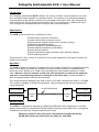
The Integrity Instruments RCE-1 allows the user to monitor contact status at one location, and send these signals to a remote location. The system is bi-directional allowing
contact status at the remote location to be sent back to the other end. Up to 8 inputs at
each end can be sent as outputs to the other end. The uniqueness is that this is done
over a single set of twisted pair wires using rs-485 communications.
Applications
The RCE-1 can be used for a multitude of uses.
Remote alarm indication and reset.
Contact control from a remote source.
Physical status (loading doors open, pumps running).
Production operational status.
Manned operations acknowledgement.
Remote physical positioning operations.
Remote access control.
Physical operations (open windows, start watering pumps)
Remote lighting control.
These are but a few, if there is a need for any remote operations, the remote contact extender is the answer.
Operation
The RCE-1 system consists of a master slave set. Power to each unit is supplied from the
area it is at. When the units are powered a communication protocol is maintained between the units. Similar to a “watch dog” operation the units send information to each
other. When an input is sensed at one end, this information is sent to the opposite
end and a corresponding output is activated at the other end. If communication is
lost, all outputs at both ends are de-activated.
The communications between the units is done via rs-485. Normal baud rate is 115,200K.
The rs-485 is capable of 4,000 foot distances. Using repeaters this can be increased almost indefinitely.
up to 8 inputs
Master
up to 8 outputs
Control
Unit
rs-485 twisted pair
Slave
up to 8 inputs
Control
Unit
up to 8 outputs
RS-485 Cabling
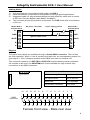
The RCE-1 is designed to operate in a Multi-Drop RS-485 LAN configuration. In a halfduplex mullti-drop environment all RS-485 nodes share the same data lines. A single pair
of data lines act as both Transmit and Receive wires.
Data lines (A/B) are the only wires required between RS-485 nodes
All RS-485 nodes need not share the same V+ and GND
2