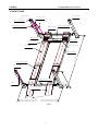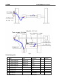
1
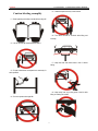
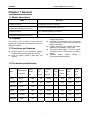
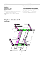
LAUNCH TLT440(440W),TLT455(455W) USER’S MANUAL USER’S MANUAL This equipment is for the use of professional technical personnel or maintenance personnel. Copyright reserved! Without the written agreement of Launch Shanghai Machinery Co., Ltd. (hereinafter called “Launch”), no company or individual is allowed to copy and backup this manual in any form (electronic, mechanical, photocopy, recording or other forms). This manual is specifically designed for the use of Launch product, and our company doesn’t undertake any responsibility for various consequences caused as a result of applying it to the guidance of operating other equipment. Registered Trademark Launch has registered its trademark in China and several foreign countries, with the symbol of LAUNCH. Other trademarks, service symbol, domain name, icon, and company name of Launch mentioned in this manual belong to the property of Launch and its subsidiary companies. In the countries where Launch’s trademark, service symbol, domain name, icon and company name haven’t been registered, Launch declares its ownership on such unregistered trademark, service symbol, domain name, icon and company name. The trademarks of other products and company names mentioned in this manual still belong to the originally registered companies. Without prior written agreement of the owner, nobody can use the trademark, service symbol, domain name, icon and company name of Launch and other companies mentioned in this manual. If you have any question, please visit website of Launch: http://www.cnlaunch.com or write to Sales Dept. of Launch Shanghai Machinery Co., Ltd. at No. 661 Baian Road, International Automobile City Auxiliary Parts Park, Anting Town, Jiading District, Shanghai City to contact Launch. In case of the equipment damage or loss due to the accident of the user himself or third party, abuse or misuse of this equipment, unauthorized change and repair of this equipment, or not conforming to the operation and maintenance requirement of Launch, Launch and its branches won’t undertake any responsibility for the expenses and expenditures generated. For the equipment damage or problem caused as a result of using other optional accessories or consumables instead of original Launch product or its recognized product, Launch won’t undertake any responsibility. Official statement: The purpose of other- product- names mentioned in this manual is to describe how to use this equipment. Their registered trademarks still belong to the original companies. i LAUNCH TLT440(440W),TLT455(455W) USER’S MANUAL To reduce the risk of fire, do not operate equipment in the vicinity of open containers of flammable liquids (gasoline). z During the machine operation, non-operators should be kept away from the machine. z Do not operate equipment with a damaged cord or the equipment has damaged or lost parts, until examined by a qualified serviceman. z The lift can’t be overloaded. The rated load of the lift is already marked on the nameplate. z Please don’t raise the lift when there are people in the vehicle. During the operation, the customer and spectators should not be in the lifting area. z Keep the lifting area free from obstacle, grease, machine oil, garbage and other impurities. z Contact the lifting point as recommended by the manufacturer. z For some vehicles, the parts dismantling (or installation) will cause severe deviation of the center of gravity, leading to unstable vehicle. The support is needed to keep the balance of the vehicle. z Before moving the vehicle away from the lifting area, please position the rolling jack in front of the runway to avoid blockage during the movement. z Use appropriate equipment and tools as well as safety protection facilities, e.g. working uniform, safety boot, etc. z Pay special attention to various safety marks attached to the machine body. z Keep hair, loose clothing, fingers, and all parts of body away form moving parts z Pay special attention not to dismantling the safety devices of the machine or making it not functioning. z The hydraulic oil used for this lift is N32 or N46. Please refer the safety data of grease and oil shown in the manual. Launch Shanghai is dedicated to improve the product quality and upgrade the technical spec. They are subject to change without notice. z PRECAUTION WARNING z z z z z This instruction manual is an essential integral part of this product. Please read all instructions. Properly keep this manual for use during the maintenance. Use only manufacturer’s recommended adapters. This equipment is only used for its clearly designed purpose, and never use it for other purposes. The manufacturer is not responsible for any damage caused as a result of improper use or use it for other purposes. IMPORTANT SAFETY INSTRUCTIONS When using your garage equipment, basic safety precautions should always be followed, including the following: z Only the qualified personnel having undergone special training can operate this machine. Without the permission of the manufacturer or not following the requirement of the manual, any changes in the machine part and in the usage scope may cause direct or indirect damage to the machine. z Don’t keep the lift in the extreme temperature and humidity environment. Avoid installation beside the heating equipment, water tap, air humidifier or stove. z Prevent the lift from contacting large amount of dust, ammonia, alcohol, thinner or spray adhesive, and prevent it from rain shower. z Always disconnect equipment from electrical supply when not in use. Never use the cord to pull the plug from the outlet. Grasp plug and pull to disconnect. z To reduce the risk of electric shock, do not use on wet surfaces or expose to rain. ii LAUNCH TLT440(440W),TLT455(455W) USER’S MANUAL (5)Authorized personnel only in the lift area! Caution labeling exemplify (1)Read operating and safety manuals before using lift! (6)The vehicle should be chocked while lifting and lowering (2)Lift can be used by trained operators ONLY! (7)Keep the area clear when there is risk of vehicle falling. (3)Proper maintenance and inspection is necessary for safe operation! (8)Keep away from any moving parts of the lift while lifting or lowering the vehicle. (4)Don not operate a damaged lift! ii LAUNCH TLT440(440W),TLT455(455W) USER’S MANUAL ( 9 ) Don’t adjust the hydraulic pressure without permission. Table of contents Chapter 1 General 1 1.1 Model 1 1.2 Purpose 1 1.3 Functions and features 1 1.4 Technical specifications 1 1.5 Environment Requirements 1 Chapter 2 Structure (10)Keep the feet away from the lift while lowering the lift! (11)When lifting or lowering the runways, don’t stand on the lift or under the lift. ... 2 Chapter 3 Operating instruction 4 3.1 Precautions for Operation 4 3.2 Operating preparation 4 3.3 Inspection before Operation 4 3.4 Lifting the vehicle 4 3.5 Lowering the vehicle 4 Chapter 4 Solutions to FAQ 5 Chapter 5 Repair and Maintenance 6 Chapter 6 Storage and Scrap 8 6.1 Storage 8 6.2 Scrap 8 Chapter 7 Hydraulic system, electrical system and iii pneumatic system 8 7.1 hydraulic system 8 7.2 pneumatic system 9 7.3 electrical system 10 Safety datasheet for lift oil and grease 11 LAUNCH TLT440 (440W) USER’S MANUAL Chapter 1 General 1.1 Model description Model Description TLT440 Four-Post Lift 4-T (9000 lbs) Economy Four-Post lift TLT440W Wheel Alignment Four-Post Lift 4-T (9000 lbs) Wheel Alignment Four-Post Lift TLT455 Four-Post Lift 5.5-T (12000 lbs) Economy Four-Post lift TLT455W Wheel Alignment Four-Post Lift 5.5-T (12000 lbs) Wheel Alignment Four-Post Lift z 1.2 Purpose This machine is used for lifting of various small and medium-sized vehicles with total weight below 4.0t/5.5t in garage and workshop. 1.3 Functions and features z z z z z Designed based on the international standard, meeting the demand of the garage and workshop. Driven by hydraulic cylinder in stable lifting and lowering. z Offering full-range mechanical safety protection by using the safety latches. Connected by four steel cables; forced synchronized movement of the lift in order to effectively prevent the sloping of the vehicles. Equipped with rolling jack, turntable and sideslip, suitable for wheel alignment. ( 440W, 455W) The minimum lifting height of TLT440 is 170mm, TLT440W is 220mm, TLT455 is 200mm, TLT455W is 248mm. Adjustable distance between runways to accommodate different wheel track. 1.4 Technical specifications Lifting height mm Lifting time Second Lowering time Second Motor power Kw Width between columns mm Overall width mm Overall height mm Model Rated capacity Tonnage(lbs) TLT440 4 (9000) 1900 ≤60 ≥20≤40 2.2 3000 3445 2172 TLT440W 4 (9000) 1900 ≤60 ≥20≤40 2.2 3000 3445 2172 Rolling jack 2(4500) 250 TLT455 5.5 (12000) 1900 ≤75 ≥20≤40 3 3045 3445 2172 TLT455W 5.5 (12000) 1900 ≤75 ≥20≤40 3 3045 3445 2172 Rolling jack 2(4500) 250 1 LAUNCH TLT440 (440W) USER’S MANUAL Noise Operating noise: ≤ 80dB(A) Single phase: 220V/60Hz, 2.2KW Three phase: 380V/50Hz, 2.2Kw Hydraulic unit Working pressure:16MPa Electrical parameters: Motor: Voltage: The motors of different voltages can be selected based on customer’s requirements. Single phase: 110v/60Hz 2.2KW;220V/50Hz 2.2Kw 1.5 Environment requirements Operating temperature: -5℃~+40℃Relative humidity: Temp. +30℃,relative humidity 80% Transportation/storage temperature:-5℃ ~ +40℃Applicable altitude: no more than 2000m Chapter 2 Structure of lift TLT440,TLT455 FL Column FR Column Air Control valve 0) Front Cross Tube 170 ( 20 Power Unit Left Runway 5 72 5 ) Right Runway 45 55 ( Cables RL Column RR Column 23 5 217 2 Rear Cross Tube Drive On Ramp 500(550) 950(1000) 500(550) 3445 Fig.1 2 LAUNCH TLT440 (440W) USER’S MANUAL TLT440W,TLT455W FL C olumn FR C olumn Pow er Un it Ai r Lub ricato r Oil H ose Fr ont C ross Tube C ontro l Air Valve Wh eel S top Fron t Cov er Tur n Tabl e Fro nt Ra mp Rol ling Jack Le ft Run way 4555 (572 5) Rig ht Ru nway Side Slip Plate 2 17 45) Rea r Cro ss Tub e 2 RL Colum n (2 1 70 Cable Drive On Ra mp 500 (550) 9 50(100 0) 500( 550) 3 445 Fig.2 2 LAUNCH TLT440 (440W) USER’S MANUAL z z Chapter 3 Operating instruction z z 3.1 Precautions for Operation z z z z The gravity position and wheel distance are different for various vehicles. When the vehicle drives on the lift, try best to put its gravity in the middle of the lift. When doing the turntable operating, put the front wheel in the middle of the turntable. Carefully read the warning decals. The hydraulic valves have been properly adjusted before ex-works, so the users shall not make unauthorized adjustment, otherwise, all the consequences shall be borne by user. Based on the production demand, some parameters in the instruction manuals may be modified. 3.2 Operating preparation z z Lubricate the all moving parts in the front and rear cross tubes and the rolling jack mechanism. The power unit oil tank shall be filled with 12 L N32 or N46 applied for hydraulic system. Move the vehicle to the middle of the lift. Press the start button on the power unit to lift the vehicle slowly in order to ensure the loading balance and then raise the lift up to the required height. Release the start button. Press the lowering handle to lock the lift, then the vehicle can be repaired. Notes: When lifting the vehicle, the chocks must be used to block the wheel. Prior to the lifting of the vehicle, check for the oil leakage of all the hoses and joints. In case of leakage, the lift shall not be used. Dismantle the leaking joints for resealing. Re-mount the joint and recheck for the oil leakage. When the vehicle is lifted, please confirm the safety devices are under working conditions. 3.5 Lowering the vehicle z Remove the obstacles from under z For lowering the lift, If the locking latches are engaged, lift must be raised enough for all 4 latches to clear the latch plates slots inside the columns. Actuate the air control valve to 3.3 Inspection before Operation z z z z z disengage all 4 locking latches and push the Check to see if the power supply is installed properly. Check to see the compressed air supply. Check to see if all the bolts are fastened. Check to see if the cable tension is well adjusted. Check to ensure no air or hydraulic leakage in the lift. 3.4 Lifting the vehicles z z Remove the foreign articles around the lift. Lower the lift to the bottom. 3 z z lowering handle on the power unit to lower the lift. Lower the lift down to the bottom and release the lowering handle. To lower the rolling jack, raise jack and release locking latch by lifting release handle, and then depress lowering valve. LAUNCH TLT440 (440W) USER’S MANUAL Chapter 4 Solutions to FAQ Symptom ♦ The motor doesn’t run ♦ ♦ ♦ ♦ The motor runs but doesn’t lift the lift Motor is running, the lift can be raised without load, but the vehicle can’t be raised ♦ ♦ ♦ ♦ ♦ ♦ ♦ ♦ Causes Check the fuse or the circuit breaker Check for the voltage supplied to the motor Check all the wiring The motor winding is burnt out Reverse rotation of motor ♦ ♦ ♦ Lowering valve normally open Air into the hydraulic pump Air suction pipe goes off the hydraulic pump Low oil level Motor operating under low voltage Impurities inside the lowering valve Incorrect adjustment of the safety valve Overloading of lift ♦ ♦ ♦ ♦ ♦ ♦ ♦ ♦ Supply the correct voltage to the motor Remove the impurities inside the valve Adjust the safety valve Check the weight of the vehicle and/or balance the weight of the vehicle on the lift ♦ ♦ ♦ Clean the lowering valve Repair the external leakage Replace the check-valve ♦ ♦ Replace the hydraulic oil Tighten all the connections for the air suction pipe Re-install the oil return pipe Adjust the cables to the proper tension Shimming the columns to level the lift, If exceeding 12mm, pour new concrete floor and make it leveled. Refer to installation description The lift is lowering slowly without pressing the lowering valve ♦ ♦ ♦ Existence of impurities on the seat of the lowering valve External oil leakage Check-valve leakage Slow lifting speed or oil flowing out of the oil cap ♦ ♦ ♦ Mixture of air and oil Air and oil sucked air mixed Loosening of oil return pipe ♦ ♦ The 4 cables is not well-adjusted The lift is installed on the floor where levelness can’t meet the requirements ♦ Oversized drilled hole ♦ Insufficient thickness or tightening force of the concrete floor The lift can’t rise horizontally The anchor bolt is not tightened ♦ Solutions Replace the burnt fuse or reset the circuit breaker Supply the correct voltage to the motor Repair and isolate all the wirings Replace the motor ♦ ♦ ♦ ♦ ♦ 5 ♦ Change the motor rotation direction by converting the lead wire of the motor Repair or replace the lowering valve Tighten all the air suction piping connections Replace the air suction pipe Add oil into the oil tank Pour the fast curing concrete into the big hole and reinstall the anchor bolt, or use new drill to drill the hole for re-positioning the lift Cut open the old concrete and make new concrete slab for the lift. Refer to installation description. LAUNCH TLT440 (440W) USER’S MANUAL Chapter 5 Repair and z Maintenance Keep clean z z oil cylinder are loosened off or not. See Figure 6. Check whether the steel cables are in normally condition and whether the tension is under the optimum conditions. Replace the worn or damaged cables immediately. Monthly: The working environment of this unit should be clean. In case of dust in the working environment, it will speed up the parts wearing and shorten the service life of the lift. This unit should be cleaned with dry cloth frequently to keep it clean. Before cleaning, first switch off the power to ensure the safety z z z z Re-tighten the anchor bolts. Lubricate the shaft and wheel of each rotating part. Check all the connection bolts and pins in order to ensure correct installation. Check for the wear and damages of the hydraulic hoses. Note: all the anchor bolts shall be completely Daily: z Before the operation, carefully check the safety mechanism of the lift to ensure the lock and release action is proper, and the safety latch is in good condition. When finding any abnormal situation, make adjustment, repair or replacement immediately. tightened; in case of failure of the anchor bolts, the lift shall be stopped until the replacement of the anchor bolts. Every six months: z z z 1 z 2 Maintenance and preservation of the hydraulic system: z Cleaning, replacing the oil After six months upon the initial operation of this machine, the hydraulic system shall be cleaned once a year and the oil shall also be changed. See Figure 4. z Replacing the sealing parts After certain time use of this machine, if the oil leakage is found, careful check shall be conducted; if the leakage is caused due to the wear of the sealing materials, the timely replacement shall be made based on the original specification. See Figure 4. 3×36 GB91-86 z Check for the wear, interference or damage to all the moving parts. Check for the lubrication of all the sheaves. In case of hauling of the sheaves occurring during the lifting and lowering operation, suitable amount of lube oil shall be added to the axles. If necessary, check and adjust the balancing tension in order to maintain the horizontal lifting and lowering. Check the verticality of the column. Figure 3 Check for the normal connection between the hydraulic cylinder and the cylinder runway front plate, and whether the lock nuts and the connections of the 6 LAUNCH TLT440 (440W) USER’S MANUAL Fig.4 List of wear parts No. Title Model Specification Qty. 1 “0”rubber sealing ring GB3452.1-92 69×5.3 1 “0”rubber sealing ring GB3452.1-92 53×5.3 1 2 “0”rubber sealing ring GB3452.1-92 14×2.65 4 3 “0”rubber sealing ring GB3452.1-92 7.5×1.8 9 4 Dust proof ring DH40 1 5 Dust proof ring DH40 1 6 Axle seal ring UHS70×80×6 1 7 Axle seal ring UHS53×63×6 1 7 Comments LAUNCH TLT440 (440W) USER’S MANUAL Chapter 6 Storage and Empty all the oil/liquid storage units Put the plastic cover over the equipment for dust protection. z z scrap 6.2 Scrape 6.1 Storage When the equipment service life is expired and can no longer be used, disconnect the power supply, and properly dispose of as per relevant local regulations. When the equipment requires long-time storage: z Disconnect the power supply z Lubricate all the parts requiring lubrication etc. Chapter 7 Hydraulic system, electrical system and pneumatic system Diagram of hydraulic system: 9 6 P 4 5 7 8 2 M 1 11 3 1.Gear Pump 2.Motor 3.Filter 4.Check-Valve 5.Safety Valve 6.Release Valve 7.Flow Control Valve 9.Cylinder 10.Oil Level Gauge 8 LAUNCH TLT440 (440W) USER’S MANUAL Diagram of Pneumatic system: TLT440W, TLT455W 3 2 B AP 5 4 S PR X Y 1 1 . Ai r S o u rc e 2. A i r Con t rol V al v e 3 . Ai r C y l in d e r 4 P n eum a tic Pu m p 5 C yli nd e r TLT440, TLT455 3 2 B AP SPR 1 气源 两位 五 通拨 动 式换 向 阀 单 出杆 气 缸 1.Air Source 2. Air Control Valve 3. Air Cylinder 9 LAUNCH TLT440 (440W) USER’S MANUAL Diagram of electrical system: KM Contactor ~380V L1 L2 L3 KM SB M 10 LAUNCH TLT440 (440W) USER’S MANUAL Safety datasheet for lift oil and grease No.2 lithium lubricating grease Items Quality index Coning(1/10mm) 278 Dripping point ℃ 185 Corrosion(T2 copper strap,100 ℃,24h) No change on copper straps Oil distribution by copper wire mesh(100℃,22h)% 4 Evaporation (100℃,22h)% 2 Oxidation stability(99℃,100 h) 0.2 Anti-corrosiveness (52℃,48) Level 1 Impurities(by adopting telescope)/(pcs/cm³) Above 10µm not more than Above 25µm not more than Above 75µm not more than Above 125µm not more than 5000 3000 500 0 Similar viscosity ( -15℃ , 10s-1 not more than ) ,/(Pa·s) Water spraying loss(38℃,1h)(%) Not more than 800 8 N32 Hydraulic oil (used under low ambient temperature) Items Quality index Moving viscosity 40℃ 28.8~35 pour point -15 /℃ Flash point /℃ not higher than not lower than 175 N46 hydraulic oil (used under high ambient temperature) Items Quality index Moving viscosity 40℃ 41.4~50.6 pour point -9 /℃ Flash point /℃ not higher than not lower than 185 11 LAUNCH TLT440 (440W) USER’S MANUAL Disclaimer Warranty clause This warranty clause is only applicable for the users and distributors who purchase Launch products through normal sales procedure. Within 12 months from the date of goods delivery, Launch will make warranty on its mechanical and electrical components due to material or process defects. The equipment or parts damage caused as a result of abuse, unauthorized change, not used for the product designed purpose, operation not in accordance with method stipulated in this manual will be outside the scope of this warranty. The compensation for the automobile damage caused because of our equipment defect is only restricted to repair, and Launch doesn’t undertake any indirect or incidental loss. Launch will judge the equipment damage attribute based on its stipulated inspection method. None of Launch’s distributors, staffs or commercial representatives has the right to make any confirmation, prompting or commitment related to Launch’s products. 12 The above warranty clause can replace any other forms of warranty clauses. Order notice The parts and optional accessories that can be replaced can be directly ordered with suppliers authorized by Launch. When placing the order, please indicate: Order quantity Parts number Parts name Customer service In case of any problems during the operation of the equipment, please call: 86-21-69573179 or toll free number 8008206369. No. 661 Baian Road, International Automobile City Auxiliary Parts Park, Anting Town, Jiading District, Shanghai City Launch Shanghai Machinery Co., Ltd. Postcode: 201805