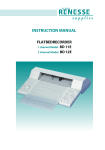
Download Recorder Rec 111 Recorder Rec 112 Recorder Rec 111 Recorder
Transcript
GE Healthcare Recorder Rec 111 Recorder Rec 112 User Manual Important user information All users must read this entire manual to fully understand the safe use of Recorder REC 111 and Recorder REC112. WARNING! The WARNING! sign highlights instructions that must be followed to avoid personal injury. It is important not to proceed until all stated conditions are met and clearly understood. CAUTION! The Caution! sign highlights instructions that must be followed to avoid damage to the product or other equipment. It is important not to proceed until all stated conditions are met and clearly understood. Note The Note sign is used to indicate information important for trouble-free and optimal use of the product. CE Certifying This product meets the requirements of applicable CE-directives. A copy of the corresponding Declaration of Conformity is available on request. The CE symbol and corresponding declaration of conformity, is valid for the instrument when it is: – used as a stand-alone unit, or – connected to other CE-marked GE Healthcare instruments, or – connected to other products recommended or described in this manual, and – used in the same state as it was delivered from GE Healthcare except for alterations described in this manual. Recycling This symbol indicates that the waste of electrical and electronic equipment must not be disposed as unsorted municipal waste and must be collected separately. Please contact an authorized representative of the manufacturer for information concerning the decommissioning of equipment. Contents Contents 1 Introduction 2 General Description 2.1 2.2 2.3 2.4 2.4.1 2.4.2 2.4.3 2.4.4 2.4.5 2.4.6 2.4.7 2.4.8 2.4.9 2.4.10 2.4.11 Top view ...................................................................................................................................9 Rear panel view ................................................................................................................. 11 Left-hand side view ......................................................................................................... 12 Chart drive description .................................................................................................. 12 Record off-on ............................................................................................................................... 12 Chart speed .................................................................................................................................. 12 Internal-external ......................................................................................................................... 13 Paper transport........................................................................................................................... 13 Home and set .............................................................................................................................. 13 Go to next grid mark ................................................................................................................ 13 Servo system ............................................................................................................................... 13 Sensitivity ...................................................................................................................................... 14 Calibrated-variable span ........................................................................................................ 14 Zero and zero adjust................................................................................................................. 14 Pen up-down ................................................................................................................................ 14 3 Installation 3.1 3.2 3.3 3.4 3.5 3.6 3.7 3.8 3.9 3.10 Unpacking ............................................................................................................................ 15 Safety instructions for power connection ............................................................ 15 Electrical connections .................................................................................................... 15 Loading the chart paper roll ....................................................................................... 15 Writing system................................................................................................................... 17 Connecting the input signals ...................................................................................... 17 External control ................................................................................................................. 18 Event mark ........................................................................................................................... 19 Chart drive ........................................................................................................................... 19 Remote chart ON/OFF control of chart drive ...................................................... 19 4 Operation 4.1 4.2 4.3 Operation in ”panel” mode .......................................................................................... 21 Operation in ”external” mode by external pulses ............................................. 21 Home and grid function ................................................................................................ 22 Record Rec 111, Recorder REC 112 User Manual 18-1132-20 Edition AD 5 Contents 5 Maintenance 5.1 Recycling .............................................................................................................................. 23 6 Trouble-shooting 6.1 6.2 6.3 6.4 6.5 General .................................................................................................................................. 25 Recycling .............................................................................................................................. 25 Chart drive ........................................................................................................................... 25 Chart speed ......................................................................................................................... 25 Pen system .......................................................................................................................... 26 7 Technical Specifications 8 Accessories and Spare Parts 9 Applications 9.1 6 Volume-axis......................................................................................................................... 33 Record Rec 111, Recorder REC 112 User Manual 18-1132-20 Edition AD Introduction 1 Introduction GE Healthcare model REC 111 (Code No. 18-1132-32), single-channel recorder and model REC 112 (Code No. 18-1132-33), dual-channel recorder are compact recorders designed to meet the challenging demands of today´s technology. These instruments are high quality, flat-bed recorders from GE Healthcare which use a null balancing potentiometric system. They can accommodate a range of input voltages, offer a selection of chart speeds, and allow many functions to be remotely controlled. The recorders have sophisticated features such as electric pen lift, grid and home functions, forward and reversed paper feed. Paper is transported at a constant velocity selected from the 14 different chart speeds in the range from 0.1 mm/min to 20 mm/s, and can be synchronized with the pump to enable chromatogram comparision. The positions of the two independent pens (REC 112) represent the levels of the two corresponding inputs from which the time functions are drawn. Owing to the nature of the dual-channel recorder, the pen of channel 1 is always 2.5 mm behind the pen of channel 2. Full sensitivity ranges from 1 mV to 20 V DC. Recorder (REC 112) is equipped with one chart drive control panel and two independent, isolated servo systems with a control panel for each channel. Recorders REC 111 and REC 112 have an attractive design with much attention having been paid to ergonomics: control functions are well positioned, keys and switches are very accessible, and paper is easily changed. The pens, which are non-smear and disposable, give clear, accurate traces for instance evaluation. Chart paper is of a high quality, and 200 mm wide. Improved control capabilities permit the use of these recorders in all GE Healthcare chromatography systems. Record Rec 111, Recorder REC 112 User Manual 18-1132-20 Edition AD 7 Introduction 8 Record Rec 111, Recorder REC 112 User Manual 18-1132-20 Edition AD General Description 2 General Description 2.1 Top view 1 8 16 10 9 7 10 15 14 11 12 3 2 6 4 5 Fig 1. Model REC 112 No Item Description Servo system (one for each channel) 1 range selector Rotary switch with 14 positions selects span settings, ranging from 1 mV to 20 V FSD (full scale deflection) 2 cal.var. span 2-position key selects between calibrated and user adjustable span 3 var. adjustment Potentiometer to set the range from 40% to 100% FSD by means of a screwdriver 4 zero 2-position key switches one channel amplifier input to zero, used for zero adjustment of the pen. The recorder zero may be checked at anytime during operation, without changing any other settings. The zero is, as default, set to the right-hand side of the chart paper Note: The recorder response will not be activated unless the “zero” key is in the “up” position. 5 zero adjustment Potentiometer with rotating knob, used to position the pen on the paper 6 pen up-down 2-position key used to activate the electrical pen lift (pen 1 and pen 2 are independent) Record Rec 111, Recorder REC 112 User Manual 18-1132-20 Edition AD 9 Geneal Description No Item Description Chart drive (left-hand side of each channel) 7 rec. off-on 2-position key selects: record off mode: keyboard control of chart drive; forward, reverse, home, zero, set and go to major grid mark record on mode: internal chart speed settings or external pulse input and remote control functions 10 8 chart speed 8-position rotary switch for fixed chart speed settings (0.1, 0.2, 0.5, 1, 2, 5, 10 and-20) 9 mm/s – /min 2-position key changes selected chart speed unit from mm/s to mm/min 10 int.-ext. 2-position key changes between keyboard selected chart speed and external chart pulse input 11 feed Transports the paper forwards with increasing speed 12 feed Transports the paper backwards with increasing speed 13 set Defines start of plot and major grid mark position 14 home Moves the paper to start of plot position (with pen up) 15 grid Moves the paper (always forward) to the next major grid mark (lines with 10 mm distance). When on grid mark the paper moves one grid mark further 16 power Green LED indicates power on Note: 11 12 13 14 15 The following functions are only available in record off mode feed feed set home grid Record Rec 111, Recorder REC 112 User Manual 18-1132-20 Edition AD General Description 2.2 Rear panel view 18 22 17 19 20 21 23 Fig 2. Model REC 112 No Item Description 17 Analogue input, (banana plug, channel 1, shortnib pen) The input signal is connected to the terminals on the rear panel y banana plugs 18 Analogue input (banana plug, channel 3, longnib pen) Same as above 19 External control A 15-pin D-sub connector for remote control of the recorder 20 Zero position selector 2-position switch used to select left or right-hand-zero position 21 Mains voltage selector 2-position switch used to select appropriate voltage range: 100–120 V (covers 93.5 to 132 V) 220–240 V (covers 187 to 264 V) 22 Chassis ground Earth point to other instruments 23 Mains power inlet Inlet for the mains cable Record Rec 111, Recorder REC 112 User Manual 18-1132-20 Edition AD 11 General Description 2.3 Left-hand side view 25 24 Fig 3. Model REC 112 No Item Description 24 Mains power switch Switches the recorder ON/OFF 25 Fuse holder 100–120 V fuses 250 mA 220–240 V fuses 125 mA 2.4 Chart drive description 2.4.1 Record off-on The function of this key is to start and stop paper transport. When “rec.off-on” key is in the “off” position, it interrupts both the internal chart speed pulses and the external pulses. This key must be set in the “off” position to operate any of the following functions: “feed” (arrows), “home”, “grid” and “set”. When “rec.off-on” is in the “on” position the above keys will not operate. 2.4.2 Chart speed The velocity at which the paper moves is controlled by a combination of two functions. One is “chart speed” of which there are eight possible positions between 0.1 and 20 units. The other is the applied unit which is either mm/min or mm/s. Together these give a lowest speed of 0.1 mm/min, at which the paper roll has an expected lifetime of 4–100 hours and a highest speed of 20 mm/s, at which the paper roll lasts approx. 20 minutes. 12 Record Rec 111, Recorder REC 112 User Manual 18-1132-20 Edition AD General Description 2.4.3 Internal-external The position of this key determines the source of the pulses driving the paper. When the key is in the “int.” position an internal counter is in operation. When in the “ext.” position the chart drive must be fed with pulses from an external source (see Section 3.6). 2.4.4 Paper transport The keys for this function are marked with two arrows. With these keys the paper can be accurately positioned underneath the pens. Each time one of these keys is pressed for less than one second, the paper moves a distance of 0.05 mm forwards or backwards. If the key is depressed for longer than one second, the paper will move at a speed of 2 mm/s. The paper will continue to move at this speed for the next five seconds, corresponding to a distance of 10 mm. After depressing the key for six seconds, the paper will start moving at a speed of 20 mm/s. These paper feed keys facilitate quick and accurate positioning of the paper under the pens. The paper can only be transported in this manner when the “rec.off-on” key is in the “off” position. 2.4.5 Home and set Pressing the “home” key will return the pens to where the origin is located. This is either the position of the pens during powering up or the position of the pens at the moment key “set” was last pressed. This key is used to define a new origin at any position. These keys can only be operated when the “rec.off-on” key is in the “off” position. 2.4.6 Go to next grid mark This function is activated by pressing “grid”. Each time this key is pressed, the paper advances 10 mm, which is the distance between the grid marks printed on the recorder paper. When the origin has been set precisely over a grid mark, pressing “grid” will always advance the pen to the next grid mark. Paper is transported at a velocity of 20 mm/s. This function only operates when “rec.off-on” key is in “off” position. 2.4.7 Servo system The REC 111/112 is equipped with two fully independent servo systems. Each servo system has an operator panel which controls its functions. The following explanation of these functions holds equally well for both channels. The signals that are to be recorded must be connected to the corresponding input terminals on the rear panel of the recorder. The black terminal(s) are for the negative side(s), the red terminal(s) for the positive side(s). WARNING! For personal safety, the maximum input voltage across each of the channel terminals should not exceed 30 V/AC or 42 V/DC. Record Rec 111, Recorder REC 112 User Manual 18-1132-20 Edition AD 13 General Description 2.4.8 Sensitivity The input sensitivity of each channel is selected with the “range” rotary switch, which has 14 positions. Turned fully counter clockwise, a sensitivity of 20 V is attained. This means that an input voltage of 20 V will move the pen all the way from the right-hand edge to the left-hand edge of the paper (zero position set to the right side of the paper). When the “range” switch is turned fully clockwise, the sensitivity is 1 mV full scale. The whole range between these sensitivities is covered in 14 steps according to the sequence 1, 2, 5, 10, 20, 50 mV and 0.1, 0.2, 0.5, 1, 2, 5, 10, 20 V. The input sensitivities have these calibrated values only when the “cal.-var.” key is in the “cal.” position. 2.4.9 Calibrated-variable span When the key “cal.-var.” is in the “cal.” position an input signal equal to the selected range will result in a full scale deflection (FSD). However, it is sometimes desirable to have an input span which lies between the values chosen with the range switch. In such cases, the “cal.-var.” key must be in the “var.” position, after which the variable span can be adjusted by turning the potentiometer with the fingertip or the aid of a small screwdriver. Example: Suppose a signal varying between 0 and 25 mV has to be recorded and one wants to use the full scale width. 1 Select the 50 mV range. 2 Put the “cal.-var.” key in the “var.” position. 3 With a 25 mV signal connected to the analogue input adjust the potentiometer until the amplitude reaches 100 % of scale. Since the variable span allows 40 % to 100 % span adjustment, any desired (noncalibrated) span between 0.4 mV to 25 mV can be obtained. 2.4.10 Zero and zero adjust When the “zero” key is in the down position, the pen will remain at its zero location. This is the electrical zero of the pen in the absence of an input voltage. The location of this point can be shifted to the left or right by turning the zero knob. This function allows relocation of the zero point anywhere between the left and right edge of the paper. After the zero location has been chosen, the recorder must be put back into operation. Press the “zero” once again to release the key. Note: On delivery the recorder zero position is factory set to right-hand zero. 2.4.11 Pen up-down This key controls vertical movement of the pen. If there has been no chart drive pulse for a period of 30 seconds, the pen(s) will be automatically lifted off the paper. This prevents ink stains on the paper. For this function to operate the “rec.off-on” key must be in the “off” position and pen “updown” key in the “down” position. It also operates when the paper transport is controlled externally and chart drive pulses have stopped. 14 Record Rec 111, Recorder REC 112 User Manual 18-1132-20 Edition AD Installation 3 Installation 3.1 Unpacking CAUTION! The system should be installed on a stable laboratory bench providing a suitable working area. Carefully unpack Recorder REC 111 or Recorder REC 112. Check the contents against the packing list supplied. Inspect for any damage that may have occurred during transit. Report any damage immediately to the local GE Healthcare representative concerned. Save the packing material if future transport can be foreseen. 3.2 Safety instructions for power connection WARNING! Only use mains cables delivered or approved by GE Healthcare. WARNING! Do not block the rear panel of the system. The mains power switch must always be easy to access. Ensure that the protective mains earth is functioning correctly before you connect the equipment to the mains. Connect the instrument to a protective earth conductor via the three-core mains cable before making any other connection. Insert the mains plug only into a socket outlet provided with a protective earth contact. Do not use an extension cord without a protective conductor. WARNING! Any interruption of the protective conductor inside or outside the instrument, or disconnection of the protective earth terminal, is likely to make the instrument dangerous. Intentional interruption is prohibited. Make sure that only fuses of the required type and current rating (250 mA for 100–120 V operation and 125 mA for 220–240 operation) are used for replacement. The use of repaired fuses, and/or short-circuiting of fuse holders is prohibited. Fuses should only be replaced by qualified persons who are aware of the hazards involved. Note: Adapting the mains plug to local conditions should only be done by a qualified person. WARNING! Disconnect the instrument from all sources when replacing a fuse or when adapting the instrument to a different voltage. 3.3 Electrical connections The instrument is supplied with mains cable and fuses for both 100–120 V and 220–240 V operation. 1 Ensure that the mains power switch on the left side is in the OFF position (Fig. 3:27). Record Rec 111, Recorder REC 112 User Manual 18-1132-20 Edition AD 15 Installation 2 Check that the mains voltage selector is set to mains voltage of the laboratory (Fig. 2:23). 3 Select the correct fuses from the fuse kit supplied. For 100–120 V operation, use the 250 mA fuses supplied. For 220–240 V operation, use the 125 mA fuses supplied. Insert the fuse into the fuse cap, and then fit the fuse cap into the fuse holder socket on the left side of the instrument (Fig. 2:28). Discard the unwanted fuses immediately. 4 Select and connect the mains cable corresponding to your mains supply. Discard the unwanted mains cable immediately. WARNING! To comply with electrical safety standards the signal voltage should never exceed 30 Volt. 3.4 Loading the chart paper roll Unpack the paper roll supplied with the recorder and put into place (Fig. 4a). Ensure the paper roll is positioned so that the printed grid faces the user during normal operation. Lift the plastic transparent ruler (Fig. 4 b), pushing it gently upwards so that it rests over the top of the recorder. Leave it in this position. Pull the paper forward, it should be parallel to the recorder housing. With your fingertips fit the holes in the edge of the paper over the sprockets. Do this on the right-hand side first and then on the left-hand side (Fig. 4 c). This is important because the holes in the right side guarantee exact paper positioning whereas the holes on the left side only support transport. When the paper is correctly positioned over both sprocket wheels, hold the paper in position and lower the ruler. Then with both hands gently apply pressure to both the left and right edge of the ruler. A double click indicates that the ruler is properly positioned. Fig 4a. Fig 4b. Fig 4c. 16 Record Rec 111, Recorder REC 112 User Manual 18-1132-20 Edition AD Installation 3.5 18-1004-23 Writing system GE Healthcare Recorders REC 111 and REC 112 have a writing system that is very simple and convenient. They use reliable fibre-tip pens of the disposable cartridge type (Figs. 5 a and b), which leave a very fine trace and do not bleed. To install the pens, remove the cap and gently push the pen into the plastic pen holder, avoiding sidewards or upwards pressure. Note: To prevent the pens drying out when the recorder is not in use, cover the tips of the pens with the caps provided. 18-1004-22 Fig 5b. Fig 5a. 3.6 Connecting the input signals The input signal is connected to the analogue input terminals on the rear panel by banana plugs (Fig. 2:17 and/or Fig. 2:18). The input signals should be connected as follows: Red terminal = + High-lead with the highest impedance to ground (positive). Black terminal = – Low-lead with the lowest impedance to ground (negative). Metal terminal = – Ground-shield or ground lead. The input signal should be carried by properly shielded leads to avoid the AC hum and noise. Excessive hum and noise at the input may cause the pen to oscillate with high frequency. Note: When connecting UV Monitors UV-1 and UV-M II, Conductivity Monitor or pH Monitor from GE Healthcare, connect the pin connectors supplied with the recorder to the monitor signal cable(s). Record Rec 111, Recorder REC 112 User Manual 18-1132-20 Edition AD 17 Installation 3.7 External control The recorders REC 111 and REC 112 can be remotely controlled in a GE Healthcare chromatography system as well as by instruments from other suppliers. There is a 15-pin D-sub connector on the rear of the recorder which enables remote control of the recorder. The following functions are available from the 15 pin D-sub connector. Signal logic/pin numbers** Function x/0/ Go to grid mark 4 x/0/ Event mark channel 1 6 0/ Event mark channel 2 7 x/*/+/ Pen lift channel 1 1 x/*/+/ Pen lift channel 2 x/ Chart drive pulse input x/0/ Home x/*/ Chart ON/OFF x/0/ Start of plot/major grid mark Signal GND ** * 0 + 15-pin D-sub Pin No. 2 14 8 12 3 10, 15 x only available in “rec.on” mode default active ´0´(´1´selected internally by strap) active ´0´ or contact closure to ground only available when panel keys (pen) are in pen “down” position Note: In order to supress unwanted interference from external origin, all inputs, except ECP (External Chart drive Pulses) and servomarker, are filtered. Any pulse that is shorter than 40 ms is rejected. As a consequence, these signals are always delayed by 40 msec. When an external chart drive pulse is used to move the paper under the pens, a socalled dividend is applicable. This is a number between 1 and 12 000, by which the number of received pulses is divided, before one step is made (i.e. 0.05 mm). The value of this dividend depends on the positions of the key “mm/min” or “mm/s” and the rotary switch “chart speed”. Switching from “mm/s” to “mm/min” increases the dividend by a factor of 60, and turning “chart speed” from 20 towards 0.1 accounts for a factor of 200. The combination of these two results in a maximum dividend of 60 x 200 which equals 12 000. The maximum frequency at which ECP may be sent to the REC 111/112 recorders is 8 kHz. (Pulse duration at least 1 µsec). Since the maximum stepping rate, corresponding to a maximum chart speed of 20 mm/s and a step size of 0.05-mm, equals 400 Hz, this maximum ECP frequency can only be handled properly by the recorder if a dividend value of at least 25 is applicable. The user is responsible for maintaining this lowest value. If the stepper motor of the chart drive receives stepping pulses at a frequency greater than 400 Hz, it will stop turning regularly. This special facility has been built into the REC 111/112 to meet the requirements needed for unusual laboratory applications. Under normal circumstances ECP do not need to have such a high frequency. 18 Record Rec 111, Recorder REC 112 User Manual 18-1132-20 Edition AD Installation There is no maximum duration for the ECP, but it is recommended to use pulses of at least 1 µsec. As soon as the positive edge is received, the chart drive will make one step. This is only true when the dividend equals 1. When the dividend has a value of N, the step will not be made until the positive Nth edge has appeared. 3.8 Event mark The recorder models REC 111 and REC 112 are equipped with event mark built into each channel. Event mark is performed as a displacement of the servo pen approx. 2–10 scale divisions to the right. As soon as the function is de-activated, the pen moves back to the position that represents the channel input value. Note: This is true if the “zero” position is on the right-hand side of the paper. If it is on the left-hand side of the paper, then the pen will move to the left when the event mark function is activated. Event mark is performed by pin 15 and pin 6 on the 15 pin D-sub connector for channel 1. For channel 2 event mark is performed by between pin 7 and pin 10 on the 15-pin D-sub connector. When the recorder is used together with any other GE Healthcare instruments please refer to the User Manual for the instrument concerned, or contact your local GE Healthcare representative for further information. 3.9 Chart drive GE Healthcare pumps (i.e. HiLoad™ Pump P-50 and Pump P-1), HPLC pumps and LC controllers can be used as the external source for the recorder. In this configuration the frequency of the stepper motor, which is directly proportional to the flow of liquid through the pump (regardless of changes in flow rate, viscosity etc.), will control the chart drive on the recorder. Hence the X-axis of the recorder will represent a volume-axis. Therefore it is possible to compare chromatograms which were run at different flow rates and to obtain direct measures of void volumes, peak volumes and retention times. For further information on how to connect the recorder to the above instruments or GE Healthcare FPLC™ please refer to the instruction manual for the instrument/system concerned, or contact your local GE Healthcare representative. 3.10 Remote chart ON/OFF control of chart drive Remote control may be effected by an external switch which can be connected between pin 15 and 12 on the 15-pin D-sub connector. Record Rec 111, Recorder REC 112 User Manual 18-1132-20 Edition AD 19 Installation 20 Record Rec 111, Recorder REC 112 User Manual 18-1132-20 Edition AD Operation 4 Operation When all the necessary input connections have been made the recorder is ready for operation. Before switching on the mains, all panel keys should be in the “up” position. WARNING! In case of an emergency situation, the mains switch must always be easy to access. 4.1 Operation in ”panel” mode 1 Switch on the mains power. 2 Set the “zero” key(s) to the “down” position. 3 Select a suitable low chart speed (0.5–2 mm/min). 4 Set the pen(s) down and make a coarse zero adjustment to the right-hand zero on the chart. 5 Set “rec.off-on” to the “on” position and make a final zero adjustment. 6 Set “rec.off-on” to the “off” position. Use the forward feed key to align the short-nib pen with a “grid line” and press the “set” key (i.e. define your “start” position). 7 Set the zero key(s) in the “up” position. 8 Select the chart speed with the “chart speed” switch and “mm/s -/min” key. 9 If an “inbetween” voltage range is required: Select the nearest higher voltage range. Set the “cal.-var.” key to the “var” position and calibrate against a known standard or the peak voltage of your recording signal. 10. The recorder is ready to use by setting “rec.off-on” key to “on”. 4.2 Operation in ”external” mode by external pulses 1 Switch on the mains power. 2 Set the “zero” key(s) to the “down” position. 3 Select a suitable low chart speed (0.5–2 mm/min). 4 Set the pen(s) down and make a coarse zero adjustment to the right-hand zero on the chart. 5 Set “rec.off-on” key to the “on” position and make a final zero adjustment. 6 Set “rec.off-on” to the “off” position. Use the forward feed key to align the short-nib pen with a “grid line” and press the “set” key (i.e. define your “start” position). 7 Set the zero key(s) to the “up” position. Record Rec 111, Recorder REC 112 User Manual 18-1132-20 Edition AD 21 Operation 8 Select the appropriate chart speed by calculating: Input frequency (Hz) x chart speed setting x 0.05 (mm/sec) 20 x “applied unit” (mm/s-/min key in; mm/s applied unit = 1 in /min applied unit = 60) Note: Max. input frequency is 8 kHz with a pulse duration of min. 1 µs; chart speed setting must not give a chart feed in excess of 20 mm/s. 9 If an “inbetween” voltage range is required, see point (10) in previous section. 10 Set the “int.-ext.” key to the “ext.” position. 11 The recorder is now ready to use by setting “rec.off-on” key to “on” position. Note: 4.3 The external Chart ON/OFF signal will control the paper feed on/off in both “panel mode” and in “external mode” when key “rec.off-on” is in “on” position. Electrical low signal (gnd) is “Chart-OFF” (as default by internal connection). Home and grid function 1 Finish your recording by setting the “rec.off-on” key to “off” position. 2 To feed the chart to your “start” position just press the “home” key. Note: Make sure that the chart paper moves freely on the rear side of the recorder to avoid disturbing the “home” function. 3 To feed the chart paper to the next “grid line” just press the “grid” key. Note: 22 The functions above are valid provided no mains voltage interruption, power off, or reset has occurred since the start of your recording. Record Rec 111, Recorder REC 112 User Manual 18-1132-20 Edition AD Maintenance 5 Maintenance GE Healthcare recorders require the minimum of maintenance. No-lubrication is necessary. Never lubricate the guide axis of the pen carriage. Clean the guide axis periodically with a soft cloth to remove dirt. When changing chart paper remove any excessive dust. All servicing should be entrusted to qualified personel only. Please contact your local GE Healthcare representative for more service information. The following checklist is meant to be a guide in trouble-shooting for the most frequent problems. If these checks are executed and the recorder still does not work properly, consult your local GE Healthcare representative. 5.1 Recycling This symbol indicates that the waste of electrical and electronic equipment must not be disposed as unsorted municipal waste and must be collected separately. Please contact an authorized representative of the manufacturer for information concerning the decommissioning of equipment. Record Rec 111, Recorder REC 112 User Manual 18-1132-20 Edition AD 23 Maintenance 24 Record Rec 111, Recorder REC 112 User Manual 18-1132-20 Edition AD Trouble-shooting 6 Trouble-shooting 6.1 General Symptom Cause Remedy Recorder does not work 1 No mains voltage Check 2 Mains switch off Check 3 Mains cord defective Check 4 Fuses blown Check mains voltage, settings and fuses. 6.2 Recycling This symobl indicates that the waste of electrical and electronic equipment must not be disposed as unsorted municipal waste and must be collected separately. Please contact an authorized representative of the manufacturer for information concerning the decommissioning of equipment. 6.3 Chart drive Symptom Cause Remedy No chart drive 1 Key “rec.off-on” is in “off” position Set key to “on” position 2 Key “ext.” is pressed and no generator is used Release “ext.” key 3 Chart or chart roll blocks drive mechanism Check 4 External generator defective or amplitude too low Check generator output output 5 External generator connected by using wrong cable or connection Check 6 The remote chart ON/OFF signal is in the “OFF” level Check Symptom Cause Remedy Incorrect chart speed 1 Incorret setting of chart speed unit Correct setting 2 Incorrect pulse rate from external frequency generator Check generator 3 Extreme pulse rate Check and see section ”Control in external mode” mode” by external control pulses 6.4 Chart speed Record Rec 111, Recorder REC 112 User Manual 18-1132-20 Edition AD 25 Trouble-shooting 6.5 Pen system Symptom Cause Remedy Pen does not touch chart 1 Pen ”up/down” key is in wrong position Check 2 Pen holder bent or pen wrongly assembled in holder Adjust gently 3 ”rec.off-on” position Check 4 Ext. pen lift signal is active Check 5 Friction with slide Clean slide bar and pen carriage – DO NOT USE LUBRICANT 6 Pen lift mechanism obstrycted/ distorted Consult GE Healthcare representative Symptom Cause Remedy Pen is not adjustable over full-scale (0-100 %) with zero adjustment wheel 1 Excessive input voltage Reduce input voltage or correct the range setting 2 Servo potentiometer pulley loose from shaft Consult GE Healthcare representative 1 Slide bar dirty Clean with cloth. – DO NOT USE LUBRICANT 2 Teeth gearwheel damaged Consult GE Healthcare representative 1 Supplied signal irregular Check 2 Slide bar dirty Clean with cloth. – DO NOT USE LUBRICANT 3 Teeth of gearwheel damaged Consult GE Healthcare representative 1 Drive cord broken Consult GE Healthcare representative 2 Drive spring drive cord worn Consult GE Healtcare representative Dead zone Pen moves irregularly Pen is not adjustable with zero knob, motor running 26 Record Rec 111, Recorder REC 112 User Manual 18-1132-20 Edition AD Trouble-shooting Symptom Cause Remedy Pen deflection does not correspond to chosen sensitivity 1 Input voltage not correct Check 2. Selector key “var” pressed Check 3 Calibration attenuator incorrect Consult GE Healthcare representative 1 Slide bar dirty Clean with cloth. - DO NOT USE LUBRICANT 2 Damping not correct Consult GE Healthcare representative Pen overshoots 1 Damping not correct Consult GE Healthcare representative Pen vibrates 1 Excessive AC voltage on input terminals Reduce AC input voltage 1 Mains voltage interrupt Check your mains voltage supply. Correct if possible 2 Excessive level of electrical disturbances Check your enviroment for “electric noise” generation. Correct if possible 3 Electronic fault Consult GE Healthcare representative Pen is creeping Home and grid function fails Record Rec 111, Recorder REC 112 User Manual 18-1132-20 Edition AD 27 Trouble-shooting 28 Record Rec 111, Recorder REC 112 User Manual 18-1132-20 Edition AD Technical Specifications 7 Technical Specifications Recording channels: REC 111: 1-channel REC 112: 2-channels Input ranges: 1, 2, 5, 10, 20, 50, 100, 200, 500 mV and 1, 2, 5, 10, 20 V FSD (full scale deflection) for each channel Variable ranges: 40–100% FSD Accuracy of span: < 0.3% FSD Non-linearity: < 0.3% FSD Dead zone: < 0.2% FSD Pen response time: 0.2 s Input impedance: 1 MΩ DC Input: Floating asymetrical Input terminals: “Low profile” banana plugs Input current: < 5 nA Maximum input voltage: Max. 60 V between channels and max. 30 V between channel and ground Common mode rejection: > 130 dB Zero adjustment range: –50% to +150 % of FSD Zero position: Choice of left or right-hand side of chart by a switch on rear panel. (Right-hand zero point on delivery) Zero drift: < 1µV/ °C Pen lift: Electrical, independent control of pen 1 and pen 2, automatic pen lift at power down or after 30 s stop of chart speed Chart speed range: 0.1, 0.2, 0.5, 1, 2, 5, 10, 20 mm/s or-mm/min Chart paper: 25 m roll according to DIN 16 230 Chart paper life: Max. 4 167 hours at lowest chart speed. Min. 20 min at highest chart-speed Pens: Disposable, fibre-tip cartridge Power supply voltage: 115/230 V ~ Power supply frequency: 50–60 Hz Power consumption: 40 W Environment: +4 to + 40 °C, 20–95% relative humidity, 85–106 kPa (840–1060 mbar) atmospheric pressure Record Rec 111, Recorder REC 112 User Manual 18-1132-20 Edition AD 29 Technical Specifications Compliance with standards Safety standards EMC standards 30 The declaration of conformity is valid for the instrument only if it is: • used in laboratory locations • used in the same state as it was delivered from GE Healthcare except for alterations described in the User Manual • connected to other CE labelled GE Healthcare modules or other products as recommended. This product meets the requirement of the Low Voltage Directive (LVD) 73/23/EEC through the following harmonized standards: • EN61010-1 • IEC 61010-1 • CAN/CSA-C22.2 No. 61010-1 • UL61010-1 This device meets the requirements of the EMC Directive 89/336/EEC through the following harmonized standards: • EN 61326 (emission and immunity) • EN 55011, GR 2, Class A (emission) • This device complies with part 15 of the FCC rules (emission). Operation is subject to the following two conditions: 1 This device may not cause harmful interference. 2 This device must accept any interference received, including interference that may cause undesired operation. Record Rec 111, Recorder REC 112 User Manual 18-1132-20 Edition AD Accessories and Spare Parts 8 Accessories and Spare Parts Please order accessories and spare parts according to the designation and code numbers given below. Designation Code No. Pieces Fibre-tip pen short-nib, blue 18-1004-22 5 Fibre-tip pen long-nib, red 18-1004-23 5 Chart paper 20 cm x 25 m 18-1001-44 1 Pin connector banana type, black 18-1004-24 1 Pin connector banana type, red 18-1004-25 1 External control cable, 15 pin D-sub–open wire 15 wires 18-1002-09 1 Mains cord, US 19-2447-01 1 Mains cord, EU 19-2448-01 1 Fuse 250 mA 18-1000-68 5 Fuse 125 mA 19-2367-01 5 Record Rec 111, Recorder REC 112 User Manual 18-1132-20 Edition AD 31 Accessories and Spare Parts 32 Record Rec 111, Recorder REC 112 User Manual 18-1132-20 Edition AD Applications 9 Applications 9.1 Volume-axis GE Healthcare pumps (HiLoad™ Pump P-50 and Pump P-1) and HPLC pumps (2150, 2249, 2248) can be used as an external frequency source for the recorder. In this configuration the frequency of the pump stepper motor, which is directly proportional to the volume of liquid through the pump (regardless of changes in flow rate, viscosity etc.), will control the chart drive of the recorder. Hence the X-axis of the recorder will represent a volume-axis. It is therefore possible to compare chromatograms which were run at different flow rates and to obtain direct measures of void volumes, peak volumes and retention volumes. Calibration of the volume-axis. The signal frequency of the above mentioned pumps is proportional to the volume of liquid displaced by the pump. The volume delivered per pulse is dependent upon: • the size of tubing used • the condition of the tubing • the pressure applied on the tubing It is therefore necessary to calibrate the pump to determine the volume delivered in relation to the chart speed. Proceed as follows: 1 Set up the pump, recorder and fraction collector. 2 Immerse one end of the tubing in a beaker filled with water. 3 Connect the other end of the tubing to a 1 ml pipette. 4 Set the chart speed selector to 10 mm/min and “off” position. 5 Start the pump and watch the water rise up the tubing. 6 When the water level has reached the tip of the measuring pipette, make a mark on the chart paper. 7 As soon as the water level reaches the 1 ml graduation mark stop the chart drive. 8 Measure the chart length in cm and calculate the volume/cm as represented by the chart speed: 1 measure chart length 9 ml cm The calculated value is valid for the “10 mm/min” set switch. Other chart speeds can be obtained by means of the other chart speed settings. For example, 0.1 mm/min will correspond to: 10 mm/min 0,1 mm/min = 100 times the volume/cm chart speed previously calculated. Record Rec 111, Recorder REC 112 User Manual 18-1132-20 Edition AD 33 Applications 34 Record Rec 111, Recorder REC 112 User Manual 18-1132-20 Edition AD www.gehealthcare.com/lifescience GE Healthcare Bio-Sciences AB Björkgatan 30 751 84 Uppsala Sweden Drop Design, HiLoad and FPLC are trademarks of GE Healthcare companies. GE, imagination at work and GE monogram are trademarks of General Electric Company. All goods and services are sold subject to the terms and conditions of sale of the company within GE Healthcare which supplies them. GE Healthcare reserves the right, subject to any regulatory and contractual approval, if required, to make changes in specifications and features shown herein, or discontinue the product described at any time without notice or obligation. Contact your local GE Healthcare representative for the most current information. © 2006 General Electric Company – All rights reserved. GE Healthcare Bio-Sciences AB, a General Electric company. GE Healthcare Bio-Sciences AB Björkgatan 30, SE-751 84 Uppsala, Sweden GE Healthcare Europe GmbH Munzinger Strasse 5, D-79111 Freiburg, Germany GE Healthcare UK Ltd Amersham Place, Little Chalfont, Buckinghamshire, HP7 9NA, UK GE Healthcare Bio-Sciences Corp 800 Centennial Avenue, P.O. Box 1327, Piscataway, NJ 08855-1327, USA GE Healthcare Bio-Sciences KK Sanken Bldg. 3-25-1, Hyakunincho, Shinjuku-ku, Tokyo 169-0073, Japan User Manual Elanders Tofters 2006 18-1132-20 AD 01/2006 Elanders Tofters 2006 Elanders Tofters 2006 Elanders Tofters 2006 imagination at work Elanders Tofters 2006 12345 Elanders Tofters 2006 12345 Elanders Tofters 2006 12345 Elanders Tofters 2006 12345 Asia Pacific Tel: +852 2811 8693 Fax: +852 2811 5251 • Australasia Tel: +61 2 9899 0999 Fax: +61 2 9899 7511 • Austria Tel: 01/57606-1619 Fax: 01/57606-1627 • Belgium Tel: 0800 73 888 Fax: 03 272 1637 • Canada Tel: 800 463 5800 Fax: 800 567 1008 • Central, East, & South East Europe Tel: +43 1 982 3826 Fax: +43 1 985 8327 • Denmark Tel: 45 16 2400 Fax: 45 16 2424 • Finland & Baltics Tel: +358-(0)9-512 39 40 Fax: +358 (0)9 512 39 439 • France Tel: 01 69 35 67 00 Fax: 01 69 41 96 77 • Germany Tel: 0761/4903-490 Fax: 0761/4903-405 • Italy Tel: 02 27322 1 Fax: 02 27302 212 Japan Tel: +81 3 5331 9336 Fax: +81 3 5331 9370 • Latin America Tel: +55 11 3933 7300 Fax: +55 11 3933 7304 • Middle East & Africa Tel: +30 210 9600 687 Fax: +30 210 9600 693 • Netherlands Tel: 0165 580 410 Fax: 0165 580 401 • Norway Tel: 815 65 555 Fax: 815 65 666 • Portugal Tel: 21 417 7035 Fax: 21 417 3184 • Russia & other C.I.S. & N.I.S Tel: +7 (095) 232 0250, 956 1137 Fax: +7 (095) 230 6377 • South East Asia Tel: 60 3 8024 2080 Fax: 60 3 8024 2090 • Spain Tel: 93 594 49 50 Fax: 93 594 49 55 • Sweden Tel: 018 612 1900 Fax: 018 612 1910 • Switzerland Tel: 0848 8028 12 Fax: 0848 8028 13 UK Tel: 0800 616928 Fax: 0800 616927 • USA Tel: 800 526 3593 Fax: 877 295 8102


