1
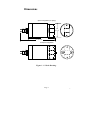
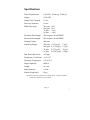
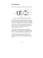
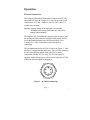
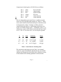
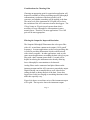
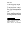
Seapoint
Chlorophyll
Fluorometer
User Manual
Standard Version
6/00
Dimensions
Open Configuration (no pump)
2.5"
(6.4 cm)
5.1" (13.0 cm)
6.6" (16.8 cm)
Pumped Configuration
Figure 1. 1/2 Scale Drawing.
Page 2
4/97
Specifications
Power Requirements:
8-20 VDC, 15mA avg, 27mA pk
Output:
0-5.0 VDC
Output Time Constant:
0.1 sec
Power-up Transient:
0.6 sec
RMS Noise (typ.):
30x gain:
10x gain:
3x gain:
1x gain:
Excitation Wavelength:
470 nm peak, 30 nm FBHM
Emission Wavelength:
685 nm peak, 30 nm FBHM
Sensing Volume:
340 mm3
Sensitivity/Range†:
30x gain:
10x gain:
3x gain:
1x gain:
Min. Detectable Level:
0.02 µg/l
3 mV
1 mV
<1 mV
<1 mV
1.0 V/(µg/l)
0.33 V/(µg/l)
0.1 V/(µg/l)
0.033V/(µg/l)
5 µg/l
15 µg/l
50 µg/l
150µg/l
Temperature Coefficient: < 0.2 %/°C
Operating Temperature:
0°C to 65°C
Depth Capability:
6000 m
Length:
16.8 cm
Body Diameter:
6.4 cm
Sensor Weight (dry):
850 g
†
Specified sensitivities and ranges are nominal values. Instrument should be
calibrated for quantitative measurements.
Page 3
4/97
Introduction
The Seapoint Chlorophyll Fluorometer is a high-performance,
low power instrument for in situ measurements of chlorophyll
a. Its small size, very low power consumption, high
sensitivity, wide dynamic range, 6000 meter depth capability,
and open or pump-through sample volume options provide the
power and flexibility to measure chlorophyll a in a wide
variety of conditions. The instrument has good ambient light
rejection and a low temperature coefficient.
The Seapoint Chlorophyll Fluorometer can be operated with
or without a pump. The small sensing volume of
approximately 340 mm3 can be left open to the surrounding
water, or, with the use of the supplied cap, can have water
drawn through it using a pump.
Two control lines allow the user to externally set the
sensitivity of the Seapoint Chlorophyll Fluorometer by
choosing one of four gains. This provides an easy means to
set the sensitivity to provide the range and resolution required
for a particular application. Sensitivities of 0.033, 0.1, 0.33,
and 1 V/(µg/l) are possible.
The Seapoint Chlorophyll Fluorometer is constructed of
rugged, corrosion-free materials, surface mount electronics,
and solid-state lamps and detector for excellent durability and
high reliability.
The Seapoint Chlorophyll Fluorometer uses the same Impulse
AG-206/306 connector as the Seapoint Turbidity Meter, and
the two instruments are pin-compatible.
Page 4
4/97
Optical Design
Figure 2 shows the Seapoint Chlorophyll Fluorometer optics.
Blue LED
Lenses
Excitation Filter/Window
Approximate Sensing Volume
Photodetector
Excitation Filter/Window
Emission Filter
Detector Window
Blue LED
Figure 2. Seapoint Chlorophyll Fluorometer Optics
The blue LED lamps direct light through the blue excitation
filter/windows illuminating the sensing volume. Chlorophyll
a present in the sensing volume is excited with the blue light
and fluoresces red light, a portion of which passes through the
detector window. This fluorescent light is then collimated
with a lens so that it passes through the emission filter nearly
normal to the filter. A second lens then focuses the
fluorescent light onto the detector.
The end plate of the instrument (or the cap in pumped
operation) prevents ambient light from reaching the detector
directly. The narrow bandwidth of the emission filter further
reduces the amount of ambient light reaching the detector.
The sensing volume of the instrument is defined by the
intersection of the lamp beams and the detector's cone of
reception. This volume is nearly a cylinder of approximately
340 mm3.
Page 5
4/97
Electronic Design
The Seapoint Chlorophyll Fluorometer has an electronic
design that achieves high sensitivity while consuming very
little power. Surface mount components are used for high
reliability and compact design. Low quiescent current
components are used, allowing all but about 3 milliamps of
the total current drawn by the instrument to drive the lamps.
Overall power requirements are 8-20 VDC, 15 mA average,
27 mA peak.
The instrument is very stable with temperature and time. The
LED lamps and the detector have low temperature coefficients
at their respective operating wavelengths. The overall
temperature coefficient of the instrument is less than 0.2%/°C.
Degradation of the lamps with operating time will result in
about 10% reduction in sensitivity after 5000 hours of
operation. Stable output of the instrument occurs at
approximately 0.6 seconds after power up.
The light source is modulated at 700 Hz and synchronous
detection is used to extract the fluorescent signal from the
unwanted portion of the signal resulting from ambient light
and electronic noise. Achieving high sensitivity using low
power was accomplished by paying careful attention to proper
circuit board layout to prevent any stray coupling of signals
synchronous with the modulation of the light source into the
detection circuitry. The offset voltage is proportional to the
selected gain.
Page 6
4/97
Operation
Electrical Connections
The Seapoint Chlorophyll Fluorometer requires 8 to 20 VDC
input and will draw an average of 15 mA current with a peak
current draw of 27 mA. Output is 0 to 5.0 VDC with a 0.1
second time constant.
Warning: Applying voltages to the output pin or powering the
instrument with a voltage greater than 20 V will result in
damage to the instrument.
The Impulse AG-306 bulkhead (connector end of sensor) and
the mating AG-206 connector (included with pigtail) should
be cleaned and lubricated with 3M Silicone Spray, Dow
Corning #111 Valve Lubricant or equivalent prior to
connecting.
The pin numbering on the AG-306 is shown in Figure 3. Note
that Pin 1 is larger than the other pins. The AG-206 connector
has two raised bumps which align with Pin 1 to make
connection with the AG-306 easy. The AG-206 pigtail is
supplied with a locking sleeve which screws onto the AG-306
connector after the pigtail is plugged in.
1
2
6
3
5
4
Figure 3. AG-306 Pin numbering.
Page 7
4/97
Connections for the Impulse AG-206/306 are as follows:
Pin 1
Pin 2
Pin 3
Pin 4
Pin 5
Pin 6
white:
black:
blue:
orange:
green:
red:
Power Ground
Signal Output
Signal Ground
Power In
Gain Control A
Gain Control B
The two independent gain control lines A and B are used to
select one of four possible gain settings (see Table 1). These
wires can be hardwired for the desired gain or interfaced with
a microprocessor, using 5 volt logic, to allow gain to be
controlled through software. Hardwiring the gain does not
require an external voltage source. To hardwire a line to +5V,
simply leave it open, which allows an internal pull-up to hold
it at +5 VDC. To set a line to 0V, tie it to the power ground.
A
B
Gain
Sensitivity
Range
+5 V
+5 V
30X
1 V/(µg/l)
5 µg/l
+5 V
0V
10X
0.33 V/(µg/l)
15 µg/l
0V
+5 V
3X
0.1 V/(µg/l)
50 µg/l
0V
0V
1X
0.033 V/(µg/l)
150 µg/l
Table 1. Truth Table for Switching Gains
The sensitivities and ranges given in Table 1 are nominal
values for a typical instrument, and therefore the user should
calibrate the instrument as described in the calibration section
of this manual before making quantitative measurements.
Page 8
4/97
Considerations for Choosing Gain
Choosing an appropriate gain for a particular application will
depend on a number of factors including expected chlorophyll
concentrations, resolution of the data recorder's A/D
converter, and whether smoothing will be applied to the data.
The noise level of the instrument at 30X gain will be above
the resolution of the A/D converters in most data loggers. The
150 µg/l range at 1X gain is much greater than what is
necessary to cover chlorophyll a concentrations in most
natural waters. Therefore, for most applications 3X or 10X
gain will be most appropriate.
Filtering the Output for Improved Resolution
The Seapoint Chlorophyll Fluorometer has a low-pass filter
with a 0.1 second time constant on its output (1.6 Hz cutoff
frequency). In some applications, such as ocean profiling, this
is useful in providing information which would be missed
with a slower response. In other applications, such as with
some moored applications, smoothing the data with a low-pass
filter with a time constant greater than 0.1 second will be
helpful in reducing the instrument noise thereby allowing
lower chlorophyll a concentrations to be detected.
Analog filters can be constructed and placed between the
instrument output and the A/D converter to smooth the output.
Digital filtering can accomplish this as well, either before
storing the data or during analysis of the data. Some data
loggers have built-in averaging or smoothing functions which
make this especially easy.
Figure 4(a) shows several time series of the instrument output
at 30x gain. The top series shows the instrument output
Page 9
4/97
without any external filtering. The underlying series show the
effects of applying low-pass analog filtering to the instrument
output. Frequency responses of the filters used are shown in
Figure 4(b).
Figure 5(a) shows more time series of the instrument output at
30x gain. The top series shows the instrument output sampled
at 0.11 second intervals. The underlying series were generated
by digitally filtering the series with moving averages, as
described by:
1
yn = N
N
✟ x i−k
k=0
Figure 5(b) shows the frequency responses of the moving
mean filters.
Page 10
4/97
10 mV/Division
None
RC=0.3 Sec.
RC=1.0 Sec.
RC=3.0 Sec.
0
100
200
300
400
500
Time (Seconds)
(a)
0
dB
RC=0.3 Sec.
RC=1.0 Sec.
-20
RC=3.0 Sec.
-40
0.01
0.1
1
10
Frequency (Hz)
(b)
Figure 4.
(a) Time series of fluorometer output at 30x gain
with and without low-pass analog filtering.
(b) Frequency response of single pole RC filter.
Page 11
4/97
Sample Interval = 0.11 sec
10 mV/Division
None
N=10
N=30
N=100
0
100
200
300
400
500
Time (Seconds)
(a)
0
N=30
N=10
dB
N=100
-20
-40
1
0.001
1000✁t
1
1
0.01
100✁t
0.1
10✁t
1
2✁t
1
Frequency
(b)
Figure 5. (a) Time series of fluorometer output at 30x gain with
and without digital filtering. (b) Frequency response of
moving average digital filter.
Page 12
4/97
Ambient Light Concerns
The combined optical filtering and synchronous detection give
the Seapoint Chlorophyll Fluorometer good ambient light
rejection, and ambient light will not be a concern when the
instrument is capped and operated with a pump. When
operating with an open sample volume, ambient light will not
contribute an offset to the output voltage of the instrument, but
strong fluctuating light may cause a noisy signal. This can
happen under fluorescent or incandescent lighting or in
surface waters in bright sunlight.
Laboratory lighting usually will not increase instrument noise
as long as the detector window faces down, away from the
lights. If the noisy output persists, shade the instrument or
perform tests or calibrations in a vessel with opaque walls.
If field measurements are to be made near the water surface
with an open sample volume, it is a good idea to experiment
with the instrument beforehand, and try to determine if the
noise caused by the ambient light will be significant. Again,
ambient light rejection will be best with the detector window
facing down. If the noise is indeed a concern, consider
constructing a baffle to shade the instrument.
Measurement Configurations
The Seapoint Chlorophyll Fluorometer may be configured for
open or pumped measurements of chlorophyll a in water.
Please note that the instrument is designed only for
measurements in water. Never immerse the instrument in
acetone solutions or pump acetone into the sensing volume,
which will result in damage to the instrument body and
windows.
Page 13
4/97
The Seapoint Chlorophyll Fluorometer is supplied in the open
sensing volume configuration. In this configuration, as the
surrounding water flows past the instrument, it will also flow
through the instrument's sensing volume
The Seapoint Chlorophyll Fluorometer also comes with a cap
which can be placed over the end of the instrument so that
water may be drawn through the instrument with a pump.
To install the cap, take off the end plate by removing the two
screws that hold it in place. Slip the large O-ring over the
lamp towers so that it rests on the reduced diameter of the
instrument body. Then slip the cap over the lamp towers so
that it presses the O-ring in place. Secure the cap with the two
screws which have small O-rings to prevent leaking. The cap
has nipples for 3/8" tubing. These nipples can be replaced to
accommodate other tubing sizes.
When using the instrument in pumped operation in the
laboratory, care should be taken to assure that air bubbles are
eliminated before making measurements. In this regard,
drawing water through the sample volume generally is more
effective that pushing it through with the pump.
Page 14
4/97
Calibration
The Seapoint Chlorophyll Fluorometer is adjusted at the
factory for the nominal range and sensitivity at a given gain
setting as specified in this manual. However, for accurate
quantitative measurements, user calibrations are required.
The Seapoint Chlorophyll Fluorometer is very stable, with
very little change in sensitivity over time. Nonetheless,
frequent calibration of the instrument is recommended. Some
decrease in sensitivity can be expected after extended use due
to decreased output of the lamps (about a 10% decrease in
output after 5000 hours of operation) and scratched window
surfaces.
Measurement of chlorophyll a and calibration of chlorophyll
fluorometers is somewhat inexact, and users not familiar with
calibration techniques and the considerations associated with
this subject are urged to consult with experts in this field or
refer to texts and papers for detailed discussion of these
matters1-4.
1. Parsons, T.R., Maita, Y. & Lalli, C.M. 1984. A Manual of Chemical and
Biological Methods for Sea Water Analysis, Permagon, Oxford, 173 pp.
2. Smith, R.C., Baker, K.S., and Dustan, P. 1981. Fluorometric Techniques for
the Measurement of Oceanic Chlorophyll in the Support of Remote Sensing,
Scripps Institution of Oceanography Ref. 81-17, 14 pp.
3. Mills, D.K. & Tett, P.B. 1990. "Use of a recording Fluorometer for continuous
measurement of phytoplankton concentration." Environment and Pollution
Measurement Sensors and Systems, SPIE Proc., 1269, 106-115.
4. Yentsch, C.M. & Yentsch, C.S. 1984. "Emergence of optical Instrumentation
for measuring biological properties." Oceanography and Marine Biology, an
Annual Review, 22, 55-98.
Page 15
4/97
Care
The Seapoint Chlorophyll Fluorometer is a rugged instrument
that should provide years of reliable performance with
minimal care.
After using, rinse the instrument and clean the windows with
water and mild detergent if necessary (avoid using organic
solvents). If the detector window becomes scratched, it may
be polished using a cloth buffing wheel with polishing
compound, or returned to Seapoint Sensors, Inc. for
refinishing or replacing.
The connectors should be lubricated before each use with 3M
silicone Spray, Dow Corning #111 Valve Lubricant or
equivalent.
The Seapoint Chlorophyll Fluorometer contains no user
serviceable electronics and must be returned to the factory if it
does not operate properly.
Limited Warranty
Seapoint Sensors, Inc. warrants this Chlorophyll Fluorometer to be free of defects
of materials and workmanship under normal use and service for a period of 1 year
from the date of shipment. This warranty extends only to the original purchaser.
In the event the product fails to operate according to our published specifications
during the warranty period, Seapoint Sensors, Inc. will repair or replace the
instrument at our discretion. If it is determined that the failure was due to other
than normal use or service, repairs will be billed and estimate will be submitted
prior to repair work.
Shipping costs must be prepaid. Seapoint Sensors, Inc. accepts no responsibility
for damage during return shipment.
Page 16
4/97
87 North Road
Kingston, NH
03848 -3056 USA
Tel: (603) 642-4921
Fax: (603) 642-4922
[email protected]