1
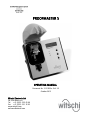
PROOFMASTER S OPERATING MANUAL Document No. 31.21D35e - Rel. 2.5 October 2012 Witschi Electronic Ltd CH-3294 Büren a.A. Tel. +41 (0)32 - 352 05 00 Fax +41 (0)32 - 351 32 92 www.witschi.com [email protected] Congratulations! You made the right choice. You bought PROOFMASTER S a test instrument answering to the highest technical standards while being easy to handle and operate. PROOFMASTER S has been especially designed for repair service centres, specialised trade outlets and for testing small series. Pre-set universal programs, custom-programmable test cycles and a friendly, menu-oriented approach, provide the highest possible ease of use and ensure that all watches will be reliably tested. Watches with or without wristlet can be tested. The special Leak Finder Program opens a new dimension in the hunt for watches leaks under water. The instrument, equipped with a USB interface, can be networked by using the optional WiCoTrace software. This manual helps operating PROOFMASTER S efficiently and adequately. It also provides important advice regarding safety and maintenance of the instrument. Always keep this manual ready to hand and pass it on to any new user. If properly handled and maintained, your new instrument will last for many years. Using it will be both enjoyable and cost-effective. Page 2/32 Witschi Electronic Ltd PROOFMASTER S is a powerful and accurate instrument for seal integrity testing of watches. The instrument must be exclusively used for its intended aims and purposes. PROOFMASTER S is manufactured according to the current state of the art and standard rules of safety technique. There remain however a number of residual risks, mostly due to inappropriate use or breach of the instructions provided in the user manual. The Manufacturer, Witschi Electronic Ltd. in CH-3294 BÜREN a.A., SWITZERLAND takes no responsibility whatsoever for damages due to inappropriate handling, such as damages to the test instrument, to watches and/or people. Tests with Proofmaster S are in general extremely reliable. The Witschi Electronic Ltd. Company does not however offer any warranty that a watch having successfully passed the test with PROOFMASTER S will be truly water-resistant when immersed in water. No responsibility will be taken for damages that can have been caused by the lack of waterresistance of a watch having been tested. Witschi Electronic Ltd Page 3/32 TABLE OF CONTENTS 1 INSTALLATION .............................................................................................................. 6 1.1 Scope of supply ........................................................................................................ 6 1.2 Location ................................................................................................................... 6 1.3 Mains connection ..................................................................................................... 6 1.4 Compressor .............................................................................................................. 6 1.5 Connecting the printer ............................................................................................. 8 1.6 Connection to a PC .................................................................................................. 8 2 OPERATION .................................................................................................................. 8 2.1 Switching on ............................................................................................................ 8 2.2 Program selection .................................................................................................. 10 2.3 Preset Programs ..................................................................................................... 11 2.4 Positioning the watch ............................................................................................ 11 2.5 Test ........................................................................................................................ 13 2.6 Interpretation of the results ................................................................................... 13 3 LEAKFINDER PROGRAM .............................................................................................. 14 3.1 How does the Leakfinder Program works? ............................................................. 14 3.2 Test sequence ........................................................................................................ 15 4 CUSTOMER-SPECIFIC PROGRAMS ................................................................................ 16 4.1 Procedure ............................................................................................................... 16 4.2 Test with one or two pressures .............................................................................. 17 4.3 Lower pressure ....................................................................................................... 17 4.4 Higher pressure ...................................................................................................... 17 4.5 Stabilisation time ................................................................................................... 18 4.6 Measuring time ...................................................................................................... 18 4.7 Tightness limits ...................................................................................................... 19 4.8 Case analysis.......................................................................................................... 19 4.9 Watch size.............................................................................................................. 19 4.10 Test mode .............................................................................................................. 20 4.11 Save parameters .................................................................................................... 20 5 SYSTEM PARAMETERS ................................................................................................ 20 5.1 Language selection ................................................................................................ 20 5.2 Display of the numerical results ............................................................................. 21 5.3 Date & Time ........................................................................................................... 21 5.4 Thermal Stabilization ? Yes / no ............................................................................. 21 5.5 Auto Print............................................................................................................... 21 5.6 Counter .................................................................................................................. 21 5.7 Identification number ............................................................................................. 21 5.8 Calibration date ..................................................................................................... 21 5.9 Calibration values .................................................................................................. 21 5.10 Programming the header ....................................................................................... 21 5.11 Default parameters ................................................................................................ 22 Page 4/32 Witschi Electronic Ltd 6 INFORMATION RELATED TO TESTING .......................................................................... 22 6.1 Measuring principle ................................................................................................ 22 6.2 Test sequence ......................................................................................................... 22 6.3 Deformation ........................................................................................................... 24 6.4 Leak rate ................................................................................................................ 24 6.5 Tolerance limit ........................................................................................................ 25 6.6 Reference to ISO Standard ...................................................................................... 25 6.7 Measurement resolution (precision) ....................................................................... 26 6.8 Detrimental Factors in Test ..................................................................................... 27 7 Faulty Operation ......................................................................................................... 28 7.1 Error messages ....................................................................................................... 28 7.2 Emergency release .................................................................................................. 29 8 MAINTENANCE AND CALIBRATION ............................................................................. 29 8.1 Proofmaster S ......................................................................................................... 29 8.2 Compressor JunAir.................................................................................................. 29 9 DISPOSAL OF THE INSTRUMENT .................................................................................. 30 10 TECHNICAL DATA ....................................................................................................... 30 11 EC DECLARATION OF CONFORMITY ....................................................................... 32 Witschi Electronic Ltd Page 5/32 1 INSTALLATION 1.1 SCOPE OF SUPPLY • Testing instrument PROOFMASTER S. • Compressed-air hose Ø 6 - 4 mm with plug nipple. • Set of 3 carriers for watches. • Mains adapter 9 V~, 1.2 A, optionally for 230 V~ or 120 V ~. • Dust protection cover. • UBS Cable for connection to a PC. • Operating Manual. 1.2 LOCATION A reliable test requires the instrument to be at the ambient temperature. Thus, the instrument should not be placed close to heaters, open windows or exposed to the sun. 1.3 MAINS CONNECTION A mains adapter supplies PROOFMASTER S with a 9 V~ output alternating voltage and a maximum current of 1.2 A. The mains adapter is available for a mains voltage of 230 V~ (range 210 V~ – 240 V~) or for a mains voltage of 120 V~ (range 110 V~ – 130 V~). Before connecting for the first time, ensure that the voltage of the mains adapter corresponds to the voltage of your mains. Only use the original mains adapter. Connect the mains adapter to the 9V~ 1.2A socket on the rear panel of the instrument. We recommend disconnecting the mains adapter from the mains during longer idle periods, e.g. vacations. 1.4 COMPRESSOR PROOFMASTER S only needs compressed air for operating since a vacuum generation device is already included. The instrument can be connected to various compressed air sources. To benefit from the entire pressure range of PROOFMASTER S, it is necessary to dispose of a compressor with an output pressure of 11 bar. Since standard compressors only provide a pressure of 6 bar, we recommend using our special JunAir 6-M compressor instead. Page 6/32 Witschi Electronic Ltd Kindly never fail to pay attention to the following important points: • Only use oil-free, dry and dust-free air (use a filter). • The lowest input pressure must exceed the working test pressure used by at least 1.0 bar. • For the vacuum test, the compressor must include a pressure vessel with a volume of at least 4 litre. • Before connecting to the mains, ensure that the voltage of the compressor corresponds to the voltage of your mains. • A PROOFMASTER S can be damaged if condensation water penetrates the instrument together with the compressed air. Therefore, carry out a regular maintenance of the compressor and air filte (see Chapter 8.2 Compressor JunAir). 57H • Maximum input pressure 12 bar (set pressure reducing valve on compressor to 11 bar). • The sudden discharge of compressed air can cause injuries. Exercise care when manipulating the compressor and the compressed-air hoses. • Before a possible disassembly of parts of the instrument, disconnect it from the compressor. Never open pressurised parts of the instrument using force. • Normal pneumatic instruments and fittings are appropriate for a maximum pressure of 8 bar. They may not be connected to the compressed-air supply of 11 bar. Compressed-air connection Introduce the open end of the flexible tube up to the catch into the plug-in coupling labelled max. 12bar. To unplug the compressed air tube, press the black ring of the plug-in coupling toward the rear panel of the instrument. Simultaneously unplug the tube. Only unplug the tube when it is not under pressure. Remove the fast coupling from the compressor before unplugging the tube. The supplied compressor is equipped with a safety coupling compatible with the connecting tube of the PROOFMASTER S. Plug in the extremity of the tube with the plug-in nipple into the safety coupling of the compressor. To unplug the plug-in nipple, first shift back the black sleeve of the coupling (pressure relief), and then forward (release). Witschi Electronic Ltd Page 7/32 1.5 CONNECTING THE PRINTER The printer interface for connecting the optional printer with the supplied connecting cable is located on the rear panel of the instrument. The results can also be printed with the printer of a PC by connecting this PC to the printer interface. This requires the Auto Print software available as an option with the suitable RS cable. 1.6 CONNECTION TO A PC The instrument can be connected to a PC with the USB interface on the rear panel. The transfer of results to the PC and their evaluation requires the Proofmaster M/S software available as an option. 2 OPERATION 2.1 SWITCHING ON Switch on the instrument with the I / O switch on the rear side of the instrument. The following display briefly appears for approximately 3 seconds: Witschi Electronic Proofmaster S V1.xx Calibration date: 19.01.2011 Instrument name xx = number of the installed firmware version. Last calibration date. The locking mechanism opens at the same time and the test chamber is lifted. After this, the program which was selected prior to the last time the instrument was switched off, will be activated. To change the display language to the one you want, select another language according to chapter 5.1 Language selection, page . Page 8/32 Witschi Electronic Ltd Operating Elements and Display The operating elements on the front panel offer the following functions: • print Press this button to print current test results, measurement and system parameters, if the optionally available printer is connected. • escape • select Press this button to stop a running test. From a special test program this takes you back to the program F1 Safe Test. Back to main menu, if you edit a program. By pressing the cursor button down or up, you select a test program or change a selected parameter. By pressing the cursor button to the left or right you select a parameter in the programming mode and the Leakfinder program in test and result mode. • enter By pressing the cursor button vertically you confirm the selection and continue to the next input step. The PROOFMASTER S is equipped with an illuminated LCD display with 4x20 characters. The instrument communicates in 9 different languages (see Chapter 5.1 Language selection, page 20). • Before the start of a test the selected test program with the relevant parameters is displayed. • You will receive information concerning the test progress during the test. • At the end of the test, the results as well as the date and time are displayed. Witschi Electronic Ltd Page 9/32 In addition, the 3 light-emitting diodes inform you about the status of the test. The functions of the 3 LED's are: • signal Glows yellow as soon as the sensor has been correctly lowered onto the watch. • I Test 1 good (green), poor (red) or uncertain (yellow). • II Test 2 good (green), poor (red) or uncertain (yellow). 2.2 PROGRAM SELECTION With the PROOFMASTER S you can select the optimum test program for testing a certain watch from 18 different programs. The programs P1 to P8 are predefined programs whose parameters are optimised for different watch types. These programs cannot be changed. In the case of the customer-specific programs C01 to C10 you may determine the parameters in accordance with your requirements. Select the desired program by pressing the cursor button up or down several times. Press escape, if the instrument is not on the menu level for the program selection (e.g. on the menu level result display or parameter programming). P1 - Safe Test Test 1 -0.2 bar Test 2 + 2.0 bar The number and the program name are displayed in the first line. The two test pressures are displayed in the second and third lines. Select: ↑↓ Too high test pressure or vacuum can damage the watch being tested! Page 10/32 Witschi Electronic Ltd 2.3 PRESET PROGRAMS P1 - Safe Test Test 1 - 0.2 bar Test 2 + 2.0 bar This program can be used with all types of water-resistant watches without risk of damages. This programme gives unreliable results with hard watches. P2 - Men Standard Test 1 - 0.4 bar Test 2 + 3.0 bar Standard program for gent’s watches, plastic or metal. P3 - Ladies Test 1 - 0.4 bar Test 2 + 2.0 bar Program for small watches (lady’s watches). P4 - Hard Case Test 1 - 0.7 bar Test 2 + 3.0 bar For hard, stable watches with ceramic case and mineral glass. P5 – Jewelery Test 1 - 0.2 bar Test 2 + 1.0 bar For jewellery watches and other watches with less stable cases. P6 – Diver 100m Test 1 - 0.7 bar Test 2 + 10.0 bar Threefold test for diver watches that are specified for at least 100 m water depth. P7 – Pressure only Test 1 + 2.0 bar Pressure only, for quick tests. P8 - Two pressures Test 1 + 0.5 bar Test 2 + 3.0 bar 1 low pressure and a higher pressure (double pressure test). For watches that should not be vacuum tested. P9 – Altimeter Prg1 Test 1 + 0.5 bar Special program "Altimeter" with delayed and gentle "Step by Step" pressure increase and pressure decrease. Specially designed for watches with integrated altimeter and pressure sensors. P10 – Altimeter Prg2 Test 1 + 0.5 bar Test 2 + 3.0 bar Special program "Altimeter" with delayed and gentle "Step by Step" pressure increase and pressure decrease. Specially designed for watches with integrated altimeter and pressure sensors. C01 – C11 Test programs adaptable to your requirements. See Chapter 4 CUSTOMER - SPECIFIC PROGRAMS 60H 2.4 POSITIONING THE WATCH The watch must be at ambient temperature for the test to be reliable. Results can be invalidated by variations in the watch temperature during the test. Test results can be invalidated by adhesive protection on the bottom or on the glass of the watch. Witschi Electronic Ltd Page 11/32 Lift the sensor with knob A. When lifting the knob, the sensor is unlocked and can be freely moved up and down. Place the watch on the three-point support of the support table. Check that the watch lies horizontally. If the bottom of the watch is not flat (battery case), it may be better to place the watch with the glass looking downward. Wristlet should be placed on the three-point support in such a way that the watch is in a stable position. A Move the sensor at the knob A slowly downward, until it rests upon the watch. The sensor must rest upon the watch through its own weight. When releasing the knob, the sensor is blocked. The signal LED lights up when the sensor is correctly lowered. Page 12/32 Witschi Electronic Ltd 2.5 TEST Once you have positioned the watch press the test chamber down until it locks. The test sequence starts automatically. The test sequence consists of the following steps: • • • • • • • Filling up the first test pressure Stabilising Measurement Filling up the second test pressure Stabilising Measurement Pressure release The test sequence can be followed on the PROOFMASTER S display. P1 Test 1 - 0.205 bar Measure 77 s Deformation +2.0% -0.04µ The program number, the current test and the current test pressure are displayed in the first line. The second line shows the status of the test (stabilising, measuring) and the remaining maximum time to the end of the current test step. During stabilisation, the current deformation is displayed in the third line. During the measurement, the current change of the deformation in % and in µm is displayed. Test 1 okay +0.4% At the end of the measurement, the results and the good/poor evaluation are displayed. Date and time are displayed in the last line. Test 2 okay +0.2% At the end of the test, the test chamber opens automatically. P1 – 0.2 / + 2.0 bar 21.01.2011 09. 16 Move the sensor up with knob A and remove the watch. Comprehensive information concerning the test procedure is described in Chapter 6.2. Test sequence, page 22. 2.6 INTERPRETATION OF THE RESULTS The possible results of a test are listed in the following. Big leakage or not Compressible watch Leakfinder:→← 14. 23 Once the pressure has been applied, the deformation is less than the minimum value which is determined by the instrument based on the test parameters. The watch either has a large leak, which causes an instantaneous pressure equalisation or the watch is so rigid that it can be sufficiently compressed with the selected pressure. With the Leakfinder Program you can locate a possible leak (see Chapter 3 LEAKFINDER PROGRAM, page 13). Witschi Electronic Ltd Page 13/32 Important leakage detected Leakfinder:→← P1 10. 58 – 0.2 / + 2.0 bar Test 1 poor -5.2% Test 2 poor -12.5% Leakfinder:→← 11. 10 P1 The watch is leaking. The size of the leak has exceeded the numerical measuring range of the PROOFMASTER S. With the Leakfinder Program you may locate the leak. The deformation reversal with both pressures is greater than the set leak-proof limit, the watch is leaky. With the Leakfinder Program you may locate the leak. – 0.2 / + 2.0 bar Test 1 okay +0.4% Test 2 okay +0.2% 21.01.2011 11. 18 The deformation reversal is less than the programmed leakproof limits or the watch shows a low increase of the deformation, the watch does not leak. With the C01 C10 test programs a fixed measuring time may also be programmed instead of the automatic measuring time. If the programmed, fixed measuring time is too short the result becomes uncertain. This is indicated by a question mark next to the result and by a good/poor display illuminated yellow. In this case we recommend increasing the measuring time or setting to Aut. Leakage rate If the measurement is within the numerical measuring range a positive or negative percentage value appears next to the good/poor display as a result in the display at the end of the test. This value represents the percentage change of the deformation during the measurement. The value is converted to a measuring time of 60s. The display of the numerical results may be switched on or switched off; see Chapter 5.2 Display of numerical results. 62H Additional information relating to the leakage rate may be found in Chapter 6.4 Leakage rate. 63H 3 LEAKFINDER PROGRAM PROOFMASTER S is the first instrument of its kind worldwide with the so-called Leakfinder program developed by Witschi Electronic. This program conditions a watch that isn’t water-resistant for locating the leak under water. 3.1 HOW DOES THE LEAKFINDER PROGRAM WORKS? The watch is set under pressure for a significant amount of time. Let us suppose that the watch is not water-resistant. In this case, the air penetrating into it causes an excess pressure. Page 14/32 Witschi Electronic Ltd When the watch isn’t under pressure anymore, the incoming air escapes again through the leak. Bubbles arising when the watch is under water indicate the position of the leak. In the case of a small to medium leak, it takes several minutes until the excess pressure has been released. Thus, a short test under water does not present any risk that water penetrates into the watch. If the leak is very big however, the excess pressure is released faster and there is some risk that water penetrates into the watch. PROOFMASTER S measures the size of the leak with the Leakfinder Program and indicates to you if the watch can be immersed in water without risk. Based on the size of the leak and the selected pressure, the instrument computes the time during which the pressure has to be applied to the watch to create a high enough excess pressure in it. Note: Certain leaks due to a deformation of the case only manifest themselves at higher pressure and close again when the watch is under a normal pressure environment. Such leaks cannot be located with the water test. 3.2 TEST SEQUENCE Selecting the Leakfinder Program The Proofmaster S has two possibilities for selecting and using the Leakfinder Program: The information for using the Leakfinder Program automatically appears on the display once a watch has completed the previous test with a poor result (leaking). The customer now has the choice to prepare the watch for locating the leakage in water by means of the Leakfinder Program or not. Leak Finder Progam Type: Stnd Case Time: Auto Pr: + 2.0 bar Start>> Locking the chamber The Leakfinder Program may be used as an independent test unrelated to other programs, i.e. without previous test in another test program. The Leakfinder Program is selected by pushing the cursor to the left or to the right. Selection of parameters When selecting the Leakfinder Program the following parameters are automatically set • Type: The case type is automatically taken over from the test program previously used. • Time: This parameter is set on Auto by default. The time needed is automatically determined based on the leak size. We recommend using Auto for a riskless water test. You can set here the time during the watch will be under pressure from 60 to 600 s and Auto. • Pr: Normally, the pressure is taken over from the program previously used. It is also possible to enter another pressure. Test sequence If the watch has not already been placed on the sensor, put it in position and lower the sensor. Select the Leakfinder Program and close the chamber. The watch check and preparation for the water test runs down. Depending on the size of the leak, this can take up to 10 minutes. Witschi Electronic Ltd Page 15/32 One of the messages below appears at the end of the test: BIG LEAKAGE WATER TEST IMPOSSIBLE The watch leak is too big. The watch must not be immersed in water. In the case of a very big leak, this message is displayed before the end of the check. NO OR SMALL LEAK CONTINUE WATER TEST You can immerse the watch for the water test. Water test Extract immediately the watch from the instrument and place it in a transparent receptacle filled with water. If the watch has a leak, bubbles appear at the position of the leak. If the leak is small, the bubbles form very slowly. It may take several minutes to identify the position of the leak. If possible, use distilled water for the test. It avoids the formation of limestone deposits on the watch. Remove the watch from the water if the formation of bubbles slows down in the case of a bigger leak. Water might penetrate into the watch if the excess pressure in the watch has entirely vanished. 4 CUSTOMER-SPECIFIC PROGRAMS The customer-specific programs C01 to C11 can be adapted according to your own needs, to take into account the specific characteristics of your watches. The next chapters provide you with hints for programming the test sequence and selecting the parameters. C11 is a special program "Altimeter" with delayed and gentle "Step by Step" pressure increase and pressure decrease. Specially designed for watches with integrated altimeter and pressure sensors. 4.1 PROCEDURE • Select one of the programs C01 – C10 by pressing the cursor button up or down. • Press enter to edit the parameters. • Press the cursor button to the left or right to select the desired parameter. Page 16/32 Witschi Electronic Ltd • Press the cursor button up or down to change the parameter value. • Press the cursor button to the right to get to the next parameter. • Press escape to leave the Editing menu. Note: The changed parameters are only stored if you have selected Save parameters yes (last point in Editing menu) and confirmed with enter. 4.2 TEST WITH ONE OR TWO PRESSURES CO1 Test with ( 1/2 ) Pressures 2 Change: ↑↓ Param:← → Quit: esc In the case of a vacuum test, the bottom of the case and the glass show a tendency to be lifted. This provides a way to detect certain faults that are not coming to light under a pressure strain. Let us mention e.g. insufficient pressure of the case bottom or of the battery cover on the O-ring. Therefore, to obtain an exhaustive test, we recommend performing one vacuum test and one pressure test 4.3 LOWER PRESSURE CO1 Lower pressure Vacuum bar: -0.2 Change: ↑↓ Param:← → Quit: esc uum not exceeding -0.3 bar. The first test is normally performed with vacuum. You can also select a lower pressure instead of vacuum if it better fits the characteristics of the watch. Proceed with care when testing jewellery watches and very flat watches with vacuum! Vacuum could crack the bottom or the glass. We advise you to test such watches with a vac- Robust watches, in particular watches with a hard case (diver watches) must be tested with a vacuum between -0.5 to -0.7 bar. The resulting deformation is large enough for a fast and reliable test. The vacuum generator can provide a vacuum up to 85% of the normal pressure environment. Therefore, it is impossible to generate the maximum vacuum of -0.8 bar at high altitude. The table below indicates the highest possible vacuum values: Altitude Maximum vacuum 0m -0.85 bar 500 m -0.81 bar 1000 m -0.76 bar 1500 m -0.72 bar 2000m -0.68 bar 4.4 HIGHER PRESSURE CO1 Higher pressure +0.2 – 10 bar? Change: ↑↓ + 2.0 Param:← → The second test pressure must be higher than the first one. For the last test, we recommend testing at the highest pressure admissible for this watch Quit: esc So-called water-resistant wristwatches should (according to the corresponding standard) be tested at a pressure not exceeding 2 bar. Witschi Electronic Ltd Page 17/32 Watches wearing a label for the maximal pressure or the maximal water depth can be tested up to this pressure (10 m water depth = 1 bar pressure). WATER RESISTANT 30M Do not test the watch at too high a pressure. The plastic case of a watch, in particular, can be so heavily compressed that the movement will be damaged. The table below indicates the internal (Vacuum) and external (Pressure) forces acting on the glass and bottom of the watch case. Vacuum Watch size Pressure -0.2bar -0.4bar -0.7bar 1bar 2bar 0.6kg 1.2kg 2.0kg 1.3kg 2.5kg 4.1kg 2.2kg 4.3kg 7.1kg 3.2kg 6.2kg 10.2kg 6.3kg 12.3kg 20.4kg Glass/ Bottom Ø 20 mm Glass/ Bottom Ø 28 mm Glass/ Bottom Ø 36 mm 5bar 10bar 15.7kg 30.8kg 50.9kg 31.4kg 61.6kg 101.8kg 4.5 STABILISATION TIME CO1 Stabilis. time 15 – 600s/Auts? Change: ↑↓ Auts Param:← → Quit: esc The deformation of the watch still shows some increase after the pressure has been applied (plastic deformation). It is therefore necessary to wait for a certain time before the actual measure can start. We recommend using the Aut s mode. In this case, the shortest measuring time needed is automatically determined according to the behaviour of the watch. 4.6 MEASURING TIME CO1 Measuring time 15 – 600s/Auts? Change: ↑↓ Auts Param:← → Quit: esc Page 18/32 The time needed for a reliable measurement depends on the measured deformation and the programmed water-resistance limit. We recommend using the Aut s mode. In this case, the shortest measuring time needed is automatically determined according to the measurement parameters and the deformation of the watch. Witschi Electronic Ltd 4.7 TIGHTNESS LIMITS CO1 Tightness limits Standard % min Change: ↑↓ - 1.0 Param:← → Quit: esc Allows entering the water-resistance limit in % per minute based on a 2 bar test pressure. If the programmed test pressure is different from 2 bar, the instrument automatically converts the limit based on the test pressure. For a test in accordance with the ISO standard, the water-resistance limit must be adapted to the free volume in the watch. We recommend using the following values: • -0.5% for large watches • -1% for medium watches (Standard value) • -2% for small watches 4.8 CASE ANALYSIS Soft/Stnd/Hard? Stnd To determine the minimum necessary deformation, the Proofmaster needs the information about the ductility of the watch case. Change: ↑↓ This parameter affects "Big leakage". CO1 Case analysis Param:← → Quit: esc You can select one of the following case types: • Soft for plastic cases and thin-walled metal cases. • Stnd for normal and robust watches with metal case. • Hard for watches with hard case (hard metal, ceramics) and for diver watches. 4.9 WATCH SIZE CO1 Watch size Ø (mm) 20-40 mm Change: ↑↓ Param:← → Quit: esc In the case of the watch size, the dimensions refer to the glass or bottom diameter. To determine the minimum necessary deformation, the Proofmaster S needs the information the watch size. You can select from the following watch sizes: • Smaller than 20 mm • 20 – 40 mm • Larger than 40 mm Witschi Electronic Ltd Page 19/32 4.10 TEST MODE CO1 Test mode Lab/Stnd/Prod? MStnd Change: ↑↓ Param:← → Quit: esc Proofmaster S offers 3 different modes for the measurement accuracy The greater the measurement accuracy is selected, the longer are the measuring times. LAB: Very accurate measurement with long measurement time intervals for lab experiments and tests. Corresponds to a 5% resolution of the set water-resistance limit. STND: Normal test mode with adequate accuracy for a reliable measurement. Corresponds to a 25% resolution of the set water-resistance limit. PROD: Accelerated test mode for the production with a somewhat reduced accuracy. Corresponds to a 40% resolution of the set water-resistance limit. Take into account the fact that the measurement accuracy and reproducibility reached in practice primarily depend on the behaviour of the watch under the test conditions and not on the accuracy limits of PROOFMASTER S. CO1 Save parameters Yes / No? Yes Change: ↑↓ Param:← → Save: ← I 4.11 SAVE PARAMETERS Select Save param. and acknowledge with Yes if you want to store the modified parameter. If the parameters are not stored these are only active for as long as the relevant program is selected. 5 SYSTEM PARAMETERS The instrument can be configured to meet your requirements with the System parameters menu. This menu also provides important information concerning your instrument. To access the menu, hold the cursor button (enter) pressed down (approx. 4 s) when switching on the instrument, until the setting Change language appears on the display. By pressing the cursor button up or down, you can select the desired value from the available parameter values. In some settings you can choose between Yes and No. Change language *English* Change: ↑↓ Param:← → Quit: esc By pressing the button to the right or by pressing enter you get to the next parameter in the menu System parameters. At the end you return to the main menu. You may also return to the main menu at any time by pressing the escape button. 5.1 LANGUAGE SELECTION You can select one of the following languages: D A N S K , D E U T S C H , E N G L I S H, E S P A N O L, F R A N C A I S, I T A L I A N O, N O R S K, S U O M I, S V E N S K A Page 20/32 Witschi Electronic Ltd 5.2 DISPLAY OF THE NUMERICAL RESULTS You can select if the numerical results should be displayed and printed out in addition to the good/poor evaluation. 5.3 DATE & TIME By pressing the cursor button up or down you set the date (day). By pressing enter you go to the month setting – to the year setting and then to the time setting. 5.4 THERMAL STABILIZATION ? YES / NO (Default setting: No). Once the watch is stable, the test cycle starts automatically. The stabilization period is limited to max. 255 seconds. The activation of this parameter is only useful, if worn wrist watches are tested which have not yet stabilized at ambient temperature, and could falsify the test results. This is the case, if for example a watch is tested before it has cooled down to the ambient temperature. Plastic watches are particulary sensitive. 5.5 AUTO PRINT You can select if after each test, the results are printed out automatically or only by pressing the print button. The standard setting is AutoPrint no. 5.6 COUNTER Counter for the measurement cycles that have been carried out. Can not be reset to to 0. 5.7 IDENTIFICATION NUMBER Serial number of the instrument. Set by the Witschi Company. 5.8 CALIBRATION DATE Last calibration date. Set by our calibration service. 5.9 CALIBRATION VALUES With the next 3 menu points the values of the last calibration are displayed which are of interest to our calibration service. 5.10 PROGRAMMING THE HEADER Witschi Electronic CH-3294 Bueren a.A. Change: ↑↓ Param:← → Save: ← I The header for the printout of the results may be programmed according to your desires. Upon delivery of the instrument, the following header is programmed: The selected character flashes. Press the cursor button down and up to change the character. Press enter to move the cursor to the next character which you can change as the previous one etc. Once you have entered your header (max. 2 x 20 characters) press the cursor button to the right to get to the next parameter. Witschi Electronic Ltd Page 21/32 5.11 DEFAULT PARAMETERS Allows resetting all modified parameters to their default values. Caution! All customer programs are reset to their initial values. 6 INFORMATION RELATED TO TESTING 6.1 MEASURING PRINCIPLE PROOFMASTER S tests the seal integrity of watches according to the deformation principle. The watch to be tested is fixed in a very sensitive path-measuring system that continuously measures and monitors the changes in the deformation of the watch. The watch is submitted to a pressure or a vacuum after the measuring chamber has been closed. This causes the watch to undergo some contraction or expansion. This deformation stays constant as long as a constant pressure is applied if the watch is leak tight. If the watch is not leak tight, the air flowing into the watchcase or out of it causes a pressure equalisation that reverses the deformation. The speed of the deformation reversal depends on the leak size. 6.2 TEST SEQUENCE Locking After the chamber is closed manually, it is automatically locked. Initial value of the deformation The initial value of the deformation is measured after the chamber has been closed. This value constitutes the zero of the deformation measurement. Pressure build-up The first test pressure (usually vacuum) builds up in the test chamber after the zero of the deformation has been determined. Big leakage / Important leakage Big leakage If no significant deformation is observed following a pressure build-up, this means in general that the watch has a big leak that causes an immediate pressure equalisation. In this case, the test is aborted. The limit depends on the measurement parameters and is displayed during the stabilisation process. Important leakage The test is also aborted if the leakage exceeds the range detectable by the instrument. Page 22/32 Witschi Electronic Ltd Stabilisation Most watches show a more or less distinctive plastic behaviour. In other terms, the deformation still increases somewhat after the application of the pressure and needs a certain time to reach a stable final state. The increase of the deformation can mask a small leakage. Therefore, accurate measurement cannot be performed during this time. The stabilisation time ends automatically when the deformation is stable enough for allowing accurate measurements to take place. The limit depends on the programmed watch characteristics and on the test pressure. Measurement PROOFMASTER S automatically computes the shortest measuring time needed for a reliable measurement. When the measurement process is started, the last deformation value is stored as the zero. The variation relative to this initial value is continuously evaluated during the measurement process. Should a watch not be leak tight, the measurement process will be terminated as soon as a deformation reversal corresponding to the water-resistance criterion is detected. The measurement is automatically repeated if the instrument does not reach an unambiguous result. In such a case, Repeat appears on the display for a few seconds. The percent modification of the deformation converted to a measuring time of 60 s and the pass/fail evaluation are displayed at the end of the measurement process. Test at the next pressure The test with the first pressure value is followed by a test with the second pressure value according to the sequence described above. Pressure release, chamber opening The test releases the pressure after normal or abnormal termination. If a bigger leak has been detected during a test, the pressure will be lowered gradually and slowly to reduce an excess pressure inside the watch that could damage it. Once the pressure has been released, t the chamber is automatically opened. Witschi Electronic Ltd Page 23/32 6.3 DEFORMATION With every PROOFMASTER S test, one must keep in mind the fact that the measured deformations are extremely small and that even minimal influences can alter the measurements. For instance: A stable watch (diver watch) undergoes a deformation of about 3 µm (3 thousandth parts of a millimetre) under a pressure of 0.5 bar. This watch will be rejected as bad if the deformation has regressed by more than 0.06 µm (0.06 thousandth parts of a millimetre) after one minute. The more stable the watch being tested and the smaller the selected test pressure, therefore the smaller the deformation and the trickier the measurement. Therefore, a fast and reliable measurement always requires the highest possible pressure or vacuum. 6.4 LEAK RATE PROOFMASTER S computes the deformation reversal as a percentage of the initial deformation based on a measuring time of 1 minute. The percentage deformation reversal for a given leak size depends on the test pressure. The result is ever converted in accordance to test pressure; see table in chapter 6.6 Negative percentage A negative percentage indicates that the deformation has been reversed during the measuring time. This means in general that the watch is not leak tight. The higher the percentage, the bigger the leakage. In the case of a vacuum test, a negative percentage is also obtained if the watch is cooling down during the test. In other terms, it may occur if the temperature of the watch exceeds the ambient temperature at the beginning of the test. The watch is classed as not leak tight if the negative value exceeds the programmed waterresistance limit. Positive percentage A positive percentage means that the deformation has still shown a small increase after the stabilisation time. The deformation of a water-resistant watch with plastic behaviour still increases slightly during the measuring time and the result will be a positive value. Small positive values for the deformation do not affect the reliability of the measurement process. A significant increase of the deformation during the measurement process could however mask a small leak and compromise the measurements. PROOFMASTER S monitors the variations of the deformation during the stabilisation time and only starts the measurement process when it has become reliable. Page 24/32 Witschi Electronic Ltd 6.5 TOLERANCE LIMIT The programmed tolerance limit refers to the standard 2 bar test pressure. If the test pressure is not 2 bar, the result is converted accordingly (see next chapter). The default value is -1%/min for medium-sized watches and -2%/min for small watches (based on 2 bar). The value for customer-specific programs can be selected between -0.1% and -3.0%. The lower the selected water-resistance limit, the longer the measuring time intervals needed for an accurate measurement. 6.6 REFERENCE TO ISO STANDARD The ISO 22810 Standard states that a watch is to be considered as water-resistant if less than 50 µg of air per minute penetrates into the watch at a test pressure of 2 bar. A leak test based on the deformation principle does not allow the weight of the inflowing air to be directly measured. Under specific assumptions, it is however possible to establish a relation between the weight of the inflowing air and the deformation reversal. With a medium-size wristwatch (free volume in the watch: 2140 mm3) and a test pressure of 2 bar, a flow of 50 µg of air per minute correspond to a deformation reversal of 1% per minute. This value is set as the water-resistance limit in the pre-set programs. The ISO 22810 standard does not take into account the volume of the watch. Therefore, the leak rate value of 50 µg per min is valid for all watches irrespective of their size. In the test according to the deformation principle (PROOFMASTER S), the deformation reversal depends on the free volume in the watch. A watch with a smaller volume shows a greater deformation reversal for the same quantity of inflowing air. For a test in accordance with the standard, it is necessary to program the water-resistance limit according to the free volume in the watch. The approximate values are -0.5% for large watches, -1% for medium watches and -2% for small watches. The standard refers to a pressure of 2 bar, respectively 0.5 bar. Limits for other pressure values are not specified. Let us assume that the limit of 50 µg per minute is valid for all test pressure values. The water-resistance limit set for a pressure of 2 bar is hence adjusted as a function of the test pressure that corresponds to the 50 µg per minute limit. Witschi Electronic Ltd Page 25/32 For the standard limit of 1% the following limits result as a function of the pressure: (see following table, 1st and 2nd column). So that the indicated result [%/min] is suitable with the adjusted limit, the result is computed with a factor and then displayed (3rd column). Pressure [bar] Limit [%/min] Calculation displayed result [%/min] 0.5 -4 Test result *0.25 1 -2 Test result *0.5 2 -1 Test result *1 5 -0.4 Test result *2.5 10 -0.2 Test result *5 Example: With a pressure of 5 bar the adjusted limit of -1%/min is, related to 2 bar test pressure, for the measurement reduced to -0.4%/min. Therefore the displayed result is: -1.25%/min (table, column 1 and 3; row 4). The corresponding limit adapted to the pressure is shown on the display during the test. Note: As explained above, the leak test can be performed with PROOFMASTER S according to the ISO standard with results being in good agreement. However, since the test principle of PROOFMASTER S does not correspond to the ISO 22810 standard, it is not possible to ensure 100% conformity. 6.7 MEASUREMENT RESOLUTION (PRECISION) The measurement resolution determines the smallest measurable unit for deformation reversal. With PROOFMASTER S, the measurement resolution is determined by the programmed waterresistance limit and the selected test mode (Lab, Stnd, Prod, see Chapter 4.7 Tightness limits, page 19). With the pre-set programs, the instrument measures with a 25% resolution of the waterresistance limit, i.e. 4 times more accurately than the programmed tolerance limit. The higher the measurement resolution, the more accurate the measured leak rate with correspondingly longer measuring times. The value for customer-specific programs can be selected between 5% (Labo), 25% (Stnd) and 40% (Prod) measurement resolution values. Page 26/32 Witschi Electronic Ltd 6.8 DETRIMENTAL FACTORS IN TEST • Badly positioned watch. The watch, when it is tested, must be in a stable position on all three supporting points of the support table. It is for instance impossible to carry out a reliable test if one side of the watch rests on the wristlet. Indeed, the band undergoes an unpredictable deformation during the measurement process. The wristlet must be removed if necessary. If the size or the unsuitable shape of the watch prevents it to be placed correctly, use one of the three supplied supports. It is often difficult to position watches with a protruding battery case. It may be better to place the watch with the glass looking downward. • Adhesive label or protecting foil on the bottom of the case. An adhesive label on the bottom of the case causes a strong plastic deformation during the test since the adhesive layer is slowly pushed in by the pressure of the support points. This effect can simulate a leak with vacuum testing. It can hide a small leak with pressure testing. Therefore, any label and protecting foil must be removed prior to testing. A thin protecting lacquer applied to the bottom of the case usually doesn’t have any significant influence on the test. • The watch temperature and the ambient temperature differ. A watch cooling down or warming undergoes a deformation in a completely unpredictable way. This may completely alter measurement results. Therefore, a watch that has been worn on the wrist cannot be tested immediately. To carry out reliable tests, we recommend lying the watches to be tested for at least an hour near the test instrument, so that they can reach ambient temperature. The PROOFMASTER S too must be at ambient temperature when testing. Thus, the instrument should not be placed close to heaters or other heath sources. • Shocks and vibrations during the test. Shocks and vibrations can cause some shift on the transducer, whereas the test result will be invalidated. • Previous test with higher pressure. Following a high-pressure test, it is necessary to let the watch “recover” first for a few minutes. This allows deformations to reverse themselves. If a watch is not leak tight, an excess pressure builds up in it and, according to the leak size, it can take a very long time until the excess pressure has fully dropped. In the case of test programs with 2 to 3 pressure values, the previous pressure must always be lower than next pressure. Witschi Electronic Ltd Page 27/32 7 FAULTY OPERATION 7.1 ERROR MESSAGES Implemented error messages are listed below. Their meaning and fault removal are described. Measurement stopped No air The chamber opens again after it has been closed. The test vacuum or pressure cannot be built up. Check the output pressure of the compressor. It must exceed the selected test pressure by at least 1 bar. If the input pressure is less than 8 bar or if the instrument is used at high altitude, the highest achievable vacuum is reduced. Switch to a program with lower vacuum. Measurement stopped Sensor out of range The chamber opens immediately again after it has been closed. The sensor exceeds the measuring range. Check that the watch is correctly positioned. The yellow LED sensor lights up when the sensor is correctly lowered. Measurement stopped Chamber not tight A big loss of pressure or of vacuum has been detected. The chamber opens automatically. Check the cleanliness of the sealing ring and of the supporting surface of the chamber. Clean them if necessary. Never use any cleaning agent or grease that might attack rubber. It is enough to wipe off with a soft micro-fibre cloth. Power interruption Switch off Motor! Switch off A brief power interruption has taken place. Switch the instrument off and then on again. The test chamber cannot be locked or unlocked due to a mechanical or electrical fault. Switch the instrument off and on again; the motor will attempt to open the chamber once more. Switch off the instrument if the chamber remains closed. Page 28/32 Witschi Electronic Ltd 7.2 EMERGENCY RELEASE Never try to force the chamber open! Proceed as follows if a watch is held in the chamber: • Switch off the instrument with the mains switch I / O. This releases the remaining pressure in the chamber. • Disconnect the instrument from the compressed air supply. • When the chamber is no longer under pressure, the hook can be pressed downward by applying some amount of force with the finger. The test chamber can then be lifted manually. In the (unlikely) case where the outlet valve doesn’t open when the instrument is switched off and the pressure is not released, contact our customer service. Warning: An instrument that doesn’t open is the symptom of a serious technical problem. Kindly contact our customer service. 8 MAINTENANCE AND CALIBRATION 8.1 PROOFMASTER S PROOFMASTER S does not require any special maintenance. Clean the O-ring and the sealing surfaces from time to time with a soft cloth. If, after the last calibration 100‘000 test cycles have been executed or 8 years have passed, a service message appears. Witschi strongly recommends performing a service of the device. Components of the test chamber are highly stressed parts and may have heavy wear. Kindly contact our customer service at our headquarters or one of our agencies to have a service and a calibration performed. 8.2 COMPRESSOR JUNAIR Warning: PROOFMASTER S can be damaged if condensation water penetrates into the instrument together with the compressed air. Carry out a regular maintenance of the compressor and air filter. Draining of condensation water: It is necessary to drain the condensation from the air filter and pressure vessel after about every 1000 test cycles or at least once a month. Kindly refer to the manual included with the compressor. Oil level: It is necessary to check the oil level after about every 1000 test cycles or at least once a month. The oil level must appear in the glass window. If you use another compressor type, refer to the information for operation and maintenance in its manual. If you have any question, kindly contact our customer service. Witschi Electronic Ltd Page 29/32 9 DISPOSAL OF THE INSTRUMENT This electronic instrument should not be disposed of as household refuse. If it is not accepted by public collecting points, kindly bring it back to the sales outlet. It will provide suitable disposal according to legal directives. Your equipment suppliers in the EU will take back free of charge all instruments manufactured after the 13.8.2005, as well as an older instrument provided an equivalent new instrument is purchased. 10 TECHNICAL DATA Test principle • Analysis of the deformation of the watch case under pressure and/or vacuum. Predefined test programs • 10 non-modifiable test programs, optimised for various watch types. Customer-specific test programs • 11 test programs with free choice of test parameters Test sequence with 1 or 2 different test pressures. Vacuum and pressure range • Vacuum selectable from -0.2 to -0.8 bar in steps of -0.1 bar. • Pressure selectable from +0.2 to +1.0 bar in steps of 0.1 bar • Pressure selectable from +1.0 to +2.0 bar in steps of 0.2 bar • Pressure selectable from +2.0 to +5.0 bar in steps of 0.5 bar • Pressure selectable from +5.0 to +10.0 bar in steps of 1.0 bar • Accuracy of test pressure +/- 3% Measuring time • Automatic determination of the of the minimum required test time, based on the programmed tolerance values, the measurement resolution and the measured deformation. Alternatively manual input from 10 s to 600 s. • Automatic repetition of any measurement with an uncertain result. Stabilisation time • Automatic transition from stabilisation to measurement when the necessary stability is reached. Alternatively manual input of 10s to 600s Leakage limit • Programmable from -0.1 to -3%/min based on a test pressure of 2 bar. Automatic conversion to other test pressures. Measurement of the deformation • Resolution 0.01µm (internal resolution 0.02µm). • Minimum watch deformation required: Depending on the watch type and the test parameters, typically 0.5µm. Result display • Percentage regression of the deformation based on one minute measuring time. Range 0 to 9.9%, resolution 0.1% (conversion according table in chapter 6.6). • Automatic evaluation leak-proof /leaking. • During the measurement, continuous display of the deformation, status display for the measurement and count down counter for the remaining measuring time. • Display of date and time. Page 30/32 Witschi Electronic Ltd Accuracy • The resolution of the measurement is dependent on the programmed tolerance value. With the predefined programs the resolution is 25% of the tolerance value. With the customer-specific programs the accuracy class (Test mode) may be programmed. • The practical achievable accuracy is determined by the stability and reproducibility of the deformation of the watch to be tested. • If the measured result is within the scattering range of the tolerance value the measurement is automatically repeated to obtain a secure result. Handling • Test programs and parameters are selected and programmed with a cursor button. • The operator is assisted in with messages and instructions. • 7 selectable languages for the operator interface. • The test is started by closing the cover. • The cover is closed manually. It is automatically locked and automatically opened at the end of the test. • The sensor is manually lowered on to and lifted off the watch. Result print out • A test protocol with configurable title line, date and time can be printed out via the optional printer. Connection to PC • For storing and statistical evaluation of the results, a PC can be connected via the USB interface. The appropriate demo software is provided. The full version is available as accessory. Maximum watch size • Diameter 70 mm Thickness 28 mm Width across the watch strap 85 mm Height of support 75 mm Display • Alphanumerical LC display with 4 lines of 20 characters each with LED background illumination Casing • Test chamber and cover of aluminium painted silver-grey. Stable-plastic casing, dark grey. Front panel aluminium. • Dimensions: 250 x 250 x 240 mm (W x H x D). • Weight: 6 Kg. Compressed-air connection • Quick coupling for connection to a compressor or an existing compressed-air line. • Minimum input pressure 1 bar higher than test pressure • Maximum input pressure 12 bar. • Air consumption: when testing with pressure 10 l per test when testing with vacuum 40 l per test. • The air must be dry and free of oil. Witschi Electronic Ltd Page 31/32 Mains connection • Mains adapter 9 V~ 1.2A, optionally for 230 V~ or 120 V~, 12VA. • Function range: 200 V~ – 250 V~ and 100 V~ – 130 V~ respectively. Operating conditions • Operating temperature: • Rel. humidity: • Storage temperature: +10°C - +40°C . 10% … 80%, non-condensing. +0°C - +50°C. Standard accessories • Mains adapter • Compressed-air hose Ø 6/4 mm screw connection G 1/8". • Dust cover. • Operating Manual. Optional accessories • Compressor JUN AIR Type 6M. Maximum pressure 12 bar. • Thermo Printer with paper cutter, type 740RS232. • Filter / oil separator for compressed-air connection. • CD with PC Software Auto Print for printing out the results via the PC. • CD with PC Software Proofmaster S/M for data recording and parameter setting. 11 EC DECLARATION OF CONFORMITY The instrument conforms to the following regulations of the EC Directives: 2004/108/EG CEM EN 61326-1: 2006 Emissions EN 55022 EN 55022 EN 60555-2 EN 60555-3 Conduction Radiation Harmonics Flicker Immunity IEC 1000-4-2 IEC 1000-4-3 IEC 1000-4-4 IEC 1000-4-5 IEC 1000-4-6 IEC 1000-4-8 IEC 1000-4-11 ESD HF Burst Surge Cond. Immunity 50Hz Magn. Puls Dips 98/37/EG EN ISO 12100-1: 2003 EN ISO 12100-2: 2003 Page 32/32 Machines Witschi Electronic Ltd