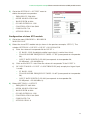
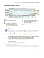
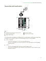
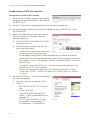
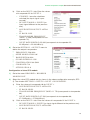
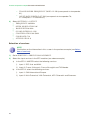
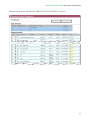
1
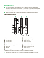
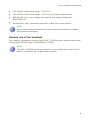
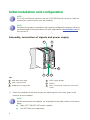
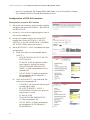
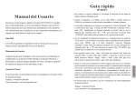
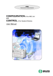
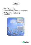
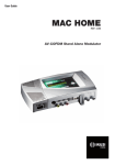
Quick installation and configuration guide
STC
200
REF. 4466
Contents
4Introduction
4
General description
5
General use of the headend
6
Initial installation and configuration
6
Assembly, connection of signals and power supply
7
IKUNET bus configuration
11
Practical configuration examples
11
Direct connection with universal LNB parabolic antenna
17
Connection with multiswitch
Introduction
JJ
The quick installation and configuration guide is a practical reference. To ensure the
correct use and installation of the headend, it is necessary to read the user manual and
troubleshooting procedure corresponding to the complete solution and to each of the
individual modules.
JJ
IKUSI reserves the right to modify the contents of this guide without prior warning.
General description
1
2
3
4
5
6
7
STC-200
9
15
10
16
11
12
13
8
14
KEY
7
RJ-45 ports for IKUNET bus
A
STC-200 module
8
Coupling loop DVB-T output
B
CFP-700 module
9
Output +12 V (5 A)
C
CFP-507 module
10 Output +24 V (60 mA)
1
Input 1 DVB-S/S2 channel
11 Output +18 V/22 kHz (300 mA)
2
Input 2 DVB-S/S2 channel or loop output
12 Output +13 V/22 kHz (300 mA)
3
LNB remote power supply
13 Output +18 V/0 kHz (300 mA)
4
Slot for CAM
14 Output +13 V/0 kHz (300 mA)
5
DB-9 port
15 Output +12 V (7 A)
6
DC power supply
16 Output +24 V (60 mA)
The headend described in this manual is made up of the following modules:
JJ
4
STC-200 (Ref. 4466): DVB-S/S2 to DVB-T transmodulator (QPSK/8PSK to COFDM).
Introduction/General use of the headend
JJ
CFP-507 (Ref. 4439): power supply +12 V/+24 V.
JJ
CFP-700 (Ref. 4401): power supply +12 V/+24 V for selection of polarisation.
JJ
BAS-900 (Ref. 4411): base-support with capacity for 9 modules (dimensions:
563x257x24 mm).
JJ
MS-0504 (Ref. 1023): stand-alone multiswitch (4 SAT inputs and 4 outputs).
EN
NOTE
Please read the detailed information in the manuals for the modules included in
their respective packaging.
General use of the headend
This headend is designed for the emission of DVB-T (COFDM) signals from the input of free
or encrypted DVB-S/S2 signals (QPSK/8PSK to COFDM).
NOTE
The DVB-T (COFDM) output signal requires a trunk amplifier for the correct distribution in installations for a large number of sockets.
5
Initial installation and configuration
NOTE
A PC with an Ethernet network card and a CAT-5E Ethernet crossover cable are
required for communication with the headend.
NOTE
To display the graphics provided in the headend configuration program correctly,
we recommend installing the Mozilla Firefox web browser (www.mozilla.com) in
the control PC.
Assembly, connection of signals and power supply
3
1
2
4
5
6
KEY
1
DVB-S/S2 signal input
4
Power supply bridges
2
DVB-T signal output
5
IKUNET
3
Bridging line in loop mode
6
CAM + SmartCard + protection with safety
screws
1) Attach the modules to the base one by one following the instructions given in the
manuals for each module.
NOTE
IKUSI recommends the modules are assembled in the order shown in the above
figure;
6
JJ
Right: CFP-700/CFP-507 power supplies.
JJ
Left: STC-200 transmodulators.
Initial installation and configuration/IKUNET bus configuration
JJ
Last STC-200 on the right: Master STC-200 with the DVB-T output signal.
EN
2) Connect the input and output signal connections in accordance with the instructions
for the module manuals and the diagram shown in the previous figure.
3) Distribute the headend power supply as symmetrically as possible (see example in
above figure).
IKUNET bus configuration
The IKUNET bus is an Ethernet communication bus between the headend modules. The
IKUNET bus is installed using Ethernet pigtails supplied with the modules. If n is the number of station modules, n-1 Ethernet pigtails are required.
Definition of the master module
NOTE
JJ
Remember the PC configuration prior to the connection with the IKUNET
bus.
JJ
The definition of the master module must be made with an STC-200 module.
NOTE
In mixed STC and MTC configurations, an STC module may never be an MTC
module master. In these cases, the master module must be an MTC module and
the STC modules are reserved for configuration as slave modules.
1) Start the configuration of the IKUNET bus for
the headend with the modules disconnected
from each other.
2) Connect the selected module ( A ) to the PC
( B ) via its Ethernet connection and using an
RJ-45 cable ( C ).
STC-200
STC-200
3) In the PC (Windows XP) go to START > CONTROL PANEL > NETWORK CONNECTIONS
> LOCAL AREA CONNECTION > PROPERTIES > INTERNET PROTOCOL (TCP/IP) >
PROPERTIES.
4) Select the USE THE FOLLOWING IP ADDRESS checkbox. Enter the following IP
configuration parameters:
FF
IP ADDRESS: 10.254.254.2
FF
SUBNET MASK: 255.255.255.0
FF
DEFAULT GATEWAY: 10.254.254.1
5) Click on the ACCEPT button.
7
Initial installation and configuration/IKUNET bus configuration
6) Enter the IP address http://10.254.254.254 in the web browser. This takes you to the
home page of the connected module.
7) In the home page of the selected module,
“Admin” appears by default in the USER field.
Enter the word “admin” in the PASSWORD field
and click on ACCEPT.
8) The main management window for the STC-200
module as slave module is displayed.
NOTE
The module with which you have connected the PC disconnects automatically
after 15 minutes without interaction.
9) In the main menu, click on MASTER MODULE
> CONFIGURATION. The window GENERAL HEADEND PARAMETERS CONFIGURATION is displayed, with the INSTALATION DATA tab.
10) Enter the name of the module in the MODULE
NAME field.
NOTE
IKUSI recommends you give a description
to the module according to its position
in the headend in order to identify the
modules logically and physically. For example, for a configuration identical to that
proposed in the assembly section, include
the following identifications (on the base,
from right to left: STC-1 MASTER and
STC-2).
11) To activate the module as master of the headend, click on the THIS STC-200 IS THE MASTER MODULE checkbox. The module
will be configured as master once the window has been saved.
CAUTION
If the background of the field is red, this means that the data has been modified
but has not yet been saved. Before changing the window or tab, the modified
data must be saved (click on SAVE). Otherwise the modified data will be lost and
the headend will remain in the same state as before.
NOTE
If the IKUNET bus is connected to another Ethernet bus, we recommend you limit
the IP range to the number of slave modules in the IKUNET bus, so that these
can be identified more easily.
12) Click on EXIT in the main screen (top right corner).
8
Initial installation and configuration/IKUNET bus configuration
Name of slave modules
EN
Continue with the IKUNET bus without connecting.
Follow the steps below for each of the remaining modules of the headend (slave modules).
1) Connect the selected module ( A ) to the PC
( B ) via its Ethernet connection and using an
RJ-45 cable ( C ).
2) Enter the IP address http://10.254.254.254 in
the web browser. This takes you to the home
page of the connected module.
STC-200
STC-200
3) In the home page of the selected module,
“Admin” appears by default in the USER field.
Enter the word “admin” in the PASSWORD field
and click on ACCEPT.
4) Enter the name of the module in the MODULE
NAME (STC-2) field.
CAUTION
The checkbox THIS STC-200 IS THE MASTER MODULE must be left unmarked for the slave modules.
5) Click on SAVE.
6) Click on EXIT in the main screen (top right corner).
General configuration of the headend
When the master module for the headend has been defined, access to the headend is via
the master module. To access the master module it is necessary to configure the IP access
of the PC and enter another IP address in the web browser.
1) Connect the IKUNET bus for the headend with the Ethernet pigtails supplied with each
module (see example in the figure in the General description section).
2) In the PC, modify the IP address, following the same steps as in Definition of the
master module, but including the following parameters:
FF
IP ADDRESS: it should follow the root of the IP address for the master module of
the headend, but be out of its range. The address recommended by IKUSI for the
default configuration of the master module is 192.168.1.2.
FF
SUBNET MASK: 255.255.255.0
FF
DEFAULT GATEWAY: 192.168.1.1
3) Click on the ACCEPT button.
9
Initial installation and configuration/IKUNET bus configuration
4) In the web browser, enter the IP address of
the master module. The default address is
http://192.168.1.5. This takes you to the home
page of the headend master module.
5) In the home page of the selected module, enter
the word “Admin” in the PASSWORD field.
6) Click on ACCEPT. The main screen of the master module user interface is accessed through
the GENERAL HEADEND PARAMETERS
CONFIGURATION > INTALLATION DATA
window.
Module registry
To prevent the headend from losing its general
configuration, the modules must be registered.
1) Go to the menu HEADEND > HEADEND
MODULE LIST. The list of modules connected to the IKUNET bus should appear on the
screen. Each row corresponds to a module. The
recognition status in IKUNET and the module
registry in the configuration of the headend can
be distinguished by the colour of each row:
FF
Blue: the module has been recognised
in the IKUNET bus but has not yet been
registered.
FF
Red: the module is not recognised in the
IKUNET bus and has been registered previously.
FF
Light green: the module is recognised in the
IKUNET bus and has been registered.
2) To register the identified modules, select the checkbox in the REGISTER column for
all the modules which form part of the headend and click on REGISTER.
10
Practical configuration examples
EN
NOTE
To start the headend configuration, first define the master module and the identification of the slave modules for the header, as described in the Initial installation and configuration section.
Direct connection with universal LNB parabolic antenna
STC-200
STC-200
KEY
1
2
DVB-S/S2 signal input from universal LNB
antenna
A
STC-200 modules
B
CFP-700 power supply
DVB-T signal output
In this example, the headend is configured with a digital satellite input signal from a
universal LNB amplifier to emit the following services via:
JJ
JJ
STC-1 MASTER:
FF
Astra VL transponder 20: Al Jazeera English and BFM TV services.
FF
Astra VL transponder 22: France 24 français, France 24 english and TV5 Monde
services.
STC-2:
FF
Astra VL transponder 26: CNBC Europe, BBC World News and Bloomberg Europe
services.
11
Practical configuration examples/Direct connection with universal LNB parabolic antenna
FF
Astra VL transponder 58: Cadena SER, M80 Radio, Los 40 Principales, Cadena
Dial, Radiolé, Máxima FM and Sinfo Radio services.
Configuration of STC-200 modules
Configuration of master STC module
1) Go to the user interface for the master module
and go to the menu HEADEND > HEADEND
MODULE LIST.
2) In the list, click on the magnifying glass icon in
the master module row.
3) In the next window, select the master STC
module tab. Go to SETTINGS > MULTISWITCH. In the MULTISWITCH, NUMBER
OF INPUTS field, select the value “0“.
4) Go to SETTINGS > INPUT to define the input
transponders.
a)
Enter the values for transponder 66 for
INPUT 1.
ÌÌ
ÌÌ
ÌÌ
ÌÌ
MULTISWITCH OUTPUT: MULTISWITCH OFF.
FI BAND: LOW (the digital satellite
input signal is vertical low Astra).
TRANSPONDER FREQUENCY
(MHZ): 11 509 (corresponds to transponder 20).
INPUT RATE: 22 000 (corresponds
to transponder 66; 22 MSymb/s =
22 000 KBits/s).
b) Click on the INPUT 2 tab and enter the
values for transponder 22:
ÌÌ
ÌÌ
ÌÌ
ÌÌ
ÌÌ
12
STANDBY : do not mark the box (processed signal input).
RF INPUT MODE: 1 INPUT +
LOOPTHROUGH (only one physical
signal input is used).
FI BAND: LOW
TRANSPONDER FREQUENCY :
11 538 (transponder 22).
INPUT RATE: 22 000 (corresponds
to transponder 22; 22 MSymb/s =
22 000 KBits/s).
Practical configuration examples/Direct connection with universal LNB parabolic antenna
5) Go to the SETTINGS > OUTPUT menu to
define the output transponders.
FF
FREQUENCY: 506 MHz
FF
OFDM MODULATION: 8K
FF
BANDWIDTH: 8 MHz
FF
GUARD INTERVAL: 1/32
FF
CONSTELLATION: 64 QAM
FF
CODE RATE: 7/8
FF
ATTENUATION: 0
EN
Configuration of slave STC module
1) Go to the menu HEADEND > HEADEND
MODULE LIST.
2) Select the slave STC module tab (as shown in the previous example, “STC-2”). The
window SETTINGS > INPUTS > INPUT 1 IS DISPLAYED.
a)
Enter the values of transponder 26 for INPUT 1:
ÌÌ
ÌÌ
ÌÌ
FI BAND: LOW (the digital satellite input signal is vertical low Astra).
TRANSPONDER FREQUENCY (MHZ): 11 597 (corresponds to transponder
26).
INPUT RATE (KBITS/S): 22 000 (corresponds to transponder 26;
22 MSymb/s = 22 000 KBits/s).
b) Click on the INPUT 2 tab. Enter the values of transponder 76 for INPUT 2:
c)
RF INPUT MODE: 1 INPUT + LOOPTHROUGH (only one physical signal input
is used):
ÌÌ
ÌÌ
ÌÌ
FI BAND: LOW.
TRANSPONDER FREQUENCY (MHZ): 10 847 (corresponds to transponder
58).
INPUT RATE (KBITS/S): 22 000 (corresponds to transponder 58;
22 MSymb/s = 22 000 kBits/s).
3) Select SETTINGS > OUTPUT
FF
FREQUENCY: 482 MHz
FF
OFDM MODULATION: 8K
FF
BANDWIDTH: 8 MHz
FF
GUARD INTERVAL: 1/32
FF
CONSTELLATION: 64 QAM
FF
CODE RATE: 7/8
FF
ATTENUATION: 0
13
Practical configuration examples/Direct connection with universal LNB parabolic antenna
Selection of input services
1) To define the services to be emitted through the
output of the DVB-T output signal, go to
SERVICES > SERVICE MANAGEMENT. In
the upper side of the HEADEND SERVICE
MANAGEMENT window there is a table
showing the services available in the input,
differentiated by modules.
KEY
1
Selection of STC module.
2
Selection of service to the output signal (if the
checkbox is not displayed, the service has
already been selected at the output).
3
Service type.
Lock closed = encrypted.
Lock open = free.
4
Service: name of service (contextual menu
when passed with the cursor: information on
Service ID).
5
Input: module input number (contextual menu
when passed with the cursor: information on
Original Network ID and Transport Stream ID).
6
original LCN: Logic Control Number emitted
by the operator.
2) Click on the icon on the left of the row of each module (position 1 in the above figure)
to go to the list of input services.
a)
To select a particular service, select the checkbox in the ADD column ( 2 ).
b) When all the services of a module have been enabled for the output signal, click
on the SAVE SERVICES button.
14
Practical configuration examples/Direct connection with universal LNB parabolic antenna
Management of output services
EN
KEY
1
Deletion of the output service.
2
Lock open: service processing not encrypted.
3
Lock closed: service encrypted.
“Ok” icon = unencryption correct.
“Not ok” icon = unencryption failed.
4
LCN: Logic Control Number emitted by the
DVB-T output signal of the headend.
Yellow cell = LCN free.
5
Monitoring of available output signal bandwidth.
NOTE
If the bandwidth is saturated, delete the output services not required selecting
the checkboxes in the DELETE column ( 1 ) and clicking on SAVE SERVICES.
JJ
LCN management ( 4 ):
FF
The DVB-T input services have an LCN (Logic Control Number) which is transmitted in the output services (see LCN column).
FF
The DVB-S/S2 input services do not usually have an LCN. The headend automatically allocates an LCN for the DVB-T output signal of these services.
FF
To modify a free LCN (see LCN column, cells with yellow background):
i)
Place the cursor in the LCN cell to be modified.
ii) Modify the LCN.
iii) Click on the SAVE LCN VALUES button.
JJ
Output services saturation level:
The saturation level of the output multiplexes can be controlled with the instruction on
empty packets (stuffing) and the information about the data transfer speed ( 5 ).
15
Practical configuration examples/Direct connection with universal LNB parabolic antenna
FF
FF
16
The information on empty packets reflects the available bandwidth in the output
multiplex and is indicated in real time in the lower table OUTPUT BITRATE of the
HEADEND SERVICES MANAGEMENT window with the following columns:
ÌÌ
MAX BITRATE: data transfer speed of the output multiplex.
ÌÌ
MIN. NULL: minimum percentage of empty packets performed.
ÌÌ
ACT. NULL: percentage of actual empty packets.
ÌÌ
MAX. NULL: maximum percentage of empty packets performed.
The BITRATE column in the above tables INPUT SERVICES and OUTPUT
SERVICES provides information on the individual data transfer speed for each
service.
Practical configuration examples/Connection with multiswitch
Connection with multiswitch
STC-200
EN
STC-200
KEY
1
DVB-S/S2 signal input from LNB “quattro”
antenna and multiswitch
2
DVB-T signal output
A
STC-201 modules
B
CFP-700 power supply
In this example, the headend is configured with a multiple digital satellite input signal from
an antenna with “quattro” LNB to emit the following services via the modules:
JJ
JJ
STC-1 MASTER
FF
Astra HH transponder 77: ZDF, 3sat and KIKA services.
FF
Astra VL transponder 22: France 24 français, France 24 english and TV5 Monde
Europe services.
STC-2
FF
Astra VH transponder 68: CNN International Europe service.
FF
Astra HH transponder 91: Nick Österreich, VIVA Österreich, MTV Österreich and
Euronews services.
17
Practical configuration examples/Connection with multiswitch
Configuration of STC-200 modules
Configuration of master STC module
1) Go to the user interface for the master module
and go to the menu HEADEND > HEADEND
MODULE LIST.
2) In the list, click on the magnifying glass icon in the master module row.
3) In the next window, select the master STC module tab. Go to SETTINGS > LNB/
MULTISWITCH.
4) Identify the LNB local oscillator type (relevant
for the calculation of FI based on the transponder frequency):
a)
MULTISWITCH, NUMBER OF INPUTS:
select the value “4”.
b) Enter the names and characteristics for
each multiswitch input:
i)
ÌÌ
ÌÌ
SATELLITE: Name of the input signal
to the multiswitch for identification
in subsequent configurations. IKUSI recommends you identify the type of
satellite, polarity and the bandwidth of the signal. In this example, the name of
the satellite is “Astra”, V/H polarities (VERTICAL/HORIZONTAL), H/L band
(HIGH/LOW).
POLARITY: Select VERTICAL (13 V) for the second and third inputs and
HORIZONTAL (18 V) for the other.
BAND: For each polarity select HIGH (22 KHZ) once [INPUT 1 AND 4:
ASTRA HH; INPUT 3: ASTRA VH] and LOW (0 KHZ) [INPUT 2: ASTRA
VL] once.
5) Go to the SETTINGS > INPUT menu to define
the input transponders.
a)
Enter the values of transponder 77 for
INPUT 1:
ÌÌ
ÌÌ
ÌÌ
ÌÌ
18
MULTISWITCH OUTPUT: ASTRA
HH.
FI BAND: HIGH.
TRANSPONDER FREQUENCY
(MHZ): 11 954 (corresponds to transponder 77).
INPUT RATE (KBITS/S): 27 500
(corresponds to transponder 77;
27.5 MSymb/s = 27 500 kBits/s).
Practical configuration examples/Connection with multiswitch
b) Click on the INPUT 2 tab. Enter the values
of transponder 22 for INPUT 2:
ÌÌ
ÌÌ
ÌÌ
ÌÌ
ÌÌ
ÌÌ
EN
STANDBY : leave the checkbox
unticked (the input signal is processed).
RF INPUT MODE: 2 INPUTS (an
input signal different to the previous
one).
MULTISWITCH OUTPUT: ASTRA
VL.
FI BAND: LOW.
TRANSPONDER FREQUENCY
(MHZ): 11 538 (corresponds to transponder 70).
INPUT RATE (KBITS/S): 22 000 (corresponds to transponder 22;
22 MSymb/s = 22 000 kBits/s).
6) Go to the SETTINGS > OUTPUT menu to
define the output transponders.
FF
FREQUENCY: 506 MHz
FF
OFDM MODULATION: 8K
FF
BANDWIDTH 8 MHz
FF
GUARD INTERVAL: 1/32
FF
CONSTELLATION: 64 QAM
FF
CODE RATE: 7/8
FF
ATTENUATION: 0
Configuration of slave STC module
1) Go to the menu HEADEND > HEADEND
MODULE LIST.
2) Select the slave STC module tab (as shown in the above configuration example, STC2). The window SETTINGS > INPUTS > INPUT 1 IS DISPLAYED.
a)
Enter the values of transponder 68 for INPUT 1:
ÌÌ
MULTISWITCH OUTPUT: ASTRA VH.
ÌÌ
FI BAND: HIGH.
ÌÌ
ÌÌ
TRANSPONDER FREQUENCY (MHZ): 11 778 (corresponds to transponder
68).
INPUT RATE (KBITS/S): 27 500 (corresponds to transponder 68;
27.5 MSymb/s = 27 500 kBits/s).
b) Click on the INPUT 2 tab. Enter the values of transponder 91 for INPUT 2:
ÌÌ
RF INPUT MODE: 2 INPUTS (an input signal different to the previous one).
ÌÌ
MULTISWITCH OUTPUT: ASTRA HH.
ÌÌ
FI BAND: HIGH.
19
Practical configuration examples/Connection with multiswitch
ÌÌ
ÌÌ
TRANSPONDER FREQUENCY (MHZ): 12 226 (corresponds to transponder
91).
INPUT RATE (KBITS/S): 27 500 (corresponds to transponder 76;
27.5 MSymb/s = 27 500 kBits/s).
3) Select SETTINGS > OUTPUT
FF
FREQUENCY: 482MHz
FF
OFDM MODULATION: 8K
FF
BANDWIDTH: 8 MHz
FF
GUARD INTERVAL: 1/32
FF
CONSTELLATION: 64 QAM
FF
CODE RATE: 7/8
FF
ATTENUATION: 0
Selection of services
NOTE
Clarification on the information in this screen in the previous example (see Selection of services).
1) Go to SERVICES > SERVICE MANAGEMENT.
2) Select the input services in the STC modules (see above example).
a)
In the STC-1 MASTER select the following services:
i)
Input 1: ZDF, 3sat and KIKA.
ii) Input 2: France 24 français, France 24 english and TV5 Monde.
b) In the STC-2 select the following services:
i)
Input 1: CNN International Europe.
ii) Input 2: Nick Österreich, VIVA Österreich, MTV Österreich and Euronews.
20
Practical configuration examples/Connection with multiswitch
The final result of the HEADEND SERVICE MANAGEMENT screen is:
EN
21
Ángel Iglesias, S.A.
Paseo Miramón, 170
20009 San Sebastián, Spain
Tel. +34 943 44 88 00
Fax +34 943 44 88 20
[email protected]
www.ikusi.com