1
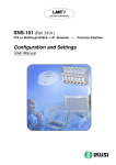
Television on IP Networks
SNS-100 (Ref. 5100)
DVB-S ➞ IP Streamer
Configuration and Settings
User Manual
EN
Configuration and Setting of the SNS-100 Streamer Module
User Manual
March 2007
Revision A
IKUSI - Ángel Iglesias, S.A.
Paseo Miramón, 170
20009 San Sebastián
SPAIN
Tel.: +34 943 44 88 00
Fax: +34 943 44 88 11
www.ikusi.com
CONTENTS
Introduction ............................................................................................................................. 4
This Manual ................................................................................................................. 4
Product Description ...................................................................................................... 4
Chapter One - Configuration of the SNS-100 Streamer ......................................................... 5
Configuration ........................................................................................................... 6-10
Save/Restore Configuration ....................................................................................... 11
General Report .......................................................................................................... 12
Chapter Two - SNS-100 Streamer Settings .......................................................................... 13
Input Settings ........................................................................................................ 14-16
Output Settings ..................................................................................................... 17-19
SAP/SDP Channel Settings ....................................................................................... 20
Chapter Three - SNS-100 Streamer Status Information ....................................................... 21
Status Information ...................................................................................................... 22
Chapter Four - SNS-100 Streamer Reports .......................................................................... 23
Input Services ............................................................................................................ 24
Output Streams .......................................................................................................... 25
System Logs .............................................................................................................. 26
3
Introduction
This Manual
This manual describes the configuration and settings programme for the SNS-100 Streamer Module.
It is the second part of the user documentation for said module, the first part of which is the Installation
and Access manual supplied in paper format.
Product Description
SNS-100 streamers are DVB-S to IP gateways designed to broadcast in multicast the services (TV or Radio
programmes) from a digital satellite reception on an IP network. The IP streams can be viewed using an IPTV
set-top box or a software video player.
SNS-100 modules have an IKUSI ClassA mechanical format. As such, they are fixed to BAS-700 / BAS-900
baseplates or to an SMR-600 rack frame, and are +12 VDC powered from a CFP module.
Characteristics
Input: 1 DVB-S transport stream (MPTS). Output: up to 8 simultaneous, IP-encapsulated services (TV or Radio programmes),
with individual multicast addresses.
Information filtering of MPEG-2 tables.
UDP & RTP transmission protocols.
Web interface for configuration and setting.
SAP & SDP protocols which facilitate automatic service selection on the user's STB and the supply of information to external
servers.
ADVANCED
PID filtering
PSI/SI parsing
Transparent ECM & EMM messaging
PAT and PMT table regeneration
Routing or blocking for CAT, NIT, SDT, EIT, TDT tables
Configurable QoS marking
Configurable Time To Live
When a connection is established between the SNS-100 streamer and the control PC, the programme
access screen will appear:
Programme Access Screen
Once the desired programme language has been chosen [Spanish (es), English (en), French (fr) ], enter
the password and click on OK.
Note: The default password — admin — can (and must) be changed as explained on page 9.
4
Chapter One - Configuration of the SNS-100 Streamer
In this Chapter
●
Configuration
●
Save/Restore
●
General Report
5
Configuration
General Configuration
Initial program screen
The first screen that appears
when the programme is
accessed contains the "Output"
window, which gives information
on the IP streams that have
been created on the module and
which may or may not be
incorporated into the output data
stream.
On the left of this screen are the
menus that access all of the
programme's functionalities.
Figure 1.1 - Initial programme screen
Click on the General menu on the left of the screen to display a dropdown list
containing the 3 options: Configuration, Save/Restore and General Report.
Click on Configuration. The Configuration window will appear :
Figure 1.2 - Identification card of the Configuration window.
Identification
The identification card (Figure 1.2) provides basic data on the SNS-100 streamer. The
different card fields are completed as follows:
6
Configuration
"Model": SNS-100. This data cannot be changed.
"Serial Number": Informational data which cannot be changed.
"Firmware Version": As above.
"Identifier": Any name that the installer or operator wishes to assign to the streamer
module can be entered here.
"Location": Enter the postcode of the installation site if required.
"Installer": The installer's identification details can be entered here.
"Contact": Then enter their contact details (telephone number, email).
"Installation date": The date on which the streamer module was installed can be
entered here.
Click on the Save button at the bottom of the window to store the information on the streamer module, this
information is then shown each time the module is accessed.
7
Configuration
Network
Click on the Network tab to configure the streamer's ethernet connection parameters.
The following card is displayed:
Figure 1.3 - Network card of the Configuration window.
"Use DHCP to get IP address": If this box is checked, the SNS-100 module will use
the DHCP protocol for assigning dynamic IP addresses. Consequently, no data
needs to be entered in the next five fields on the tab.
If the administrator of the network on which the SNS headend is installed assigns
static IP addresses, the box will not be checked and the following fields will need to
be filled in.
WARNING: If this option is activated, the IP address assigned to the streamer can
only be known by consulting the DHCP server management system.
"IP Address": Enter the IP address that you wish to assign to the streamer. This
address must fall within the range of local network addresses.
"Network mask": Enter the local network mask.
"Default gateway": Enter the IP address of this gateway. This information is only
required if you want the streamer to access Internet.
"Primary DNS server": Enter the primary server's IP address. Equally, this
information is only required if you want the streamer to access Internet.
"Secondary DNS server": Enter the same information for the secondary server.
"MAC Address": The physical address of the streamer's ethernet network card is
displayed automatically.
Once you have filled in all of the required information, click on Modify Network Configuration. If, at the last moment,
you decide to keep the current settings, click on Restore.
8
Configuration
Password
If you want to change the current access password, click on the Password tab. The
following card is displayed:
Figure 1.4 - Password card of the Configuration window.
"Current password": Enter the current password.
"New password": Enter the new password which will be required to access the
program the next time.
"Confirm new password": Re-enter the new password.
Once you have entered the required information, click on Modify so that the streamer adopts the new access
password. If, at the last moment, you decide to keep the previous password, click on Cancel.
!
Note
If you do not know the old password, i.e. the password used to access the current configuration
session, you must perform a Password Reset as explained in the Installation and Access manual.
Following this reset, the program password will be the default password: admin.
IMPORTANT: When you perform a password reset, the IP address assigned to the streamer on the
Network card (previous page) automatically changes to the default setting: http:// 92.168.1.4.
Shutdown
If you need to reboot the streamer for any reason, click on the Shutdown tab. The
following card is displayed:
Figure 1.5 - Shutdown card of the Configuration window.
Click on Reboot. A reset is then performed after which the Output Streams screen
will appear, this is the presentation screen of the programme.
9
Configuration
Update Firmware
If you wish to update the streamer's firmware, click on the Update Firmware tab. The
card displayed (Figure 1.6) shows the firmware version that the streamer has at the
present time.
(The firmware is software stored in the module which is responsible for its basic operation).
Figure 1.6 - Update Firmware card of the Configuration window.
WARNING: The firmware update file will have been previously stored on the PC hard drive. (You can
download it from http://www.ikusi.com).
Click on Browse... and select the firmware update file from the hard drive. When the file
name is in the box, click on Start. The new firmware will be installed on the streamer
and then its name will appear in the card replacing the one of the file before.
10
Save/Restore
Save/Restore System Settings
All of the data established on the streamer module through the various Configuration
window tabs can be saved onto a backup file. Inversely, the configuration data saved on
an appropriate file can be restored on streamer module.
Click on the General menu on the left of the general programme screen and click again
on the Save/Restore option. The Save/Restore window will appear:
Figure 1.7 - Save/Restore window
Save/Restore Configuration
"Save configuration": Select the option in the window and click on Start. A window
is displayed which allows you to select the destination folder for the data file for the
current streamer configuration.
"Restore Configuration": Select this option in the Save/Restore window
(Figure 1.7) and click on Start. The Restore Configuration window is displayed (Fig.
1.8) Click on Browse... and select the file containing the configuration data that you
wish to restore on the streamer module. Once you have selected the file, click on
the Upload File button at the bottom of the screen. The upload confirmation window
will be displayed.
Figure 1.8 - Restore Configuration Window
11
General Report
General Report
Click on the General menu on the left of the general programme screen and click again
on the General Report option. The General Report window is displayed:
Figure 1.9 - General Report window
This window provides complete information on the SNS-100 module, not only regarding
the configuration described in the previous pages, but also in relation to the current
settings parameter values and operational status.
The information contained in this window can be printed by clicking on the Print page
button at the bottom of the screen.
12
Chapter Two - SNS-100 Streamer Settings
In this Chapter
●
Input Settings
●
Output Settings
●
SAP/SDP Channel Settings
13
Input
Input Settings
The SNS-100 module settings are grouped into three sections or categories: Input,
Output and SAP/SDP Channel. Click on the Settings menu on the left side of the general programme screen. A drop down list with the three option for this menu is displayed:
Input, Output and SAP/SDP Channel.
Click on Input. The Input window will appear:
Figure 2.1 - Input window
This window is used to enter the settings values for two parameters: Intermediate
Frequency (MHz) and Input Rate (MS/s). The intermediate frequency is the transposed
frequency of the desired transponder's frequency.
The window has 3 main boxes —the first three at the top— and 5 auxiliary boxes.
These auxiliary boxes are only completed if Transponder is selected in the first box
("Setting Mode").
"Setting Mode": Select IF if the intermediate frequency value is calculated by the
installer, or Transponder if you wish the programme itself to perform the calculation.
IF CALCULATION
The SNS-100 streamer's input frequency band is 950-2150 MHz, known as "satellite
intermediate frequency" or simply "IF". The value to enter for a particular transponder can
be obtained by subtracting the transponder's frequency from the LNB local oscillator
frequency.
The operational frequencies are the following:
- Satellite transponder frequency band: 10700-12750 MHz
- Local Oscillator frequency on Standard LNB's. Two possible values:
9750 MHz for 10700-11700 MHz input frequencies (low band)
10600 MHz for 11700-12750 MHz input frequencies (high band)
- Example of the calculation for FI relating to the WDR program transponder on the
Astra satellite:
Transponder frequency: 11836 MHz
IF (intermediate frequency): 11836 - 10600 = 1236 MHz
14
Input
"IF" setting mode is selected:
Figure 2.2 - Input Window — IF Mode
Only the second and third boxes of the window need now be completed :
"Intermediate Frequency (MHz)": Enter the value calculated for the transposed
intermediate frequency of the transponder's frequency in the box. The latter can be
found in specialist magazines.
"Input Rate (MS/s)": This parameter, best known and Symbol Rate, is also
provided in specialist magazines. Enter the value in MS/s (megasymbols per
second) or MegaBaud.
Once the data is entered, click on Save so that the streamer adjusts to the intermediate frequency and the input
rate shown in the respective boxes.
"Input signal": This indicates whether the streamer module has synchronised (✓)
or not (✖) with the input signal. If it has not synchronised, check the settings values
entered in the second and third boxes.
"Transponder" setting mode is selected:
Figure 2.3 - Input window — Transponder Mode - LNB Standard
In this case, the programme will itself complete the second box "Intermediate
Frequency (MHz)", based on the data entered in the last 5 boxes (the auxiliary
boxes), as indicated next:
15
Input
"LNB Type": The drop down list has 2 options: Standard LNB and Special LNB.
If the LNB installed on the parabolic antenna is standard, select the Standard LNB
option. The boxes "Low LO Frequency" and "High LO Frequency" will be
automatically completed with values 9750 and 10600 respectively (see Figure 2.3
on the previous page).
If the LNB installed is Special, select the Special LNB option on the drop down list
(see Figure 2.4 below).
"Transponder Frequency (MHz)": Enter the required transponder frequency.
"Low LO Frequency (MHz)": The value is automatically shown if Standard LNB was
selected. You must manually enter this value if you have selected Special LNB.
"High LO Frequency (MHz)": As above.
"IF Band": Select Low or High from the drop down list depending on the
transponder frequency: low for 10700-11700 MHz and high for 11700-12750 MHz.
When the selection is complete the corresponding value will automatically be
calculated by the programme and displayed in the Intermediate Frequency box.
"Input Rate (MS/s)" : This parameter, best known as Symbol Rate, is also provided
in specialist magazines.
Once the different data values have been entered, click on Save so that the streamer adjusts to the intermediate
frequency and the input rate shown in the 2nd and 3rd boxes of the window.
"Input signal": This indicates if the streamer module has synchronised (✓) or not
(✖) with the input signal. If it has not synchronised, check the settings values that
appear in the second and third boxes.
Figure 2.4 - Input window — Transponder Mode - Special LNB
16
Output
Output Section Settings
Click on the Settings menu on the left of the general programme screen and click
again on the Output option. The Output windown will appear:
Figure 2.5 - Output window
This window is used to select and configure the required services (TV or Radio
programs) from the DVB-S input transport stream as IP streams. The window displays
three boxes at the top, and in the centre it displays a table showing the IP streams
already configured and which may or may not be transmitted by the streamer module
(see NOTE below). For each stream it shows the multicast address and the different
parameters such as the PID of the main stream or the total bandwidth in Mbps.
"Protocol": The drop down menu offers two options : UDP and UDP/RTP. UDP is a
transport protocol which is not connection oriented and is particularly useful for
streaming. UDP/RTP adds extra data fields so that the data flow is served at the
correct speed for its projection in real time.
"Time To Live": Is a parameter used to restrict the stream multicasting range. A
number between 1 and 255 is entered in this box. Each time that an IP stream
passes through a router, the TTL is reduced by one unit. The stream will be
rejected by any router when the TTL value is reduced to zero.
"QoS": Quality of Service. The drop down list offers five differentiated service
options or Diffserv. These options relate to the priority that you wish to assign to the
streaming packets on their routes through switches or routers that are QoS
management capable:
1 Maximum priority
2 High priority video
3 Low priority video
4 Video and voice
5 Best effort (best effort made to correctly deliver the video data and the associated audio data)
NOTE: Configured IP Streams are those that have been created in the manner
described on the following page. These streams may or may not be
incorporated into the data stream depending on whether their corresponding
ON/OFF boxes in the first column are checked or not. The number of checked
boxes cannot be more than 8.
17
Output
The Output window allows you to perform three actions:
- Add Stream: This adds a new IP stream to the display table.
- Edit Stream: Allows you to change the parameters of the IP stream on the display table.
- Delete Stream: Deletes an IP stream from the display table.
Add Stream
Click on the Add Stream button at the bottom of the Output window (see Figure 2.5 on
the previous page). The Add Stream window is displayed:
Figure 2.6 - Add Stream window
The window shows all of the input DVB-S transport stream services, including different
details (name, type, identifier, main PID, provider). Highlighted in orange are those
services which are already configured as IP streams (seen in the display table in the
Output window) and highlighted in green are those which are not yet configured.
To add a stream to the display table, select the button for the corresponding service in
the first column. The line will be highlighted in pink and at the bottom of the screen a
group of boxes will appear which relate to the elemental streams associated with the
main stream of the service.
The boxes at the top and middle of the screen will now be completed, and the elemental streams at the bottom will be configured:
18
Output
Boxes at the top of the screen:
"Multicast Stream Address": Enter the multicast address required for the stream to
be added. The available range is from 224.0.0.0 to 239.255.255.255.
"Port": The default value is 1234.
"SAP ID": Is the name given to the service on the subscriber's set-top box or
reproducer, if the device supports SAP/SDP protocol. The name that the service
has on the input transport stream is the default name.
Box in the middle of the screen:
"Send full PMT": Leave this box checked if you wish to send the complete PMT
table (Program Map Table) for the service. Otherwise, if you would like to refrain
from sending certain PIDs that are not relevant to the elemental streams associated
with the main stream (bottom boxes) remove the check from the box.
Bottom boxes:
Only in cases where the "Send full PMT" box is NOT checked can you make the
selections that you wish on each of the elemental streams associated with the main
stream: audio, subtitles, teletext, etc.
Once all data is entered and the appropriate selections have been made, click on Update to add the new IP stream
to the display table in the Output window.
Edit Stream:
You can change the parameters of an IP stream displayed in the table on the Output
window. Click on the icon
at the end of the line. The previously described Add
Stream screen is displayed, where you can change any editable field, from the multicast
address to the elemental stream selections in the boxes at the bottom.
Once all changes that you require are made, click on Update and the IP stream will be displayed with its new
configuration in the display table in the Output window.
Delete Stream:
If you wish, you can delete an IP stream from the display table on the Output window.
To do so, click on the icon
at the end of the line.
19
SAP/SDP Channel
SAP/SDP Channel Settings
Click on the Settings menu on the left of the general programme screen and click
again on the SAP/SDP Channel option. The SAP/SDP Channel window will appear:
Figure 2.7 - SAP/SDP Channel window
This menu option is used to configure the announcement and service description SAP/
SDP channel. SAP and SDP are two protocols for creating an EPG type program guide.
"SAP Activated": Check the box if you wish to transmit the program guide.
"SAP IP address": This data cannot be changed. It is the IP address assigned to
the streamer module on the Network tab in the Configuration window (page 8).
"Username": The name entered will be transmitted on the SAP/SDP channel.
"Group": As above.
"Time interval between SAP announcements": Introduce the time interval, in
seconds, at which the transmitted programmes guide will refresh.
Click on Save to save the SAP/SDP channel configuration data.
20
Chapter Three - SNS-100 Streamer Status Information
In this Chapter
●
Status Information
21
Status Information
Status Information
Click on the Status menu on the left of the general programme screen and click again
on the Status Information option. The Status Information window appears:
Figure 3.1 - Status Information window
This window gives you information on the existence of alarms for module operations
and on the importance reception and transmission parameters:
"Hardware Alarm" : Indicates whether there is an anomaly in the modules circuitry.
A ✓ mark indicates correct status or operations and a cross ✖ warns of an alarm
situation.
"Input": Indicates whether there is (✓) synchronisation or not (✖) with the input
signal. In cases where there is not synchronisation, check the settings made in the
Input Settings (pages 14 to 16).
"BER": Expresses in scientific notation the channel BER value for the input signal.
"C/N (dB)": The value in dB of the carrier/noise ratio of the input signal.
"Number of Streams": Number of IP streams currently transmitted by the SNS-100
module.
«Bandwidth»: Value in Mbps.
"Information Sent (MB)": Expresses in scientific notation, the amount of information
(in megabytes) which has been transmitted by the internal web server since the last
module reset.
"Information Received (MB)": The same for information received.
22
Chapter Four - SNS-100 Streamer Reports
In this Chapter
●
Input Services
●
Output Streams
●
System Logs
23
Input Services
Input Services
Click on the Reports menu on the left of the general programme screen and click again
on the Input Services option. The Input Services window appears:
Figure 4.1 - Input Services Window
The Input Services window shows the full information on each of the services contained
in the DVB-S input transport stream. In particular, it specifies the values of the following
parameters for each service:
- Name of the service
- Type
- SID (service identifier)
- PID of the main stream
- Service Provider
- PID, Type and Language of each one of the elemental streams associated
with the main stream
24
Output Streams
Output Streams
Click on the Reports menu on the left of the general programme screen and click again
on the Output Streams option. The Output Streams window will appear:
Figure 4.2 - Output Streams window
The Output Streams window shows all IP streams that have been created for this module. These streams may or may not be incorporated in the output data stream.
For each IP it shows the following details:
- ON/OFF (whether the stream is incorporated or not in the output data stream)
- IP Stream (multicast address)
- SID (service identifier)
- PID of the main stream
- Name of the service
- Type
- Total output bandwidth in Mbps
- SAP ID (name with which the service is announced on the subscriber's
receiver)
- Service Provider
- PID, Type and Language of each one of the elemental streams associated
with the main stream, indicating whether they are incorporated into the main IP
output stream or not.
25
System Logs
System Logs
Click on the Reports menu on the left of the general programme screen and click again
on the System Logs option. The System Logs window will appear:
Figure 4.3 - System Logs window
26
IKUSI - Ángel Iglesias, S.A.
Paseo Miramón, 170
20009 San Sebastián
SPAIN
Tel.: +34 943 44 88 00
Fax: +34 943 44 88 11
www.ikusi.com
ER-0149/1996