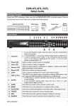
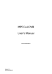
1
External Storage 200 Series
User’s Manual
Version 1.2
00P3DS200ZSEA2
User’s Manual
Table of Contents
1. Overview .......................................................................................................................3
2. Key Features .................................................................................................................3
3. Rear Connectors...........................................................................................................4
4. Setup the External Storage 200...................................................................................4
5. Front Panel Control/ LED Operation ...........................................................................6
5.1 System Information.................................................................................................8
5.1.1 Storage Information .....................................................................................9
RAID Type ...................................................................................................9
RAID Status .................................................................................................9
Total Capacity ..............................................................................................9
Total Disk .....................................................................................................9
5.1.2 Network Status.............................................................................................9
Hostname ....................................................................................................9
Workgroup ...................................................................................................9
Ethernet 1 (DVR Port)..................................................................................9
Ethernet 2 (LAN Port) ..................................................................................9
5.1.3 Version Info................................................................................................10
5.1.4 System log.................................................................................................10
5.2 System Setup .......................................................................................................10
5.2.1 Shutdown...................................................................................................10
5.2.2 System Time ..............................................................................................10
5.2.3 Network Setup ...........................................................................................10
5.2.3.1 Return Without Set .......................................................................10
5.2.3.2 Static ............................................................................................ 11
5.2.3.3 DHCP ........................................................................................... 11
5.2.3.4 ezNet............................................................................................ 11
6. Controlling from Web Page (Advanced) ...................................................................12
6.1 System Setup .......................................................................................................13
6.1.1
6.1.2
6.1.3
6.1.4
6.1.5
Basic Setup ...............................................................................................13
Time Setup ................................................................................................14
Network Setup ...........................................................................................14
Web Management .....................................................................................16
SNMP Setup ..............................................................................................17
6.1.6 Alarm Setup ...............................................................................................17
6.2 Storage Setup.......................................................................................................18
6.3 Share Setup .........................................................................................................19
6.3.1 DVR (NFS) Setup ......................................................................................19
6.3.2 FTP Setup..................................................................................................20
1
User’s Manual
6.3.3 Windows Networks ....................................................................................20
6.4 System Management............................................................................................21
6.4.1 System.......................................................................................................21
6.4.2 Software.....................................................................................................21
6.4.3 Configuration .............................................................................................22
Appendix A: To Change IP Address in Windows ..........................................................23
Appendix B: JBOD and RAID Types...............................................................................25
2
User’s Manual
1.
Overview
External Storage 200, with the RAID 0, RAID 1, RAID 5 and JBOD (Linear)
functionality built-in, is a Network Attached Storage System (NAS) which is
custom designed for the Full-Featured MPEG-4 DVR.
External Storage 200 is equipped with a LCD display on the front panel,
users can configure the unit directly from the front panel or through the
Internet.
With DVRPlayer, users are able to access the stored video data directly in
External Storage 200 without having to remove HDD out of the unit.
2.
Key Features
Maximum total storage size up to 2 Terabytes
Powerful Linux Embedded System
Supports RAID 0, RAID1, RAID5 and JBOD file system
Remote accessibility for different platform via different protocols (SMB/
CIF, NFS)
Supports up to 4x 3.5” IDE Hard Drives (SATA)
LCD front panel to indicate the system information
Web Management Tools
SNMP supports for advanced network monitor
3
User’s Manual
3.
Rear Connectors
Three ports, Ethernet 1, Ethernet 2 and Power, should be connected before
powering up the External Storage 200.
4.
Power Jack:
Power Switch:
This port is to be inserted with the power cord
This switch is used to turn ON/OFF the power
RS 232C:
Ethernet Port 2 (LAN):
Ethernet Port 1 (DVR):
Reserved
This port is used for the Internet connection
This port is used for connecting to the DVR
Setup the External Storage 200
There are two ways to add the External Storage 200.
Option 1: Adding the External Storage 200 to the DVR automatically (With
Restrictions)
Follow steps 1 to 5 in Option 2 and skip steps 6 and 7, and the DVR will
automatically add the External Storage 200 after rebooting.
Restrictions: This option only works under 2 circumstances.
1. The External Storage system is running for the first time, which also
means it is in its default settings.
2. When the External Storage 200 has been added to the DVR, and the DVR
and the External Storage 200 were shut down for any reason. After
rebooting, the External Storage 200 will be added to the DVR
automatically.
4
User’s Manual
Option 2: Adding the External Storage 200 to the DVR manually
Step 1:
Turn OFF the DVR.
Step 2:
Remove the top cover of the External Storage 200, and install the HDDs. After
all the HDDs are installed, place back the top cover and tighten the screws.
NOTE: 1. The External Storage 200 ONLY recognizes SATA HDDs.
2. The unit can be installed with up to 4 HDDs. We strongly
recommend that you use HDDs of the same model.
3. The DVR sees all the HDDs installed in the External
Storage 200 as ONE storage unit. Once the user has
completed the HDD setup, format or remove any single
HDD will cause the unit to format or remove ALL HDDs.
Step 3:
Connect the Ethernet Port 1 (DVR) on the rear panel of the External Storage
200 to the Gigabyte Ethernet port of DVR.
Step 4:
Insert the power cord and power up the External Storage 200 with the power
switch positioned on the rear panel. It may take one to two minutes to boot up.
NOTE: After booting up, External Storage 200 will automatically format
the installed HDDs if the HDDs are installed for the first time. The
duration of the formatting process differs depending on the total size of
the HDDs installed.
Step 5:
When the starting process of the External Storage 200 is completed and the
LEDs of the installed HDDs are lit, power up the DVR.
Step 6:
Enter the OSD menu of the DVR.
Step 7:
Enter <Database Setup><NAS Device>(Searching for NAS devices)
select <Action> and choose <Add> and press enter to attach the NAS
device to the DVR.
5
User’s Manual
NOTE: Under certain situations, External Storage 200 cannot be
mounted to the DVR.
Situation 1:
External Storage 200 is being formatted.
Situation 2: The four HDD LEDs positioned on the front panel aren’t
lit. The reason why the HDD LEDs are not lit may be
due to,
1. No HDD is installed in the External Storage 200.
2. HDD failure
3. External Storage 200 is not under “Running” status;
please check the status under
<System Information> <Storage Information> <Storage 1> <RAID Status>.
5.
Front Panel Control/ LED Operation
There are five LEDs and one Direction key on the front panel, as shown in the
below:
The Indications of LEDs:
The Power LED: Lights up when the power is being connected.
The HDD LEDs: On the front panel there are four HDD LEDs indicating the
operating status of the corresponding installed HDD.
•
•
6
Light OFF: Indicates that there is no HDD installed, or
the corresponding HDD has not been
added to the External Storage 200.
Light ON: Indicates the corresponding HDD is working
properly.
•
User’s Manual
Light Flashes: Indicates the corresponding HDD is
failed to be detected, and may need
to be replaced.
NOTE: The order of HDD connectors is as illustrated:
Direction Key:
Up/ Down Key:
Press both up and down keys simultaneously to enter the Setup Menu.
If no key is pressed for 30 seconds, the unit will exit the Setup Menu.
Used to select item, or to adjust the value of selected item in the Setup
Menu.
Left Key: Under the Setup Menu, press Left key to go back to previous menu,
or to exit the Setup Menu.
Right Key: Under the Setup Menu, press this key to enter a sub-menu.
7
User’s Manual
To change the IP address of External Storage 200:
Step 1:
Press the Up and Down direction key simultaneously to enter the setup
mode.
Step 2:
Use Up/Down direction key to select the item <System Setup><Network
Setup><Ethernet 2><Static>.
Step 3:
Press Right/Left direction key to select the subset, and press Up/Down key to
change the value.
Step 4:
Exit the setup mode.
5.1
System Information
The diagram below shows the menu tree of the System Info.
8
User’s Manual
5.1.1
Storage Information
Enter Storage 1, the following information will be displayed
RAID Type
Shows the current RAID Type. Please refer to Appendix B for information on
JBOD and RAID Types.
RAID Status
Shows the current status, including Running, Stopped, Formatting,
Recovering, and Resyncing.
Total Capacity
Shows the total capacity as: ***.*GB.
Total Disk
Indicates the total disk, for example, 4/3, 4 is the total number of disks, and 3
is the number of disks that is working properly. On the other hand, 4/3
indicates that one of disks is defected.
5.1.2
Network Status
The following information gives the user information of the network status.
Hostname
The hostname is the name that will appear on the DVR
Workgroup
The workgroup is a name that is used when the user has multiple External
Storage 200 and wishes to pair them into several groups (e.g., to group ES04
& DS05 under the name of ES4TO5).
Ethernet 1 (DVR Port)
To view the network settings between the External Storage 200 and the DVR.
Ethernet 2 (LAN Port)
To view the network settings of the LAN.
9
User’s Manual
5.1.3
Version Info
The item allows the user to view software and hardware information.
5.1.4
System log
A sequential list of events that occurred in previous sessions
5.2
System Setup
5.2.1
Shutdown
A message “Waiting for shutdown” will appear when this item is selected,
please wait 2-3 minutes and when another message “System has shutdown,
press power off now” appears, press the power switch off.
5.2.2
System Time
Press direction keys to set the system time.
5.2.3
Network Setup
Enter Ethernet 2 (LAN Port) to set the network settings or select <Return
without set> to exit the network setup.
5.2.3.1
Return Without Set
To return to the previous network setting and disregard the changes, press
left on this item.
10
User’s Manual
5.2.3.2
Static
Select DHCP OFF to setup the network manually.
IP
This item is used to configure the IP (Internet Protocol) address of the unit.
The IP address is the identifier for your computer or device on a TCP/IP LAN
or WAN.
Netmask
A Netmask is a 32-bit mask used to divide an IP address into subnets and
specify the networks available hosts. This item allows the user to enter the
address of the Netmask. The address is defined by the network administrator.
It takes the form as ***.***.***.***; for example, 255.255.255.255.
Gateway
A Gateway is a node on a network that serves as an entrance to another
network. Users are allowed to specify the IP address of the gateway or router
associated with this unit.
5.2.3.3
DHCP
This item allows the user to obtain a dynamic IP address from a DHCP
(Dynamic Host Configuration Protocol) server while the unit boots up. When
using DHCP, the settings are dynamic and they will change every time the
user powers up and powers off the unit, depending on the network setup.
(Use “Left” direction key to select this item)
NOTE: If the “DHCP” item is selected, and there is actually no DHCP
server to be found, then the IP will be shown as “000.000.000.000”.
Check the IP address after changing the “DHCP” setting.
5.2.3.4
ezNet
ezNet is a newly developed function that helps the user to simplify the
network setup procedures. Select ezNet, and the External Storage 200 will try
to get the IP address from DHCP server, and when the DHCP server cannot
be found, it will then use the MAC (Media Access Control) address from the
network adapter (NICs) of the External Storage 200 and create an IP address
for the External Storage 200. The ezNet process should take less than a
minute, and the IP address and Netmask will be displayed afterward. Press
Left direction key to execute the ezNet (See the following figure).
11
User’s Manual
6.
Controlling from Web Page (Advanced)
Follow the steps below to access the External Storage 200 through the IE
browser.
Step 1:
Make sure that the IP address Ethernet 2 (LAN Port) is set correctly.
NOTE: The default IP address is http://192.168.0.1:8080. If you want
to assign another IP address, please change the default IP address to
your assigned IP address. The path to change the IP address in the
External Storage 200: System Setup>Network Setup>Ethernet2
Set the DHCP to ON mode if you are using a DHCP server. If you do
not have a DHCP server, Select DHCP OFF to set the IP, Netmask,
and Gateway manually. The default port is 8080.
Step 2:
Type in the IP address and port in your IE browser. The user will be requested
to key in the default username and password:
Username : admin
Password : 1234
After logging in, the web page will be shown as Fig 1. This page gives the
user the HDD information such as RAID Type, Total Capacity, Status, and etc.
Click “Login” to enter the setup Home page as Fig 2 or click “Close” to leave.
12
User’s Manual
Fig 1 <The Login Page>
Fig 2 <The Setup Home Page>
6.1
System Setup
To change the basic settings, click <System Setup> on the top of the window.
6.1.1
Basic Setup
Hostname is the name that will appear on the DVR (e.g., the user can name the first
unit DS01, and the second unit DS02, the third to DS03…etc).
Workgroup can be
used when the user has multiple External Storage 200 and wants to pair them into
several groups (e.g., group DS04, DS05 under the name of DS4TO5). The User
Name and Password can also be changed on this page.
13
User’s Manual
Fig 3 <Basic Setup>
6.1.2
Time Setup
To adjust the date and time by clicking on
or
.
Fig 4 <Time Setup>
6.1.3
Network Setup
The user can setup the network configuration of Ethernet 1 (DVR Port) and
Ethernet 2 (LAN Port) on this page.
14
User’s Manual
Fig 5 <Network Setup>
The default IP address for Ethernet 1 (DVR Port) is 192.168.50.2 , it is the IP
address used between the DVR & External Storage 200. When connecting
more than one DVR, the user needs to set the IP address to 192.168.50.x (x
ranges from 3 to 254). Or choose ezNet to obtain the IP address
automatically.
NOTE: IP address of Ethernet 1 (DVR Port) obtained using the ezNet
will take the form as 10.XXX.XXX.XXX.
For Ethernet 2 (LAN Port), the user can setup manually, by DHCP, or by
ezNet. (the Default IP address of Ethernet 2 is 192.168.0.1:8080)
ezNet: A newly designed function that simplifies the network setup
procedures for the user. Choose ezNet and click on submit. The External
Storage 200 will try to get the IP address from DHCP server, and when the
DHCP server cannot be found, it will then attain the MAC (Media Access
Control) address from the network adapter (NICs) of the External Storage 200
and create an IP address for it.
NOTE: A MAC address is a set of unique numbers that is specially
assigned to the each network adapter. An example of a MAC address
is 00-14-75-03-7F-6D. The figure below illustrates the process of the
ezNet.
15
User’s Manual
Fig 5.1 < ezNet>
6.1.4
Web Management
The default port for External Storage 200 is 8080. If the default port 8080 is
restricted in your network, the user can change the port manually. For
example, if the port is changed from 8080 to 808, the new link would become:
http://000.000.000.000:808/ (e.g., http://192.168.1.123:808)
Fig 6 <Web Management>
16
User’s Manual
6.1.5
SNMP Setup
SNMP (Simple Network Management Protocol) is part of the TCP/IP protocol
suite. It enables the network administrator to ensure that the External Storage
200 is connected to the network.
Fig 7 <SNMP Setup>
6.1.6
Alarm Setup
By setting the Alarm Setup, the user will get a notice mail when the External
Storage 200 does not function normally, such as HDD failure. The SMTP
setting is identical to the setting in any Email Client (e.g., MS Outlook, Eudora,
and etc.).
Fig 8 <Alarm Setup>
17
User’s Manual
6.2
Storage Setup
To change the RAID types, click <Storage Setup> on the top of the window.
RAID Setup
Click on <RAID Setup>, the following window will be shown.
Fig 9 <RAID Setup>
The External Storage 200 supports 4 types of file system, which are JBOD,
RAID 0, RAID 1, and RAID 5. Please refer to Appendix B for information on
JBOD and RAID Types.
To activate or deactivate any HDD, click “Stop” in Action under Storage 1 to
stop recording, and click on “Activate” or “Deactivate” the HDD. When all
actions are completed, click “Start” in Action under Storage 1 to perform the
changes that the user has just made.
NOTE: When the user click “Stop”, the HDDs will become configurable.
After configurations, the user must click “Start” to perform the actions
required to make these changes.
18
User’s Manual
To change the RAID types from one to another, click <Stop> in Action under
Storage 1 to stop the HDDs. Choose a desired RAID type, a warning
message will be displayed, “Change RAID type will erase all of the exiting
data forever. Are you sure to continue?” Click <Yes> to continue, or <No> to
cancel. The setup is not completed yet, the next thing you need to do is to
click <Start> in Action under Storage 1 to start formatting. Refresh the
webpage to view the current formatting status. The duration of the formatting
process differs depending on the total size of the HDDs installed. Disregard
the “Recovering” or “Resyncing” messages displayed either on the webpage
or the LCD display. The “Recovering” or “Resyncing” information is running as
a parity checking program which will NOT affect the recording process. After
the formatting is completed, the External Storage 200 will be able to record.
The user can record or setup as usual even when the External Storage
200 is running the Recovering or Resyncing procedures.
NOTE: REMOVE the External Storage 200 from DVR before making
any change in this section or it may cause disk error.
6.3
Share Setup
To access the database of the External Storage 200, click <Share Setup> on
the top of the window.
6.3.1
DVR (NFS) Setup
To allow only the listed IP address of the DVR, the user can add the IP
address to the “Allow DVR IP” list. The IP address of DVR can be found
under the “LAN Setup” OSD menu.
Fig 10 <Network Setup>
19
User’s Manual
6.3.2
FTP Setup
The user can connect to the External Storage 200 using FTP software. The
username and password are same as the “Basic Setup” and the port can be
set on this page.
Fig 11 <FTP Setup>
6.3.3
Windows Networks
To access NAS via “Network Neighborhood”, Set the Windows Network to ON,
and click “Submit”. Open the Network Neighborhood and add the IP address
or FTP address to your folder.
Fig 12 <Windows Networks>
20
User’s Manual
6.4
System Management
To enter the system management page, click <Share Setup> on the top of the
window.
6.4.1
System
The users can “Reboot/Shutdown” the External Storage 200 through network.
Fig 13 <System>
6.4.2
Software
The user can upgrade the software in this page. If upgrade file is incorrect, the
LCD Display would show “Upload File No Found”. Otherwise, the LCD
Display would show “Upgrade”, and reboot after upgrading. The upgrade time
may take 6 min, do not power off.
NOTE: Disconnect the External Storage 200 and DVR before
upgrading.
21
User’s Manual
Fig 14 <Software>
6.4.3
Configuration
To backup or recover the configuration setting, or recover the default factory
setting.
Fig 15 <Configuration>
To backup the current configuration in External Storage 200, Right-click
“Download” to save the file.
To restore the configuration, click browse to select the file, and upload to the
External Storage 200. The user can now choose to recover
configuration/storage.
22
User’s Manual
Appendix A: To Change IP Address in Windows
1. Click “Start”, and choose “Control Panel” from the pull-down menu.
2. Click on Network Connections
3. Right-click on “Local Area Connection” and select “Properties”.
4. Select Internet Protocol (TCP/IP), and click on properties
23
User’s Manual
5. Choose “Use the following IP address” and enter IP listed as below:
IP:192.168.0.2 ;
Netmask: 255.255.255.0
24
User’s Manual
Appendix B: JBOD and RAID Types
JBOD
JBOD (Just a Bunch Of Disks) is
also known as the linear mode. The
order of how the data blocks are
stored is illustrated in Fig B1. JBOD
requires a minimum of 2 disks, and
it is not fault tolerance. If there is
disk failure in any ONE disk of the
array, all data will be destroyed.
Fig B1 <JBOD>
RAID, the acronym for Redundant
Array of Independent Disks, is a
data storage scheme that stores
data in multiple disks to prevent
data loss.
RAID 0
RAID 0 is similar to JBOD, and the
data blocks will be stored
separately in Disk 1 to 4. RAID 0
requires a minimum of 2 disks, and
it is not fault tolerance. If there is
disk failure in any ONE disk of the
array, all data will be destroyed.
Fig B2 <RAID 0>
25
User’s Manual
RAID 1
RAID 1 enables the External
Storage 200 to make copies of 1
disk drive to at most 3 disk drives.
RAID 1 requires a minimum of 2
disks, and it is fully fault tolerance.
It allows up to 3 disk failures as
long as there is one working disk
drive.
Fig B3 <RAID 1>
RAID 5
RAID 5 stores the data separately
into 3 disks, and create a parity
block of these data. What the parity
block does is to recover any one
part of a data block. For example,
When Disk 1 has error,
Parity Block A can repair “A1”,
Parity Block B can repair “B1”,
Parity Block C can repair “C1”.
The data stored in Disk 1 is now
fully recovered.
RAID 5 requires a minimum of 3
disks, and It allows 1 disk failure.
Fig B4 <RAID 5>
26