1
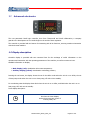
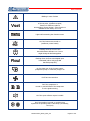
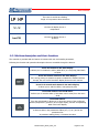
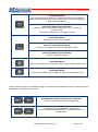
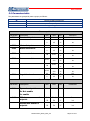
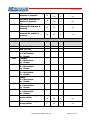
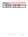
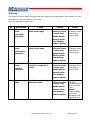
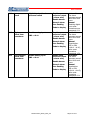
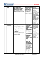
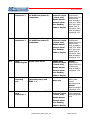
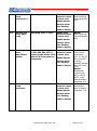
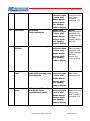
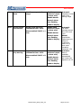
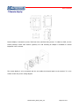
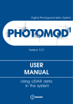
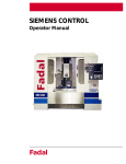
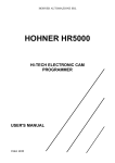
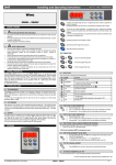
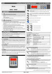
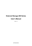
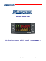
User manual User manual Hydronic groups with scroll compressors MUICHILLUEL_REV00_0812_UK Pagina 1 di 21 User manual INDEX 1.1 Advanced electronics ............................................................................................................. 3 1.2 Display description....................................................................................................................3 1.2.1 Buttons description and their functions............................................................................. 5 2.1 Power On / Off unit.................................................................................................................. 7 3 Alarm display ............................................................................................................................. 8 3.1 Alarm reset .............................................................................................................................. 8 4 Setpoint displaying .................................................................................................................... 9 4.1 Setpoint edit ............................................................................................................................ 9 5 Configuration parameters ....................................................................................................... 10 5.1 User level parameters (Pr1)edit............................................................................................ 10 5.2 Parameters value edit ........................................................................................................... 10 5.4 Parameters table ................................................................................................................... 11 6 Alarms ...................................................................................................................................... 14 7 Remote display ........................................................................................................................ 22 MUICHILLUEL_REV00_0812_UK Pagina 2 di 21 User manual 1.1 Advanced electronics The new parametric Dixell logic controller, born from Thermocold and Dixell collaboration, a company geared to the development of new technologies in the world of heat regulation. The controller is provided with six buttons for interacting with all its functions, ensuring maximum interaction with the thermal machine. 1.2 Display description Controller display is provided with two command lines for the exchange of useful information on the operation and interaction with the operating parameters of the machine, as well as numerous icons. Available information on display: Main display (red): visualization inlet water temperature; Auxiliary display (yellow): visualization condensing pressure; Pressing the set button, the display shows the set of the chiller mode when the unit is on to chiller, the set of heat pump mode when the unit is on to heat pump, off with unit in standby. For condensing units the display shows OnC when the unit is on to chiller, and ONH when the unit is on to heat pump, OFF with unit in standby. Icons display description: On when the lower display shows the current time, hours of working loads, etc.. MUICHILLUEL_REV00_0812_UK Pagina 2 di 21 User manual Blinking in case of alarm On if it is enabled an editing automatic function of the set point, (dynamic set point, function for machines without accumulation, Energy Saving). If the function is enabled but not active, icon is off Lights while accessing the functions menu On if the heaters are turned on (antifreeze, water heater) Flashing when the count of the interval between defrosts is on. Icon is alight during the defrosting phase Flashing when the flow switch digital input is activated (either with pump ON that with pump OFF) On if at least one of the 2 water pumps (evaporator pump or condenser pump) is on On if fans are turned on On if the compressor is turned on, and will flash if the compressor is in the ignition timing On if the open collector output is enable On if the machine is turned on, and this icon represents its operating status: Heat Pump (Snowflake); Cool (sun) MUICHILLUEL_REV00_0812_UK Pagina 3 di 21 User manual The icons LP and HP are flashing if high or low pressure alarm are active °C -°F Lit when the display shows a temperature bar-PSI Lit when the display shows a pressure 1.2.1 Buttons description and their functions The controller is provided with six buttons to interact with user and installer parameters. Following the function and operations description that are accessible through the buttons. Press and release in the main display: It allows you to visualize the chiller (label SETC) or heat pump (label SetH) set point Press and release 2 times in the main display: If the energy saving or dynamic set point is enabled for machines without storage, the icon Vset is lit and the display shows the work real set Press for 3 seconds and release in the main display: It allows you to edit the chiller / heat pump set point Press and release in the ALrM menu: It allows you to reset the alarm (if this alarm can be reset) from the menu ALrM Press and release: from the main display it allows you to show the values of the configured probes (temperature / pressure) in the upper display, and the corresponding label in the lower display. Press and release in the PrG menu: it allows to slide in the parameters folders (ST, CT, etc.) and in the parameters list. In parameter editing phase, it increases the value. MUICHILLUEL_REV00_0812_UK Pagina 4 di 21 User manual Press and release: from the main display it allows you to show the values of the configured probes (temperature / pressure) in the upper display, and the corresponding label in the lower display. Press and release in the PrG menu: it allows to slide in the parameters folders (ST, CT, etc.) and in the parameters list. In parameter editing phase, it increases the value. Press and release: It provides access to menu functions Press for 3 seconds and release: it allows you to adjust the watch in the provided models. Press and release in the PrG menu: it quits the parameter change. Press and release: it allows you to switch on the machine on heat pump or select standby mode Press and release: it allows you to switch on the machine on chiller or select standby mode Some controller functions are available through the multiple keys simultaneous pressure; following are the combinations accepted by the controller. + Simultaneous pressure of buttons for 3 seconds: it allows to access to parameters programming + Simultaneous pressure of buttons: 1. it allows to quit from parameters programming 2. the simultaneous extended pressure of the buttons active the manual defrost MUICHILLUEL_REV00_0812_UK Pagina 5 di 21 User manual 2.1 Power On/Off unit WARNING: Supply power to the unit at least 8 hours before the startup, penalty the annulment of the warranty. Pressing or for about three seconds it can switch on the machine in chiller or heat pump mode. During these 3 seconds, the selected mode led flashes. To change machine mode, for example to pass from chiller to heat pump mode, it must passing to the standby mode before. If the controller is on, the extended pressure on the button of the current mode (chiller or heat pump) forces the machine on standby. In standby mode, you can still to enter in menu to change the parameters. Alarm management is enabled also in standby mode; alarms that occur are equally shown. MUICHILLUEL_REV00_0812_UK Pagina 6 di 21 User manual 3 Alarm display Enter to the function menu: 1. Select “ALrM” function using 2. Press and release ; 3. The pressure on or or ; allows to show active alarms. Press the Menu key or wait the timeout, to exit to this visualization. 3.1 Alarm reset 1. Enter to the function menu; 2. Select the function “ALrM”; 3. Press ; lower display shows the alarm while the upper display shows the label rSt if the alarm is resettable, or NO if it isn’t. Using or you can slide and show all active alarms; 4. Press on the label rSt to reset alarm and pass to the next; 5. Press the Menu key or wait the timeout, to exit to this visualization. MUICHILLUEL_REV00_0812_UK Pagina 7 di 21 User manual 4 Set point display Pressing and releasing the button, it can see the setpoint value, SetC (set chiller) if the machine is on the chiller mode, or SetH (set heat pump) if the machine is on the heat pump mode. Pressing and releasing the button when the machine is on the standby mode, it is possible to display both set points. 4.1 Set point edit 1. Press the key at least for 3 sec; 2. The set point will display blinking; 3. To modify set point value, press 4. Press the and ; key, or wait the timeout to save the new value and to quit from programming; 5 Configuration parameters Controller parameters grouped in functional folders (CF = configuration, CO = compressor,…) with a specific label each. The generic group ALL contain all controller parameters. 5.1 User level parameters (Pr1) edit How to enter in “Pr1”: 1. Press and for some seconds; MUICHILLUEL_REV00_0812_UK Pagina 8 di 21 User manual 2. Icons flash and upper display shows “ALL” (generic parameters group); 3. Slide the parameters groups using and ; 4. Select the group that contains parameters to edit. Pressing the set button, you can enter in the parameters list of that group. Lower display shows parameter label and the upper its value. 5.2 Parameters value edit 1. Enter in the parameters menu; 2. Select parameter; 3. Press the key to eneble the edit; 4. You can edit the value using 5. Press the 6. To exit, press the or ; button to save the new value and to move to the next; key, when you are in parameters viewing (not during the change with blinking value), or wait the timeout. NOTE: The new value is saved also, when you quit because of timeout without pressing the button. WARNING: you can change the CF (configuration parameters) group parameters values, when the machine is on standby mode or on remote OFF, only. You cannot change dF parameters if the unit is on defrost mode. MUICHILLUEL_REV00_0812_UK Pagina 9 di 21 User manual 5.4 Parameters table The parameters are grouped by macro-groups, as follows: ST CF SD ES Thermoregulation parameters Configuration parameters Dynamic set point parameters Energy Saving parameters Thermoregulation Parameter ST01 ST02 Description Summer Set point min max mu Risolution ST05 ST06 °C/°F dec/int 0.0 25.0 °C Dec 0 45 °F int ST07 ST08 °C/°F dec/int 0.0 25.0 °C Dec 0 45 °F int -50.0 -58 ST01 °C Dec °F int 110 °C Dec 230 °F int °C Dec °F int 110 °C Dec 230 °F int 0.0 25.0 °C Dec 0 45 °F int min max mu Risolution 0 1 Offset max summer d. setpoint -30.0 30.0 °C Dec -54 54 °F int Offsett max winter d. setpoint -30.0 30.0 °C Dec -54 54 °F int Summer differential ST03 Winter Set point ST04 Winter differential ST05 ST06 ST07 ST08 ST09 Summer min Set Summer max Set ST01 Winter min Set -50.0 -58 Winter max Set ST03 Regulation band ST03 Dynamic set point Parameter Sd01 Description Dynamic set point 0= Not enable 1= enable Sd02 Sd03 MUICHILLUEL_REV00_0812_UK Pagina 10 di 21 User manual Sd04 Sd05 Sd06 Sd07 Set temp. External Air summer d. setpoint -50.0 -58 110 °C Dec 230 °F int Set temp. External Air winter d. setpoint -50.0 -58 110 °C Dec 230 °F int Differential temp. External Air summer d. setpoint -30.0 30.0 °C Dec -54 54 °F int Differential temp. External Air winter d. setpoint -30.0 30.0 °C Dec -54 54 °F int min max mu Risolution Energy Saving Parameter Description ES01 Begin (0÷24) 0 23.50 Min 10 min ES02 End (0÷24) 0 23.50 Min 10 min ES03 Monday 0 = Not enable 1= Enable Tuesday 0 = Not enable 1= Enable Wednesday 0 = Not enable 1= Enable Thursday 0 = Not enable 1= Enable Friday 0 = Not enable 1= Enable Saturday 0 = Not enable 1= Enable Sunday 0 = Not enable 1= Enable Increase set energy saving chiller 0 1 0 1 0 1 0 1 0 1 0 1 0 1 -30.0 30.0 °C Dec -54 54 °F int 0.1 25.0 °C Dec 0 45 °F int ES04 ES05 ES06 ES07 ES08 ES09 ES10 ES11 Differential energy saving chiller MUICHILLUEL_REV00_0812_UK Pagina 11 di 21 User manual ES12 ES13 Increase set energy saving heat pump -30.0 30.0 °C Dec -54 54 °F int Differential energy saving heat pump 0.1 25.0 °C Dec 0 45 °F int MUICHILLUEL_REV00_0812_UK Pagina 12 di 21 User manual 6 Alarms The controller is able to identify all alarms that may damage the normal operation of the machine. For each alarm code, the controller performs a given action. Below is a table with the alarm codes. Cod P1 Description probe PB1 alarm Cause faulty probe or resistive value out of range Inlet water evaporator Action Enable open collector output / alarm relay Enable buzzer Reset Automatic If resistive value come back in correct range. Generic alarm icon flashing Code to display P2 probe PB2 alarm faulty probe or resistive value out of range Outlet water evaporator Enable open collector output / alarm relay Enable buzzer Automatic If resistive value come back in correct range. Generic alarm icon flashing Code to display P3 probe PB3 alarm Pressure transducer faulty probe or resistive value/or current out of range Enable open collector output / alarm relay Enable buzzer Automatic If resistive value come back in correct range. Generic alarm icon flashing Code to display A01 High pressure alarm Digital input active high pressure switch Enable open collector output / alarm relay Enable buzzer Generic alarm icon flashing Code to display MUICHILLUEL_REV00_0812_UK Automatic The alarm becomes manual after AL10 work hours Manual Disabling digital input reset procedure more paragraph 15.4 Pagina 13 di 21 User manual A02 Low pressure alarm Digital input active low pressure switch Enable open collector output / alarm relay Enable buzzer Generic alarm icon flashing Code to display A05 High pressure alarm from transducer Enable analog input PB3 > AL11 Enable open collector output / alarm relay Enable buzzer Generic alarm icon flashing Code to display A06 Low pressure alarm from transducer Enable analog input PB3 < AL14 Enable open collector output / alarm relay Enable buzzer Generic alarm icon flashing Code to display MUICHILLUEL_REV00_0812_UK Automatic The alarm becomes manual after AL02 work hours Manual Disabling digital input reset procedure more paragraph 15.4 Automatic The alarm becomes manual after AL10 work hours Manual Deactivation: PB3 or PB4 <(AL11 - AL12), more reset procedure paragraph 15.4 Automatic The alarm becomes manual after AL16 work hours Manual Deactivation: PB3 or PB4 >(AL14 + AL15), more reset procedure paragraph 15.4 Pagina 14 di 21 User manual A07 Antifreeze alarm Activation analog input anti-freeze probe Pbr <AR03 for at least AR05 in chiller mode Pbr <Ar27 for at least AR05 in heat pump mode Enable open collector output / alarm relay Enable buzzer Generic alarm icon flashing Code to display A08 Flow alarm evaporator If CO110: activated by digital input active for AL06, the alarm is bypassed for AL04 from power pump evaporator. If CO11=0: activated by digital input active for AL06. If CO110 Enable open collector output / alarm relay Enable buzzer Flow alarm icon flashing Automatic The alarm becomes manual after Ar06 work hours Manual Deactivation: anti-freeze probe Pbr> (AR03 + AR04) in chiller mode more reset procedure paragraph 15.4; antifreeze probe Pbr> (AR27 + AR28) in heat pump mode more reset procedure paragraph 15.4 Automatic Alarm becomes manual if digital input is actived for AL05 Deactivation: Digital input not actives for AL07 Manual Code to display Deactivation: Digital input not actives for AL07, If CO11=0 more reset Enable open procedure collector output / alarm paragraph 15.4 relay Enable buzzer Alarm icon flashing flow Code to display In stand-by or remote OFF, there is the only indication of correct operation of the switch (icon "Flow" active) MUICHILLUEL_REV00_0812_UK Pagina 15 di 21 User manual A09 Alarm compressor 1 Digital input active; bypass Enable open for AL08 from power on collector output compressor / alarm relay Enable buzzer Generic alarm icon flashing Code to display A10 Alarm compressor 2 Digital input active; bypass Enable open for AL08 from power on collector output compressor / alarm relay Enable buzzer Generic alarm icon flashing Code to display A11 Alarm condensing fan Digital input active Enable open collector output / alarm relay Enable buzzer Generic alarm icon flashing Manual Deactivation: Digital input not actives more reset procedure point 15.4. After AL09 work hour, digital input is not active, more reset procedure paragraph 15.4 Manual Deactivation: Digital input not actives more reset procedure point 15.4. After AL09 work hour, digital input is not active, more reset procedure paragraph 15.4 Manual Deactivation: Digital input not actives more reset procedure paragraph 15.4. Code to display A12 A13 Alarm defrosting error End defrost dF07 (maximum time) with DF02 = 2 Code to display Maintenance alarm compressor 1 Operating hours > CO14 Enable open collector output / alarm relay Alert only Enable buzzer Automatic With a later correct defrosting cycle Manual Reset procedure paragraph 15.4. Manual Reset operating hours paragraph 16.6. Generic alarm icon flashing Code to display MUICHILLUEL_REV00_0812_UK Pagina 16 di 21 User manual A14 Maintenance alarm compressor 2 Operating hours > CO15 Enable open collector output / alarm relay Enable buzzer Manual Reset operating hours paragraph 16.6. Generic alarm icon flashing Code to display A15 Maintenance alarm water pump Operating hours > CO16 Enable open collector output / alarm relay Enable buzzer Manual Reset operating hours paragraph 16.6. Generic alarm icon flashing Code to display A16 Alarm high inlet water temperature system Activation by analog input * PB3, PB4, PB1, PB2, if control probe alarm> AL24 after AL26 from power on compressor Enable open collector output / alarm relay Enable buzzer Generic alarm icon flashing Code to display A17 Alarm water pump evaporator Digital input active Enable open collector output / alarm relay Enable buzzer Automatic If the control probe alarm <(AL 24 - AL 25) The unit is OFF or std-by becomes manual after AL27 work hours Manual Deactivation: control probe alarm <(AL24 AL25), more reset procedure paragraph 15.4. Manual Deactivation: reset procedure paragraph 15.4. Generic alarm icon flashing Code to display MUICHILLUEL_REV00_0812_UK Pagina 17 di 21 User manual rtC Alarm timer Timer must be regulated Enable open collector output / alarm relay Enable buzzer Generic alarm icon flashing Manual Setting the clock, more reset procedure paragraph 15.4 Code to display rtF Alarm timer Timer fault Timer malfunction Enable open collector output / alarm relay Enable buzzer Generic alarm icon flashing Manual Reset procedure paragraph 15.4. If after resetting the alarm persists, replace the clock Code to display EE Alarm error EEPROM Loss of data in memory Enable open collector output / alarm relay Enable buzzer Generic alarm icon flashing Manual Reset procedure paragraph 15.4. If after resetting the alarm persists, the device is locked Code to display ACF1 Configuration alarm Unit configured as a heat pump with reversing valve not configured Enable open collector output / alarm relay Automatic With correct reprogramming Enable buzzer Generic alarm icon flashing Code to display Ferr Operating alarm CF04= 3 and CF05 = 3, with digital inputs simultaneously active Enable open collector output / alarm relay Enable buzzer Generic alarm icon flashing Manual Digital input not actives more reset procedure paragraph 15.4. Code to display MUICHILLUEL_REV00_0812_UK Pagina 18 di 21 User manual Afr Line frequency alarm Line frequency out of range Enable open collector output / alarm relay Enable buzzer Automatic Frequency comes back in the working range Generic alarm icon flashing Code to display ALOC Generic alarm lock machine Digital input active for continuous time> AL21. Alarm enabled if AL23 = 1 only Enable open collector output / alarm relay Enable buzzer Generic alarm icon flashing Code to display bLOC Generic alarm, only warning Digital input active for continuous time> AL21. Alarm enabled if AL23 = 0 only Enable open collector output / alarm relay Enable buzzer Generic alarm icon flashing Automatic The alarm becomes manual after AL20 work hours Manual Deactivation: Digital input not active for continuous time> AL 22, more reset procedure paragraph 15.4 Automatic Alarm is resettable automatically and it does not depend on AL 20 Code to display MUICHILLUEL_REV00_0812_UK Pagina 19 di 21 User manual 7 Remote display Remote display is mounted on panel, 72x56 mm hole, and fixed using screws. To obtain an IP65, use the frontal protection eraser mod. RGW-V (optional). For wall mounting an adapter is available for vertical keyboards V-KIT as shown. The remote display is to be connected with the unit inside the electrical panel on the terminal "X" to the contact X9 and X10, as the wiring diagram. MUICHILLUEL_REV00_0812_UK Pagina 20 di 21