1
www.cleveracoustics.co.uk
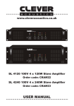
SL 120 100V 120W Slave Amplifier
Order code: CRAM11
SL 240 100V 240W Slave Amplifier
Order code: CRAM12
SL 350 100V 350W Slave Amplifier
Order code: CRAM13
USER MANUAL
WARNING
FOR YOUR OWN SAFETY, PLEASE READ THIS USER MANUAL CAREFULLY
BEFORE YOUR INITIAL START-UP!
CAUTION!
Keep this equipment away from rain,
moisture and liquids.
SAFETY INSTRUCTIONS
Every person involved with the installation, operation & maintenance of this
equipment should:
-
Be competent
-
Follow the instructions of this manual
CAUTION! TAKE CARE USING THIS EQUIPMENT!
HIGH VOLTAGE-RISK OF ELECTRIC SHOCK!!
Before your initial start-up, please make sure that there is no damage caused during
transportation. Should there be any, consult your dealer and do not use the equipment.
To maintain the equipment in good working condition and to ensure safe operation, it is
necessary for the user to follow the safety instructions and warning notes written in this
manual.
Please note that damages caused by user modifications to this equipment are not
subject to warranty.
1
IMPORTANT:
The manufacturer will not accept liability for any resulting damages caused
by the non-observance of this manual or any unauthorised modification to the
equipment.
• Never let the power-cable come into contact with other cables. Handle the
power-cable and all mains voltage connections with particular caution!
• Never remove warning or informative labels from the equipment.
• Do not open the equipment and do not modify the equipment.
• Do not switch the equipment on and off in short intervals, as this will reduce the
system’s life.
• Only use the equipment indoors.
• Do not expose to flammable sources, liquids or gases.
• Do not carry the unit with only one handle. Always carry using both handles.
• Always disconnect the power from the mains when equipment is not in use or before cleaning! Only handle the power-cable by the plug. Never pull out the plug
by pulling the power-cable.
• Make sure that the available voltage is between 220V-240V.
• Make sure that the power-cable is never crimped or damaged. Check the
equipment and the power-cable periodically.
• If the equipment is dropped or damaged, disconnect the mains power supply
immediately.
Have a qualified engineer inspect the equipment before operating again.
• If the equipment has been exposed to drastic temperature fluctuation (e.g. after
transportation), do not switch it on immediately. The arising condensation might damage the equipment. Leave the equipment switched off until it has reached room temperature.
• If your product fails to function correctly, discontinue use immediately. Pack the unit securely (preferably in the original packing material), and return it to your Prolight dealer for service.
• Only use fuses of same type and rating.
• Repairs, servicing and power connection must only be carried out by a qualified
technician. THIS UNIT CONTAINS NO USER SERVICEABLE PARTS.
• WARRANTY; One year from date of purchase.
• If this equipment is operated in any other way, than those described in this
manual, the product may suffer damage and the warranty becomes void.
• Incorrect operation may lead to danger e.g.: short-circuit, burns, electric shocks.
• Do not endanger your own safety and the safety of others!
Incorrect installation or use can cause serious damage to people and property.
2
This 100V line slave amplifier was designed specifically for use in permanent audio
installations, where reliability and premium sound quality are a must. Highly rugged
construction and high efficiency design make this amplifier perfect for continuous duty
applications in situations were power will be left on for indefinite periods of time.
This 100V line amplifier is warranted from defects for one year from the date of purchase.
Should your amplifier require service, either within or beyond that warranty period, please
contact your Prolight Dealer.
This unit includes a host of features, along with an impressive list of specifications, which
are detailed over the next pages. Please take the time to read this document completely
prior to installation of this product.
Slave amplifier series are designed to suit all PA system application in schools, offices and
stor
Features
• 70V, 100V and 4-16Ω loudspeaker outputs
• Balanced XLR line input
• Unbalanced 6.35mm jack line input
• Balanced XLR line output
• Unbalanced 6.35mm jack line output
• Temperature, clip and short circuit protection
• Power, signal, clip, protection and temperature LEDs
• GND/lift switch to prevent ground loop hum
• Fan cooled
• 24V DC and 240V AC inputs for maximum flexibility
3
Specifications
SL 120
SL 240
SL 350
Power output:
120Wrms / 135W
peak
240Wrms / 255Wpeak
350Wrms / 375Wpeak
Speaker outputs:
70V, 100V & 4-16Ω
70V, 100V & 4-16Ω
70V, 100V & 4-16Ω
Sensitivity:
775mV (0dB)
775mV (0dB)
775mV (0dB)
S/N ratio:
>105dB
>105dB
>105dB
Frequency response:
50Hz-18kHz
50Hz-18kHz
50Hz-18kHz
THD:
<1% @ 1kHz, 1/3
rated power
<1% @ 1kHz, 1/3
rated power
<1% @ 1kHz, 1/3
rated power
Controls:
Power, volume, GND,
LIFT
Power, volume, GND,
LIFT
Power, volume, GND,
LIFT
Indications:
Power, signal, clip,
temp and protect
Power, signal, clip,
temp and protect
Power, signal, clip,
temp and protect
Protection:
AC fuse, short circuit,
clipping and high
temperature
AC fuse, short circuit,
clipping and high
temperature
AC fuse, short circuit,
clipping and high
temperature
Power consumption:
200W
400W
500W
DC power supply:
24V DC
24V DC
24V DC
AC power supply:
240V-60Hz
240V-60Hz
240V-60Hz
Dimensions (H x W
x D):
88 x 484 x 353mm
88 x 484 x 353mm
132 x 484 x 408mm
Weight:
9.3kg
13.2kg
14.5kg
Order code:
CRAM11
CRAM12
CRAM13
4
SL120, SL 240
SL 350
SL120, SL 240
SL 350
5
Identification:
1. Power LED - This LED will light up once the amp is switched on
2. SIGNAL LED - This LED will light up when signal is being received
3. CLIP LED - This LED will flash when the output signal starts to distort. A this point turn the
master volume anti-clockwise to prevent damage.
4. PROT LED - This LED will illuminate when the unit goes into protect mode. Switch off the
amplifier and check the output connections for faults or short circuits before powering on and
resuming operation.
5. TEMP LED - Temperature LED will illuminate when overheating. Switch off the amplifier
and leave to cool down.
6. FAN Vent - Don not obstruct, keep clear of dust
7. On/off power switch - Use the switch to power the unit on or off
8. Master volume control - Use this control to increase or decrease the master volume
9. Carry handles
10. GND/LIFT switch - Switch to “GND” position when one unit is used, switch lift “LIFT” when
several units are used to avoid noise caused by several earth
line grounded.
11. DC LED - This LED will light up when optional DC power supply is used
12. FAN Vent - Do not cover to avoid overheating
13. Speaker outputs - Use these to connect the speakers
14. XLR input - Use this to connect signal input from mixer amplifiers
15. 6.35mm mono jack input - Use this to connectsignal input from mixer amplifiers
16. 6.35mm mono jack link - Use this to link out to additional slave amplifiers
17.
XLR
link - Use this to link out to out to additional slave amplifiers
Rack
Installation
18.
DC connections
- Use thisThe
to connect
touse
yourshould
optional
DC power
supply
The24V
SL Series
are rack mountable.
rack you
be 24V
a double
door rack
where you can
open the front and rear panel. When mounting the amplifier into the rack, please make sure that
there is enough space around the amplifier.
Be careful when mounting the amplifier into the rack. Put the heaviest products into the lower
part of the rack. Be aware that fastening the amplifier with four screws on the front panel is not
enough.
Inputs
Short cables runs improve the sound quality remarkably. Input cables should be short and direct,
since high frequencies will mostly be absorbed if the cables are unnecessarily long. Besides that
a longer cable may lead to humming and noise problems. If the cable runs are unavoidable, you
should use balanced cables.
Outputs
The high damping factor of your amplifier supplies a clear sound reproduction. Unnecessarily long
and thin cables used for low impedance (4-16Ω) speakers will influence the damping factor and
thus the low frequencies in a negative way.
Connect your speaker systems via the speaker terminals (COM = -VE)
Examples: 1) COM + 4-16Ω
2) COM + 70V
3) COM + 100V
Note: Please do not use more than one pair of output terminals
6
Connections To The Mains
Before connecting the amplifier to the local mains voltage outlet should be checked to ensure the
available supply is 240V~AC 50Hz. This product is CLASS1 and requires a protective mains earth
to be connected at all times. DO NOT remove or disconnect the earth.
Power On/Off Procedure
After connecting your amplifier to the mains, turn all controls counter clockwise to the “min”
position. Turn on audio sources (MP3 players, CD players, Microphones etc) before powering the
amplifier ON. The last product to be switched on is the amplifier.
If you wish to power off the system, turn the amplifier’s master volume control counter clockwise
to the “min” position before switching the amplifier OFF before any audio sources are switched off.
By following this procedure it will prevent acoustic shocks to the speakers or potential damage to
system components.
Machine operation
1. After connecting all audio source and powering on the power amplifier, adjust the and the
master volume.
2. The Clever Acoustics amplifier features output signal LED with PEAK indication. Should the
PEAK indicator illuminate (flashing) the output of the amplifier is too high, turn the master volume
anti-clockwise to reduce the output.
3. The Clever Acoustics amplifier all features protection with LED indication. Should the
PROTECT indicator illuminate, turn the master volume control anti-clockwise fully and switch off
the amplifier for 15 seconds as the amplifier may have entered PROTECT mode temporarily due
to a peak signal, care should then be taken to ensure all input levels are set correctly. If the
amplifier persists to enter PROTECT mode the amplifier should be switched off and left to cool
for 5-10 minutes before switching back on. If the PROTECT indicator remains lit this indicates a
problem with the amplifier or amplifier load (ie Short Circuit).
4. Speaker & Amplifier systems can produce high sound pressure levels, please operate all
controls with caution to ensure people are not exposed to excessive or dangerous sound pressure
levels.
7
Panel Connections:
SL 120, 240, 350
MAINS
SLAVE AMPLIFIER
24V DC INPUT
(Optional)
MIXER AMPLIFIER
ZONE 1
ZONE 2
100V
COM
COM
100V
ZONE 3
COM
ZONE 4
100V
COM
100V
ZONE 5
COM
COM
100V
OUTPUT
4
8Ω
70V
100V
CHIME
REMOTE MIC
ACTIVE
240V 50Hz
T6.3AL 250V
2 TONE
ON
OFF
PRIORITY
ON
OFF
ON
OFF
ON
XLR BAL
1-GND
2-HOT+
3-COLD-
OFF
+48V PHANTOM
+48V PHANTOM
+48V PHANTOM
+48V PHANTOM
MIC 1
MIC 2
MIC 3
MIC 4
INPUT
LINE 1
LINE 2
4 TONE
CHIME
OUT
TEL
VOLUME
LINE
TEL
INPUT
BATTERY SUPPLY
24V
16A
EMC
GAIN
GAIN
GAIN
GAIN
PRE OUTPUT
8
Speaker connections:
Total impedance
41Ω (SL 120)
20Ω (SL 240)
14Ω (SL 350)
Total impedance
83Ω (SL 120)
42Ω (SL 240)
28.6Ω (SL 350)
Notes:
• Both the 4 - 16Ω, 70V and 100V terminals cannot be used at the same time.
• Impedances indicated in the figures represent the total speaker system (load) impedances.
Loads presented to the amplifier must be equal to or greater than listed above. Speaker
impedances must be measured using a true impedance meter, do not standard multimeters.
WARNING!
Be sure to attache the supplied terminal cover attached after connection. Because high voltage is applied to the speaker terminals,
car should be taken never touch these terminals to avoid
electric shock.
All speaker connections should be made using bare wire or suitable
insulated crimp terminals. Please ensure no loose strands are present
as these may short across terminals causing damage to the amplifier
9
Connection With The Mains
Connect the unit to the mains via the IEC mains
inlet using the 13A UK - IEC cord supplied.
The earth has to be connected.
Switch the unit on. After switching on the speaker system, wait 8 - 10 seconds before you turn the
volume control up in order to avoid speaker damage.
CAUTION! Increase the level of each channel up to the point where the clip LEDs illuminate.
Always check the sound pressure level with a meter in order to keep to the legal threshold.
Balanced XLR Jack Connection
10
Problem Chart
PROBLEM
CAUSE
REMEDY
No Power
The power cord is not connected
Check the power cord and any
No Sound
The power cord of the respective
product is not connected properly or
not at all.
Check the power cord and if the
plugs are properly connected with
the sockets.
The connection socket or the plug
is dirty.
Clean the socket and/or the plug.
Noise
The input signal is too strong
Reduce the input signal via the
gain control.
Distorted Sound
Load impedance is to low
Check load impedance vs amplifier
specification, reduce as required.
extension cables
CAUTION - DANGER TO LIFE
DISCONNECT FROM THE MAINS BEFORE
STARTING MAINTENANCE OPERATION
Cleaning and Maintenance
We recommend a frequent cleaning of the product. Please use a soft lint free and moistened
cloth. Never use alcohol or solvents.
There are no serviceable parts inside the product except for the fuse. Maintenance and service
operations are only to be carried out by authorised dealers.
Replacing the fuse
Only replace the fuse by a fuse of the same type and rating.
Before replacing the fuse, unplug the mains lead.
Should you need any spare parts, please use genuine parts.
Should you have any further questions, please contact your dealer.
11
www.cleveracoustics.co.uk